Week 9 - Parametric study on Gate valve.
Aim : To perform the gate valve simulation for different parametric study .
Introduction : A gate valve is a valve that opens by lifting a barrier (gate) out of the path of the fluid. gate valve is used to control the flow of the liquid & gases also known as a sluice valve.
Gate valves are used in industrial applications like the oil and gas industry, pharmaceuticals, manufacturing, automotive, and marine.
Sloving and modelling Approch:
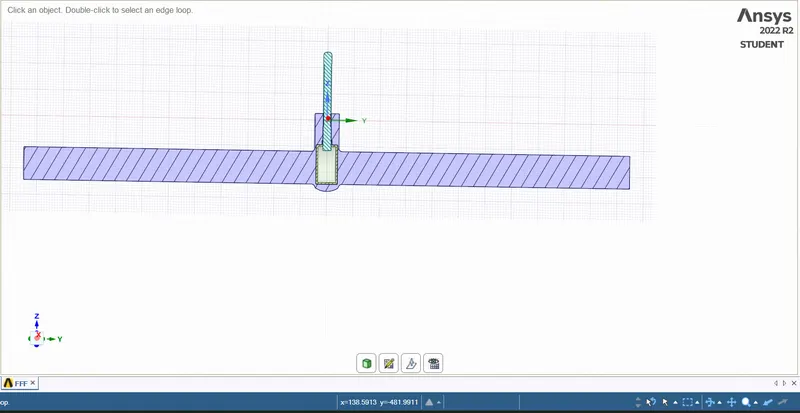
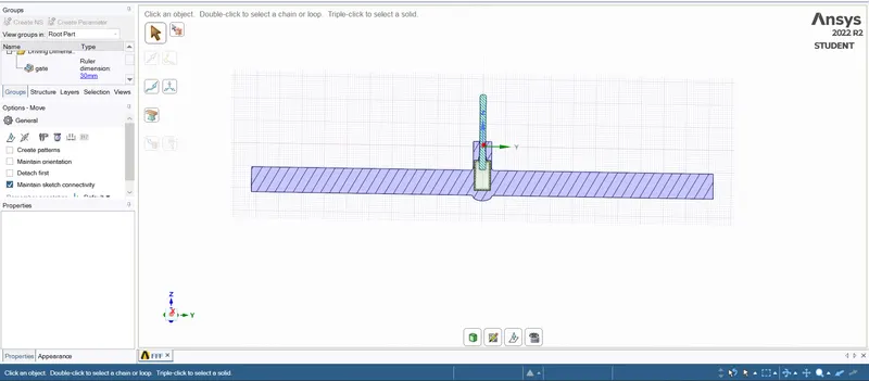
Importing the gemomerty in to the space clam.then paramertic the height for the gate valve.creating the volume from the extacting tool.suppress for physic for the gate valve components, generating the cross section for geometry.taking the extra volume for the analysis.
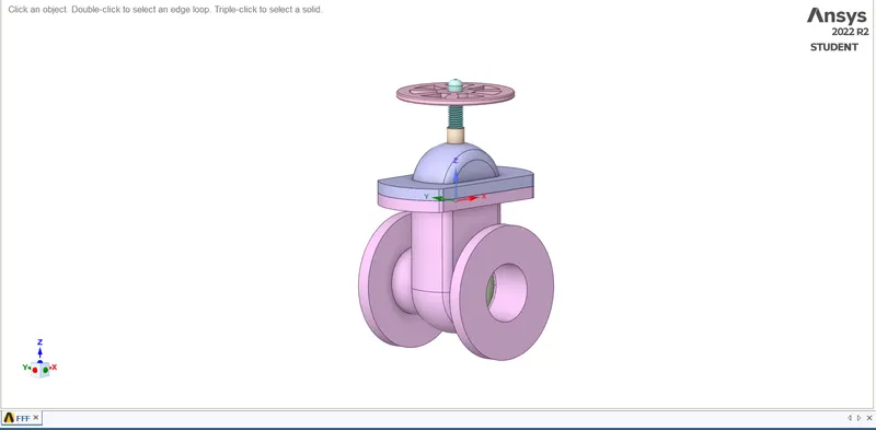
geomerty imported in to space clam.
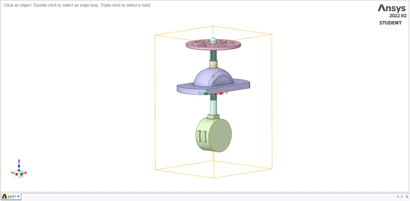
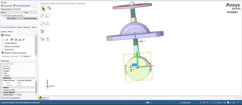
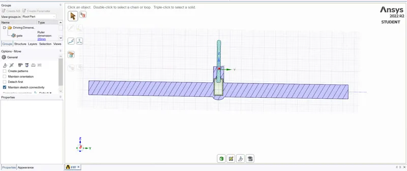
setting the parametric height for gate .
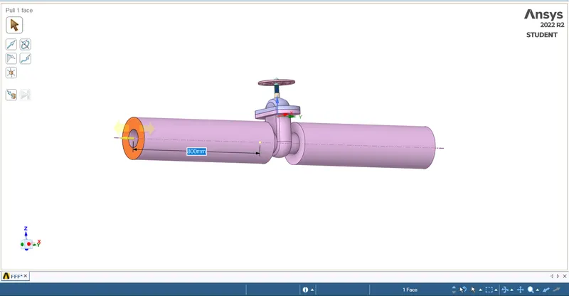
cro
volume extraced for gate valve.
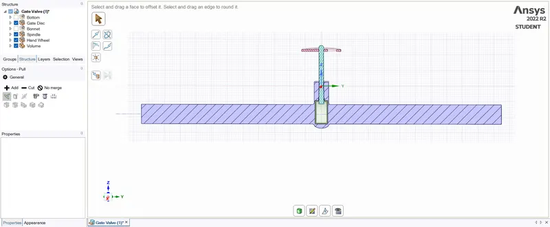
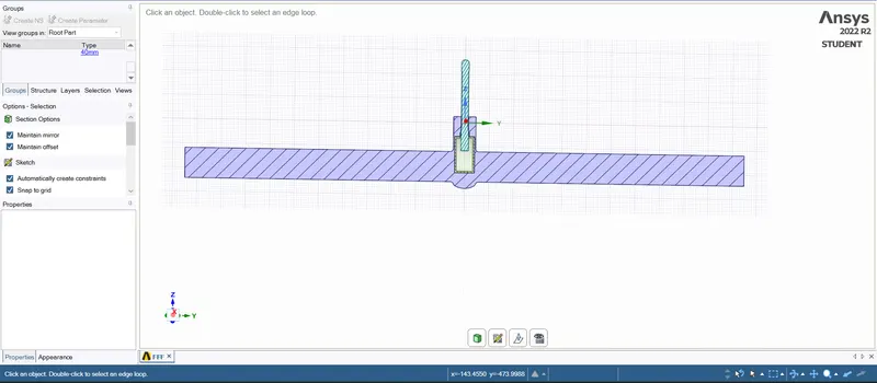
cross section for 10 mm height.
Meshing -
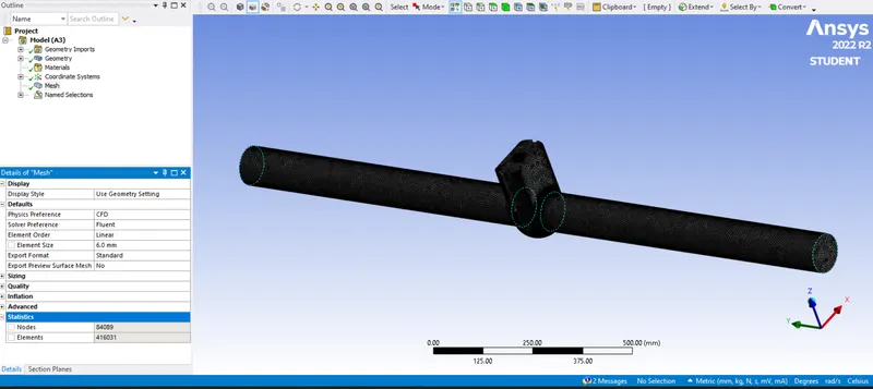
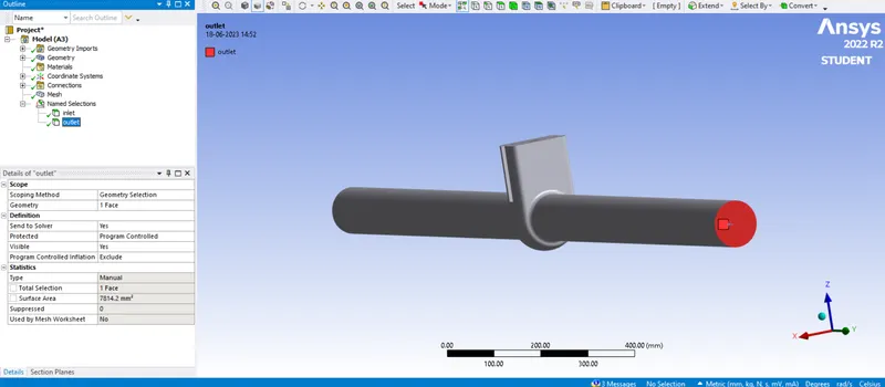
Giving the names for the volume - inlet ,oulet and applying the 5.5mm mesh to the volume geometry.
solver setting:
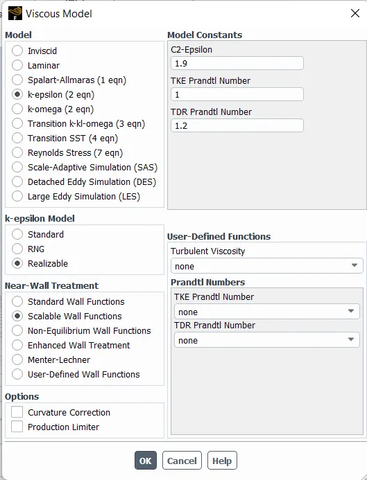
model setting
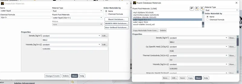
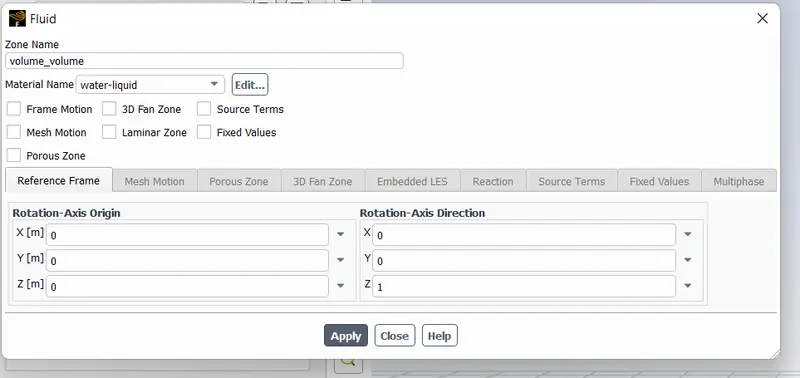
setting up volume fluid as water.
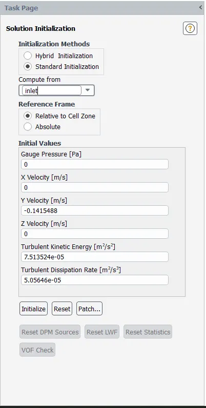
initializing.
setting up the velocity contour , mass flow rate, oulet pressure .
results-
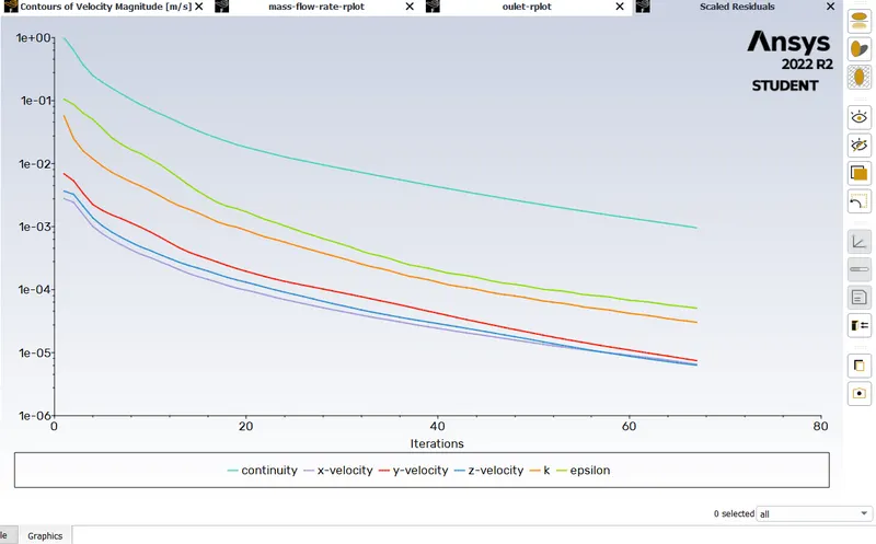
for 10mm lift for gate valve .
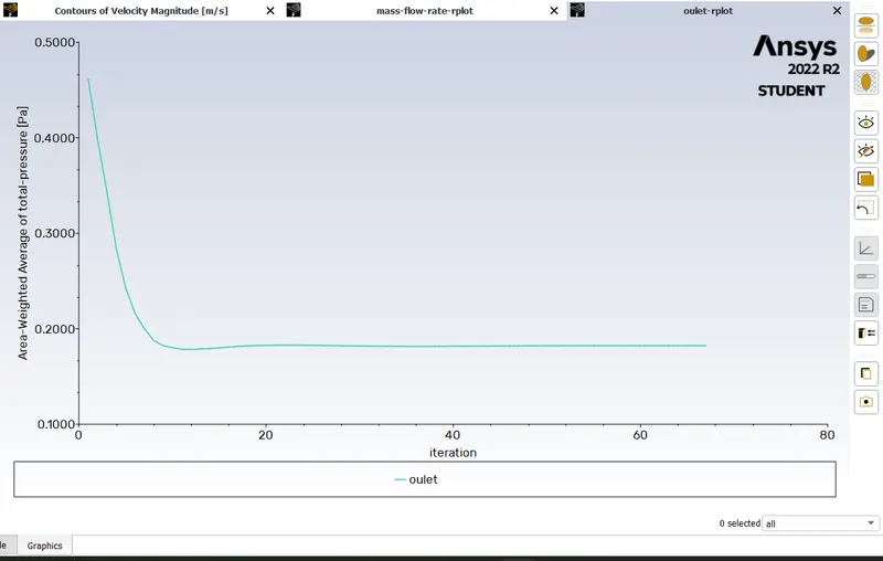
pressure outlet
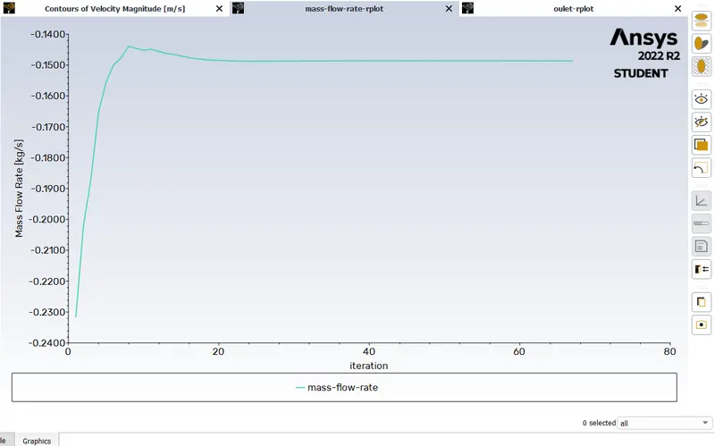
mass flow rate
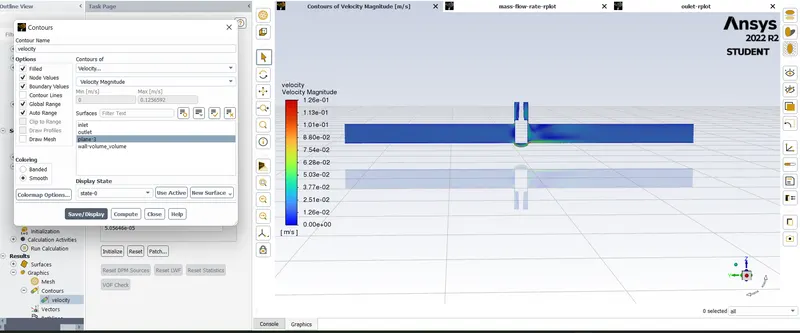
velocity contour
for 20mm lift
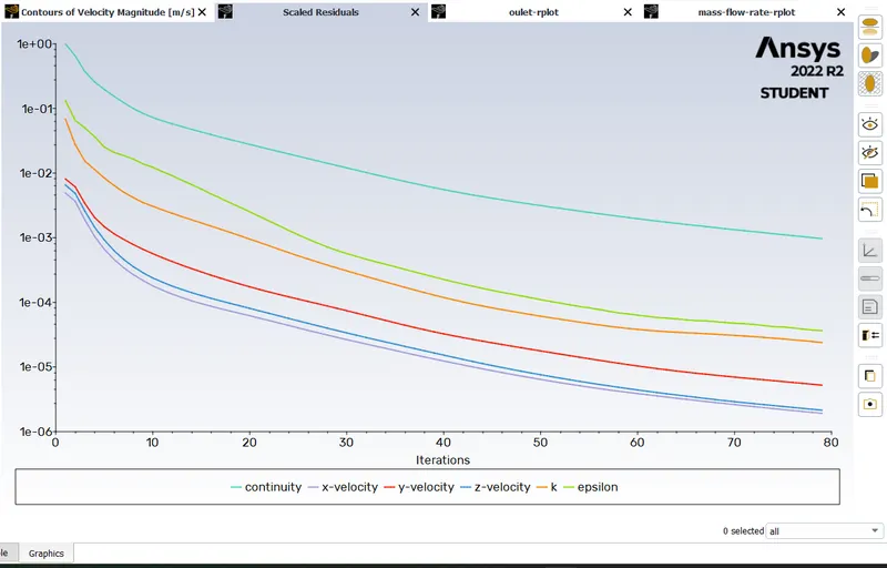
residual
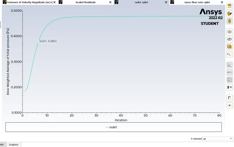
pressure outlet
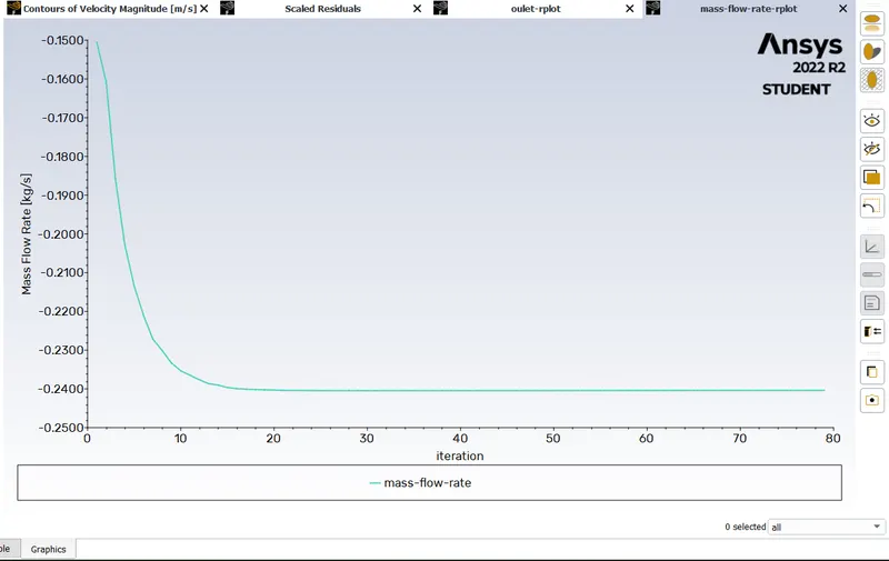
mass flow rate
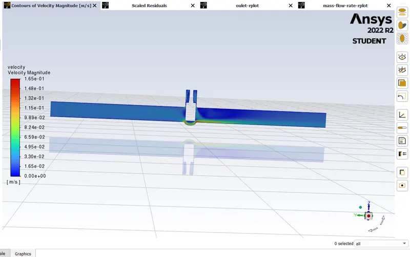
velocity contour
for 30mm lift
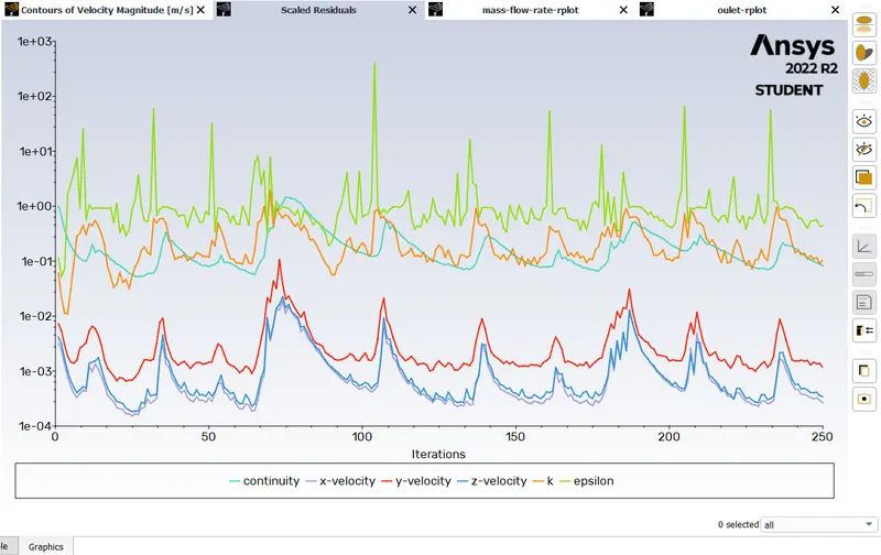
residuals
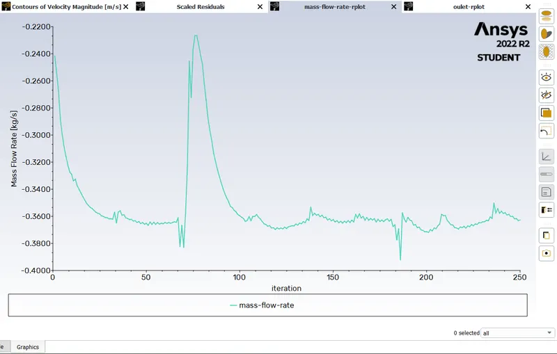
mass flow rate
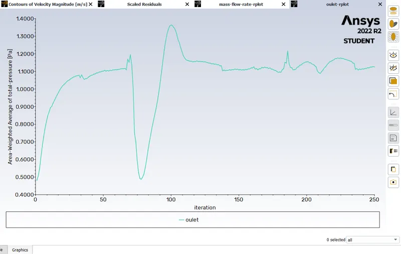
pressure outlet
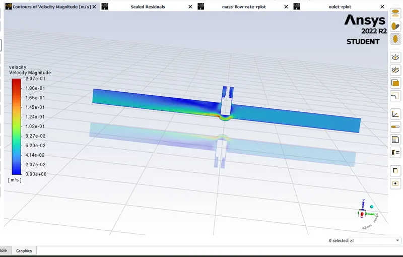
velocity contour
for 40mm lift
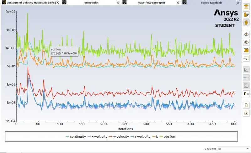
residuals
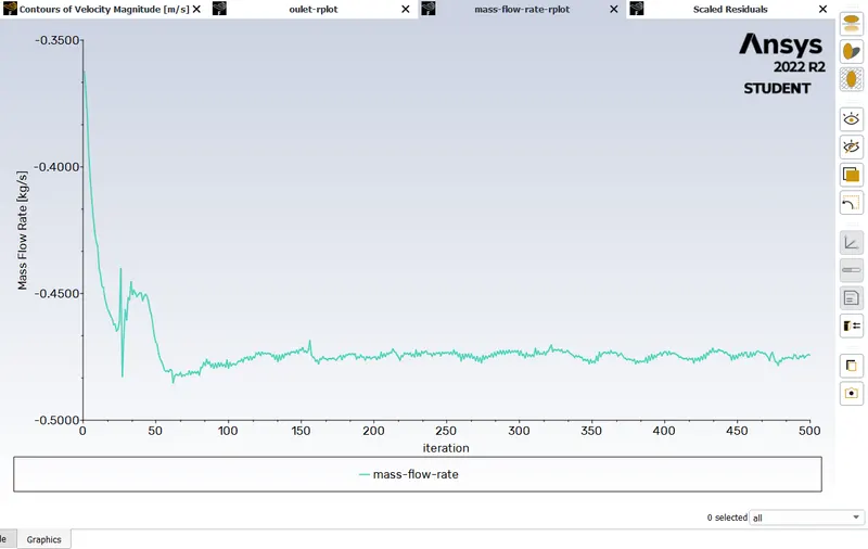
mass flow rate
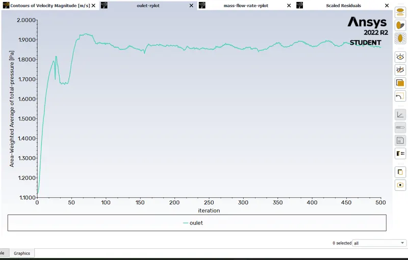
pressure outlet
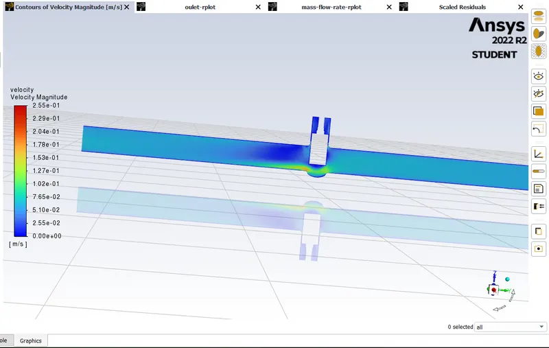
velocity contour
flow coefficient:
The flow coefficient of a device is a relative measure of its efficiency at allowing fliud flow. It describes the relationship between the pressure drop across an orifice valve or other assembly and the corresponding flow rate .
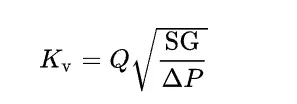
Kv is the flow factor (m3·h−1).
Q is the flowrate ( m3·h−1),
SG is the specific gravity of the fluid (for water = 1),
- ∆P is the differential pressure across the device ( bar).
Kv can be calculated from Cv using the equation:

| S.no | Gate lifted in mm | Specific garvity | Mass flow rate | Pressure inlet | Pressure outlet | Pressure drop | cv | kv |
| 1 | 10 | 1 | -0.1486487 | 10 | 0.18232797 | 9.81767203 | -0.17079 | -0.14773 |
| 2 | 20 | 1 | -0.24043912 | 10 | 0.47827316 | 9.52172684 | -0.28051 | -0.24264 |
| 3 | 30 | 1 | -0.44988941 | 10 | 1.3194449 | 8.6805551 | -0.54971 | -0.4755 |
| 4 | 40 | 1 | -0.47228287 | 10 | 1.845318 | 8.154682 | -0.59539 | -0.51501 |
| 5 | 50 | 1 | -0.57007178 | 10 | 2.7350098 | 7.2649902 | -0.7614 | -0.65861 |
| 6 | 60 | 1 | -0.64349036 | 10 | 3.4993576 | 6.5006424 | -0.90859 | -0.78593 |
| 7 | 70 | 1 | -0.73400069 | 10 | 4.4903798 | 5.5096202 | -1.12574 | -0.97377 |
| 8 | 80 | 1 | -0.81251697 | 10 | 5.5497061 | 4.4502939 | -1.38657 | -1.19938 |
Above table is for different gate lift cv & kv
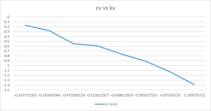
plot cv vs kv
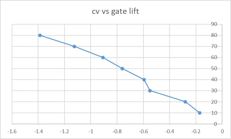
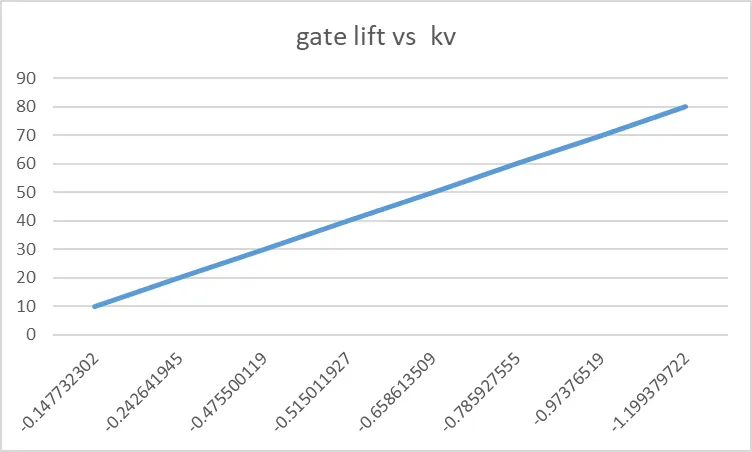
conclusion:
The lower is the gate valve opened for fluid flow, decrease in mass flow rate. lower is the valve opening higher is the pressure difference.
With increase in the valve opening, the mass flow rate also flow coefficient as well as flow factor also increases.