Week 9 - Parametric study on Gate valve.
Aim:
To perform a parametric study on a gate valve at different valve simulation by setting the opening from 10% to 80%
Objectives
- To perform the parametric study on the gate valve by simulating the opening of gate valve ranging from 10mm to 80mm.
- To obtain the mass flow rate for each design point.
- Calculate the flow factor and flow coefficeint for each design point.
Theory:
- Gate valves work by inserting a rectangular gate or wedge into the path of a flowing fluid. They are operated by a threaded stem which connects the actuator (generally a hand wheel or motor) to the stem of the gate. If the valve has a rising stem its position can be seen just by looking at the position of the stem. A gate valve is used to control the fluid flow through lifting and descending the gate. A gate distinct feature is to provide an unobstructed passageway, which includes minimal pressure loss over the valve.
- When the gate is fully opened there is no restriction to the flow hence the pressure drop is low comparatively. Generally, the gate valve are fully closed or fully open as partially opened valve may experience vibration which may lead to excessive wear. A gate valve's main component is body, seat, gate, stem, bonnet, and actuator. the primary mechanism is straight forward where the handwheel is rotated to move the gate up and down via threads. they require more than a 360-degree turn to fully open the valve.
- Gate valves tend to be slightly cheaper than ball valves of the same size and quality. They are slower in actuation than quarter-turn valves and are for applications where valve operation is infrequent, such as isolating valves. Gate valves should be used either fully open or fully closed, not to regulate flow. Automated gate valves exist with either an electric or pneumatic actuator, but a manual gate valve is cost-effective since they have infrequent usage. Gate valves are widely used for all types of applications and are suitable for both above-ground and underground installation. They are suitable for most fluids including steam, water, oil, and gas, etc.
Simulation Methodology:
Modeling
The mode for the gate valve can be prepared in any CAD software and thus can be imported in Ansys Space Claim.
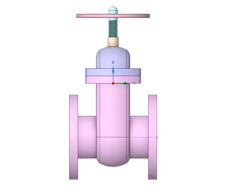
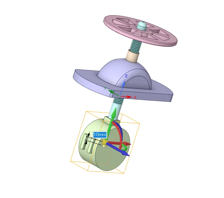
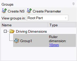
To simulate the effect of the stopper on the mass flow rate of the fluid at the outlet the stopper is moved 10mm in the positive Z-direction so that the flow path is partially open. This is parametrized. Next, the fluid is extracted from the solid geometry. The parameterization helps us change its value and compute the required output parameters without having to repeat the same processes again. Since we are not interested in the analysis of solid geometry, it is suppressed.
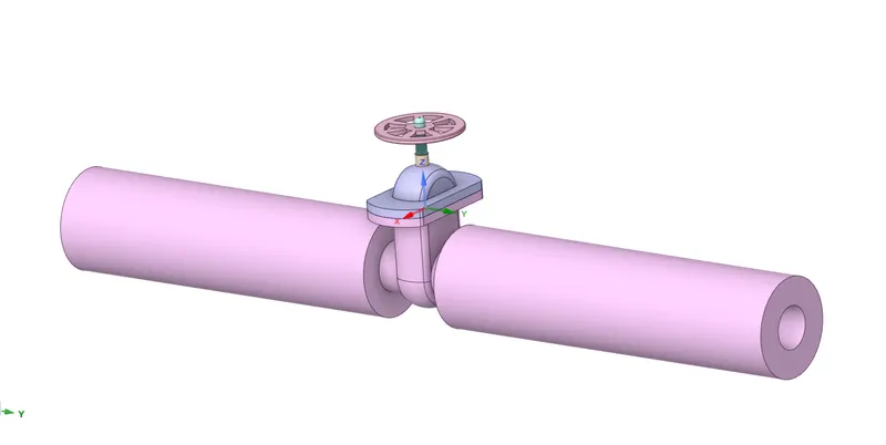
Extracted volume:
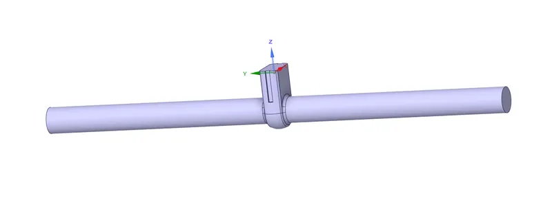
Create parametres for 10mm
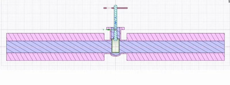
Sectional view:
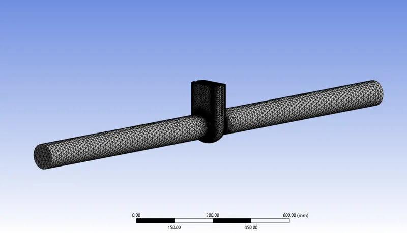
Once the geometry is defined, the meshing is done.
Setting Up Physics:
First of all the mesh is set up and the solver is defined as below:
Solver Type: Pressure Based Solver
Gravity: -9.81 (in negative z direction)
Solver: Steady State
Model: k-epsilon model (realisable with scalable wall function)
Material: Water
Cell Zone: Fluid(water)
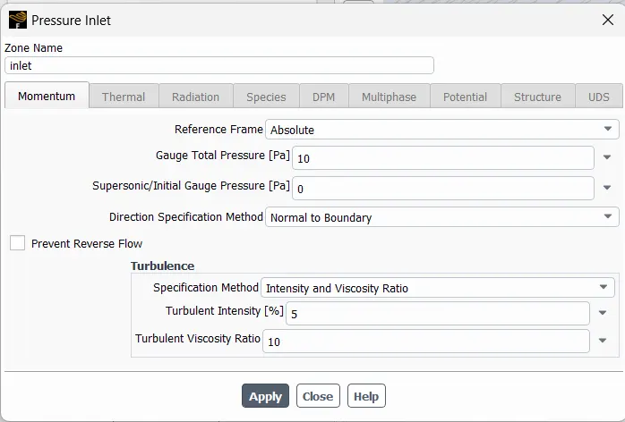
Inlet Boundary Condition : Pressure Inlet (10Pa)
Outlet Boundary Condition: Pressure Outlet
The model will be initialised with standard initialisation and the data will be computed from inlet.
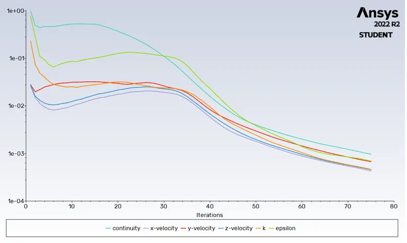
After solving for 250 iterations the results can be seen below:
1. Residuals:
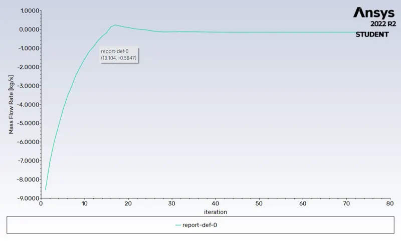
2. Mass Flow rate at Outlet:
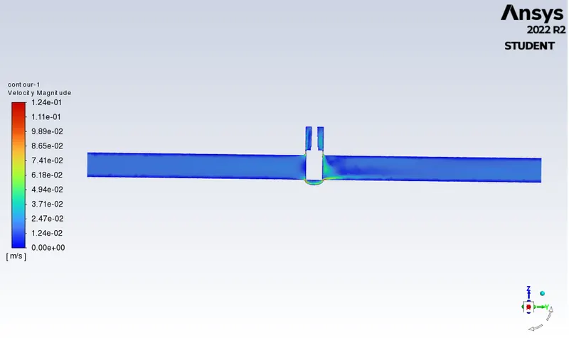
3. Velocity Contour:
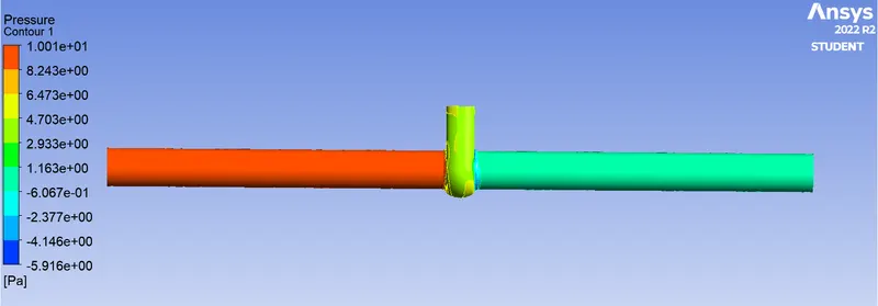
4. Pressure Contour:
5. Streamline:
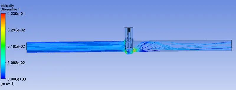
As above we parameterised the gate disc with th edifferent movements we will exit the fluent and will notice that the new option of parameters is activated we will click that and set the new design points upto 80mm gate disc lift height with the increment of 10mm for each consecutive design point and thus we will update all the design points.
CASE 2: 80mm lift
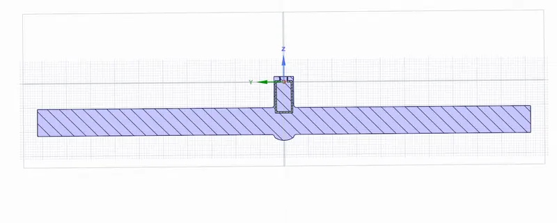
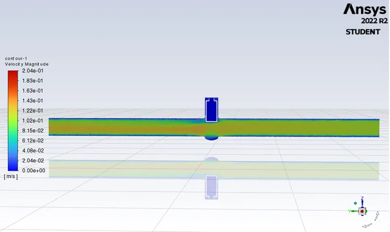
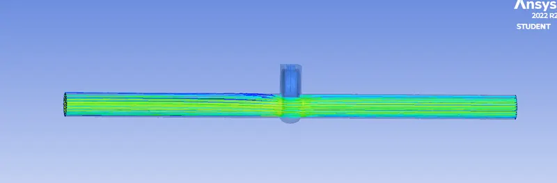
The results for the gate disc with 20mm lift can be seen below:
1. Residuals:
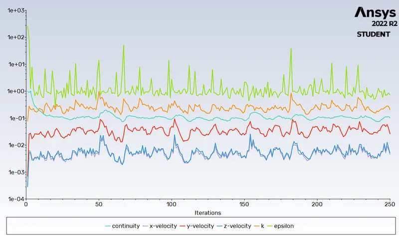
2. Mass Flow rate at Outlet:
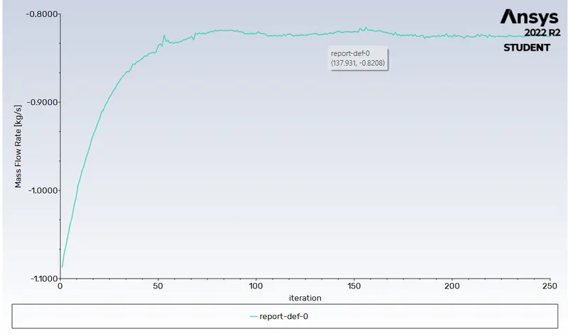
3. Velocity Contour:
4. Streamlime:
As above we parameterised the gate disc with th edifferent movements we will exit the fluent and will notice that the new option of parameters is activated we will click that and set the new design points upto 80mm gate disc lift height with the increment of 10mm for each consecutive design point and thus we will update all the design points.
Next, we move on to the parameters tab to calculate the mass flow rates for the different stopper heights, and the following results were obtained
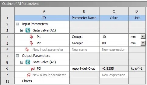
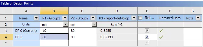
- The negative signs for the mass flow rates imply that the fluid is exiting the domain. The mass flow rate is calculated for the stopper lifts from 10mm to 80mm. The mass flow rate increases with the increase in the lit of the stopper. When the stopper is lifted gradually, the space available for the passage of the fluid increases hence the mass flow increases. When we perform the parametric study, Ansys automatically changes the mesh as per new geometry using the same mesh specifications given earlier, and solves and calculates the output parameters, thereby saving time comparatively if it was done manually.
CONCLUSION:
- The low lift height refers to the higher pressure drop and thus low flow rate through the valve.
- The negative mass flow is due to the mass exiting the outlet.
- With the help of the parameters the solving time and effort can be reduced drastically.
Related terms
Flow Coefficient:
The flow coefficient of a device is a relative measure of its efficiency at allowing fluid flow. It describes the relationship between the pressure drop across an orifice valve or other assembly and the corresponding flow rate. Mathematically the flow coefficient Cv (or flow-capacity rating of the valve) can be expressed as:
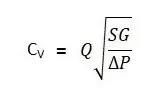
Q is the rate of flow (expressed in US gallons per minute)
SG is the specific gravity of the fluid (SG for water= 1)
ΔP is the pressure drop across the valve (expressed in psi)
In more practical terms, the flow coefficient Cv is the volume (in US gallons) of water at 60 °F that will flow per minute through a valve with a pressure drop of 1 psi across the valve. The use of the flow coefficient offers a standard method of comparing valve capacities and sizing valves for specific applications that are widely accepted by the industry. The general definition of the flow coefficient can be expanded into equations modeling the flow of liquids, gases, and steam using the discharge coefficient.
Flow Factor:
The metric equivalent flow factor (Kv; commonly used in Europe and Asia) is calculated using metric units:
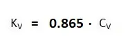
Q is the rate of flow (expressed in m^3/h)
SG is the specific gravity of the fluid (SG for water= 1)
∆P is the pressure drop across the valve (expressed in bar).
The Kv factor of a valve indicates "The water flow in m3/h, at a pressure drop across the valve of 1 kgf /cm2 when the valve is completely open.
Mass flow rate for 10mm and 80mm lift: