Week 9 - Parametric study on Gate valve.
PARAMETRIC STUDY ON GATE VALVE
Gate Valve
A gate valve, also known as a sluice valve, is a valve that opens by lifting a gate out of the path of the fluid. Gate valves require very little space along the pipe axis and hardly restrict the flow of fluid when the gate is fully opened. The gate faces can be parallel but are most commonly wedge-shaped.
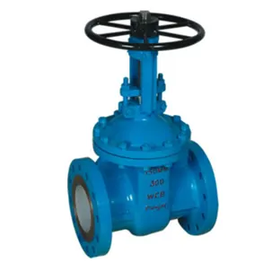
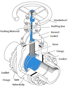
Gate valves are used to shut off the flow of liquids rather than for flow regulation. When fully open, the typical gate valve has no obstruction in the flow path, resulting in very low flow resistance. The size of the open flow path generally varies in a nonlinear manner as the gate is moved. This means that the flow rate does not change evenly with stem travel. Depending on the construction, a partially open gate can vibrate from the fluid flow. Gate valves without an extra sealing ring on the gate or the seat are used in applications where minor leaking of the valve is not an issue, such as heating circuits or sewer pipes. Gate valves are mostly used with larger pipe diameters (from 2" to the largest pipelines) since they are less complex to construct than other types of valves in large sizes.
Parametric Study in Fluent
During CFD simulations involving multiple cases, it becomes difficult to set the case separately for each different case. Hence, Parameter option can be used in Fluent by running the case once and obtaining result of different cases by changing the Design parameter.
This can be utilised by clicking on the P button when using the move option.
Flow Coefficient and Flow Factor
The flow coefficient of a device is a relative measure of its efficiency at allowing fluid flow. It describes the relationship between the pressure drop across an orifice valve or other assembly and the corresponding flow rate.
Mathematically the flow coefficient Cv be expressed as :
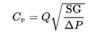
where:
Q is the rate of flow (expressed in US gallons per minute),
SG is the specific gravity of the fluid (for water = 1),
ΔP is the pressure drop across the valve (expressed in psi).
CFD ANALYSIS
Geometry
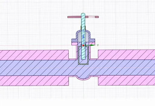
The Gate valve was exported into Spaceclaim.
Using the pull option, the surface is pulled as shown below.
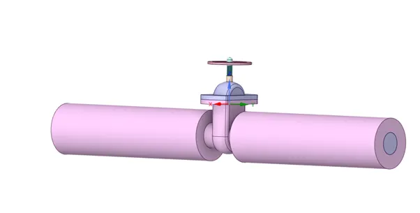
Using the move option, a group parameter was created to conduct the Parameter study.
MESH
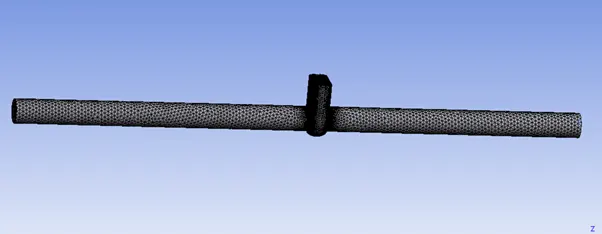
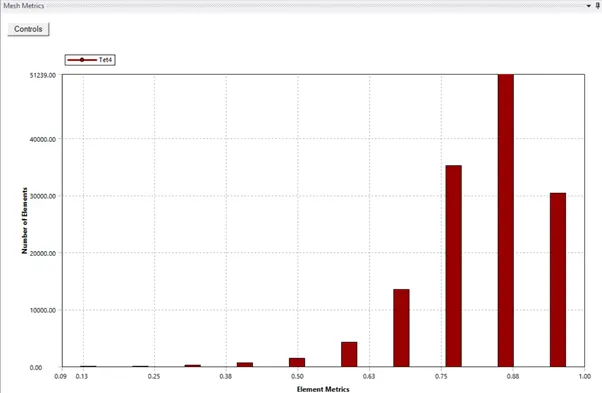
Names were assigned to inlet and outlet.
Setting Up Physics
- Solver-Pressure based-steady solver-gravity enabled Z= -9.81m/s^2
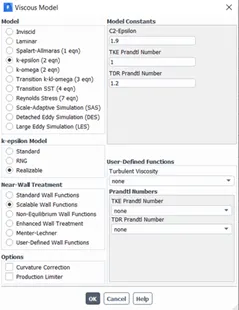
- Model-k epsilon, realisable, scalable wall function
- Boundary condition, inlet- pressure based, inlet pressure = 10pa, outlet pressure = 0pa.
Initialisation
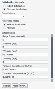
Simulation was made for 7 different cases. (10mm-80mm)
RESULTS
Case 1(10mm opening)
Residuals
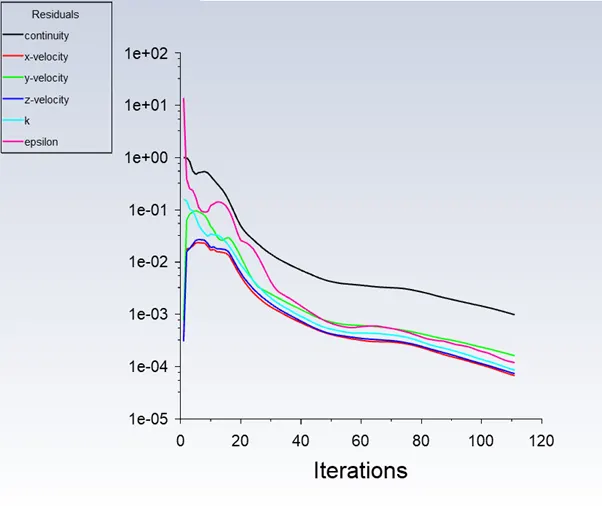
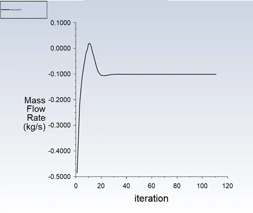
Mass Flow Rate
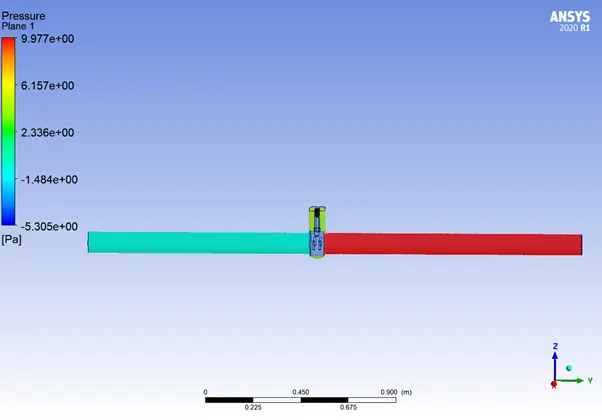
Pressure Contour
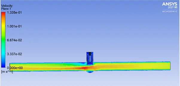
Velocity Contour
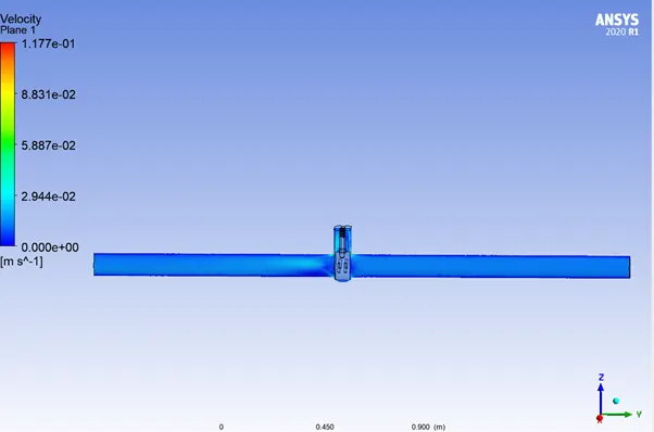
Case 2(20mm opening)
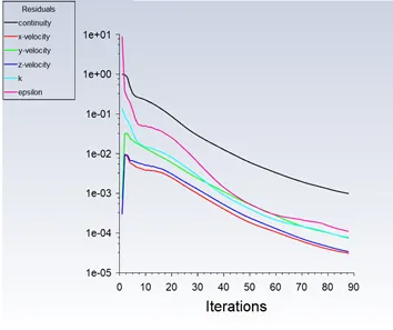
Residuals
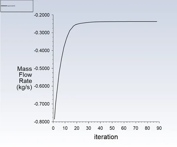
Mass Flow Rate
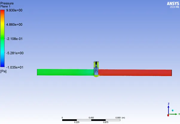
Pressure Contour
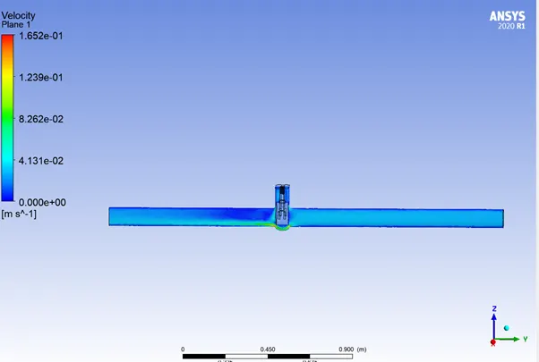
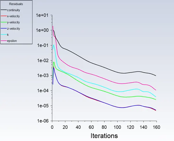
Case3(30mm opening)
Residuals
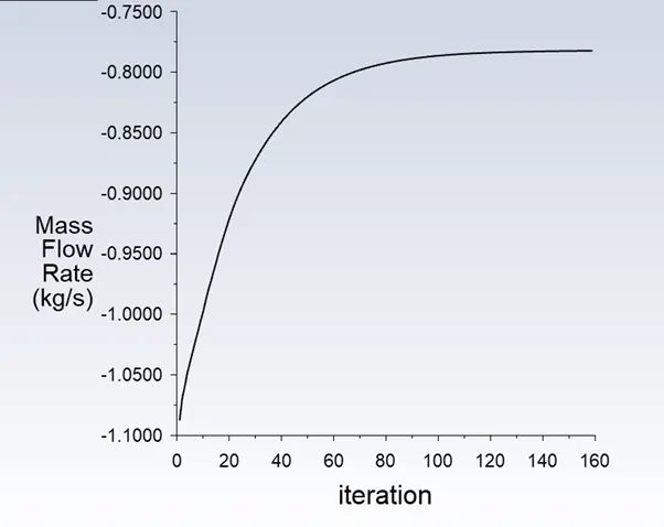
Mass Flow Rate
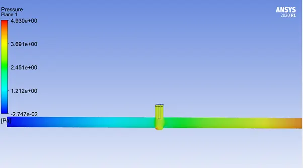
Pressure Contour
Velocity Contour
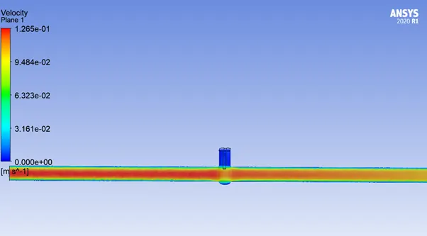
Case 4(40mm opening)
Residuals
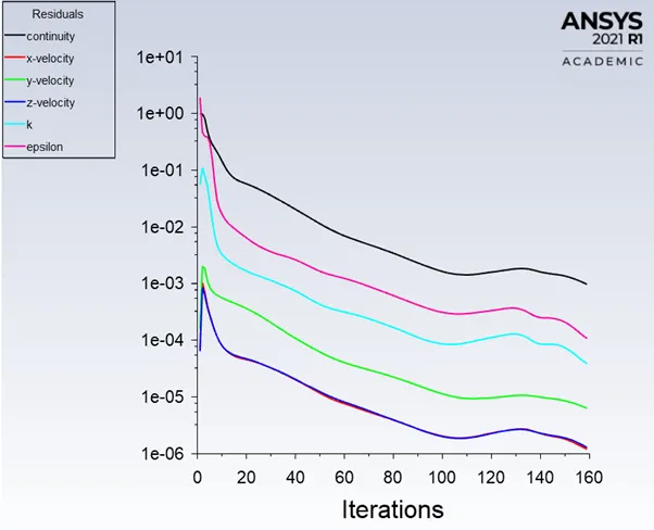
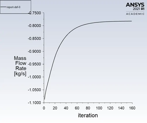
Mass Flow Rate
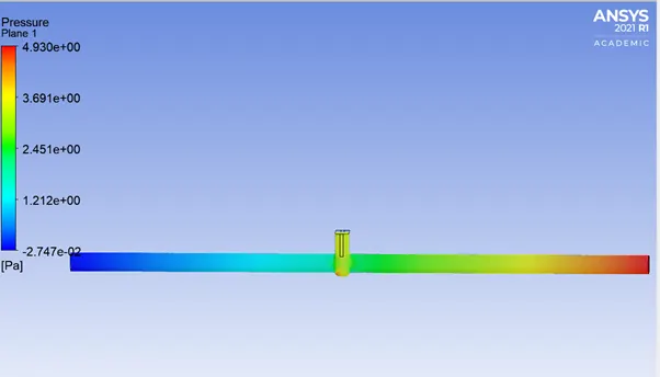
Pressure Contour
 '
'
Velocity Contour
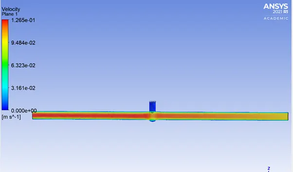
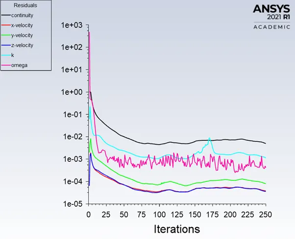
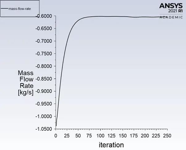
Case 5(60mm opening)
Residuals
Mass Flow Rate
Pressure contour
Velocity Contour
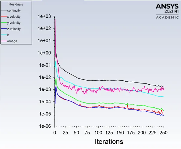
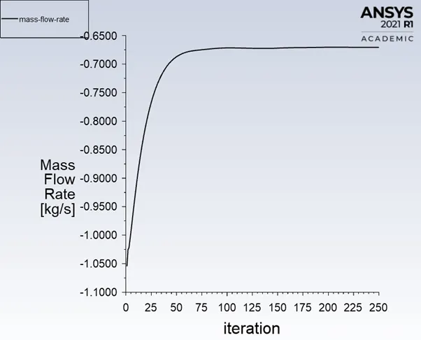
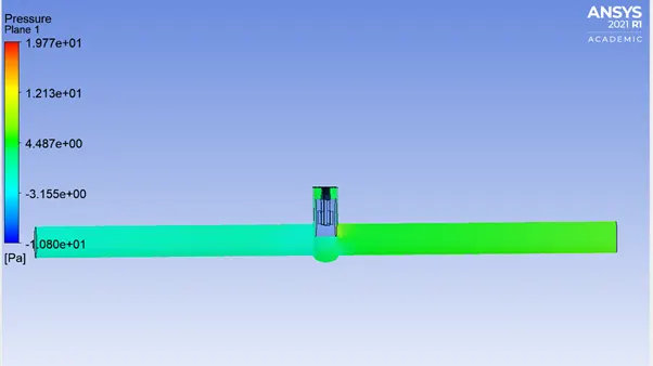
Case6(70 opening)
Residuals
Mass flow rate
Pressure Contour
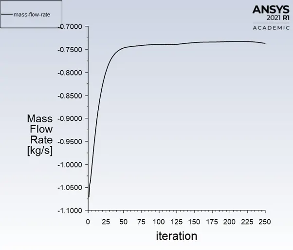
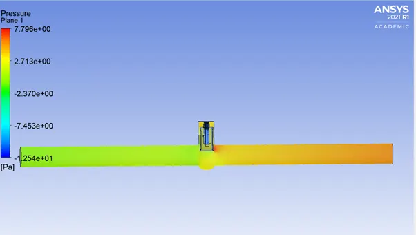
Case 7(80mm opening)
Residuals
Mass Flow Rate
Pressure Contour
Velocity Contour
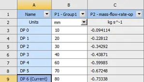
Mass Flow Rate for each case
|
Case |
Lift(mm) |
Mass flow rate (kg/s) |
Mass flow rate (gallon/min) |
Pressure (Pa) |
Pressure (psi) |
Flow Coefficient |
Flow Factor |
|
1 |
10 |
-0.09411 |
-2.01760 |
10 |
0.00145 |
52.9847 |
45.6728 |
|
2 |
20 |
-0.22812 |
-4.89062 |
10 |
0.00145 |
128.4339 |
110.7100 |
|
3 |
30 |
-0.34292 |
-7.35179 |
10 |
0.00145 |
193.0674 |
166.4240 |
|
4 |
40 |
-0.43871 |
-9.40541 |
10 |
0.00145 |
246.9981 |
212.9123 |
|
5 |
60 |
-0.59985 |
-12.86006 |
10 |
0.00145 |
337.7216 |
291.1160 |
|
6 |
70 |
-0.67248 |
-14.41716 |
10 |
0.00145 |
378.6130 |
326.3644 |
|
7 |
80 |
-0.73338 |
-15.72278 |
10 |
0.00145 |
412.9003 |
355.9200 |
CONCLUSION
- Based on the above result, we can conclude mass flow rate and flow coefficient increases with disc opening
- Velocity of flow increases with disc opening.