Week 9 - Parametric study on Gate valve.
AIM -
A steady-state simulation for the parametric study of flow through a gate valve is to be performed in Ansys Fluent.
INTRODUCTION & THEORY -
Gate Valve -
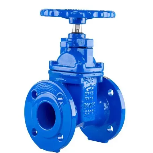
The most common type of valve in water supply systems is a gate valve. It is a linear-motion isolation valve with the ability to stop or allow flow. The closure element of a gate valve slides into the flow stream to provide shutoff and thus acts like a gate. A gate valve, also known as a sluice valve, is a type of valve that opens by lifting a gate out of the fluid's path. Gate valves take up very little space along the pipe axis and barely restrict fluid flow when fully opened.
 |
Parametric Study -
A parametric study is the investigation of the effect of various geometric or physical parameters, or both, on the solution of a problem. You can use metric studies to select parameters for evaluation, define the parameter range, specify design constraints, and analyze the outcomes of each parameter variation. Parametric CFD analysis has been demonstrated to be critical in the engineering design of fluid-dynamic devices. Engineering methods can be costly and time-consuming without them. By the time a project is finished, there may be a more efficient way to use the device.
Flow Coefficient & Flow Factor -
The flow coefficient (Cv) is also known as the valve flow coefficient. It is an imperial measurement system unit that is defined as the flow of water through a valve at 60°F in US gallons per minute (GPM) at a pressure drop of 1 pound/square inch (lb/in²).
`Cv = Q sqrt frac {SG} {Delta P}` ...(1)
Q = Flow in US GPM,
SG = Specific Gravity of water (for water = 1)
ΔP = Differential Pressure (psi)
The flow factor (Kv) is the metric system equivalent of the flow coefficient (Cv). Also known as the International System of Units (abbreviated as SI system). It is defined as the flow of water in cubic meters per hour (m³/hr) at a pressure drop of one bar and temperatures ranging from 5 to 30 degrees Celsius.
`Kv = Q sqrt frac {SG} {Delta P}` ...(2)
Q = Flow in m³/hr,
SG = Specific Gravity of water (for water = 1)
ΔP = Differential Pressure (bar)
The Flow Factor (Kv) must not be confused with the Discharge Coefficient (k). Discharge Coefficient (k) is a non-dimensional characteristic of a valve that is used to calculate the flow that discharges from a tank to the environment.
Relationship between Cv and Kv:
Cv = 1.156 Kv or Kv = 0.864 Cv ...(3)
Physical Significance of Cv & Kv:
• The hydraulic capacity of a control valve is described by the flow coefficient Cv and the flow factor Kv.
• Quickly compare different valve brands and flow capacities.
• Assist in the selection of a valve that is the correct size (and not oversized) for the application.
• It is easy to see how the valve you choose will affect the pressure in your system.
SOLVING & MODELLING APPROACH -
The following workflow is implemented for each CFD simulation;
• Problem finding
• Pre-processing
• Solver or Processing
• Post-processing
In this challenge, we are attempting to determine how our mass flow rate will change for various positions of the gate disc, so the only difference in the case setup will be this geometrical value. We are essentially automating the meshing, solution setup, and post-processing stages by parametrizing the lift value, which saves time and is more efficient. For the parametric study, the input parameter that needs to be parameterized is the lift of the gate disc by opening the gate valve from 10 % to 80 %.
In SpaceClaim, the parameter for lifting the gate valve will be initialized, and the model will be made suitable for further processes. Mesh will be generated over the geometry in the Mesh file, and components will be assigned with proper named selection. Solver settings will be entered in the Setup file based on the conditions specified in the problem statement. The simulation will be run for eight cases, that is, eight gate disc positions. During the post-processing phase, results will be calculated and saved as plots and contours in the Result file. After analyzing the study results, conclusions will be drawn.
PRE-PROCESSING -
Import the gate valve geometry model into SpaceClaim. Pull the flange coupling from both sides using the "Pull" tool with a value of 500 mm to properly view the contours in post-processing. Hide the bonnet and hand wheel before using the "Volume Extract" tool and correctly selecting the three edges to extract the fluid volume. When looking at the model's cut section, there is no visible space between the gate disc and the bottom of the flange coupling as we haven't introduced any gap yet.
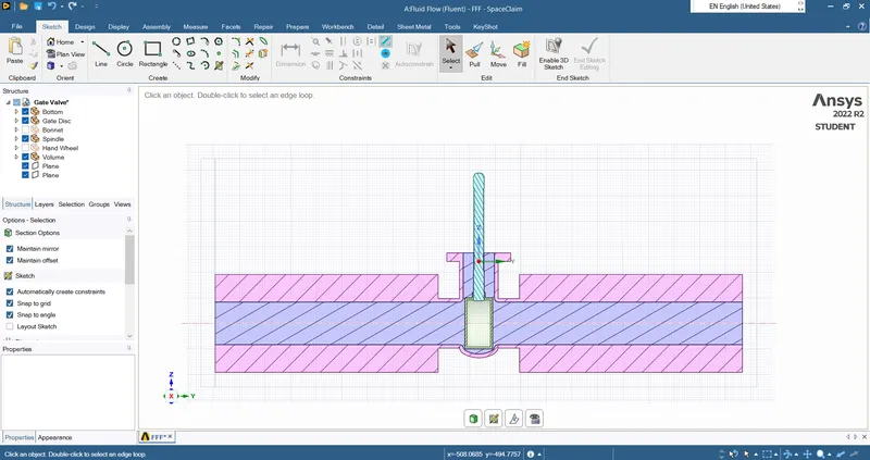 |
Note: Planes must first be created in order to see the cut sectional view.
It is instructed to parameterize the gate valve by opening it between 10 % and 80 %. The disc measures 100 mm in diameter. As a result, we will begin with a 10 mm gap in accordance with this relationship. Up until the gap reaches 80 mm, we will gradually increase it by 10 mm each time.
The gate valve should be parameterized as follows:
• Hide the fluid volume and the bottom.
• Select the disc with the 'Move' tool, switch to component selection, click the upward arrow, drag upward, and set the value to 10 mm.
• Click "Create Parameter" in the Groups section of the outline tree. Click "Update Volume Body in Context" after choosing Volume in the Structure section.
As a result, the input parameter for lifting the gate disc is initialized.
The other components should be hidden and suppressed for physics since they are not relevant to the analysis.
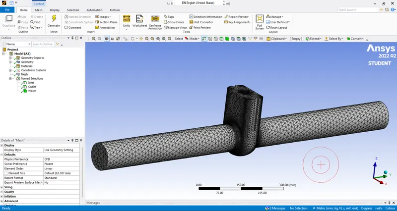
Update the mesh and assign the named selection in the mesh file:
Inlet: face selection
Outlet: face selection
Water: body selection
 |
SOLVER -
In the Setup file, provide the following solver settings:
|
Fluent Setup |
||
|
Sr. No. |
Setup |
Command |
|
1 |
Solver Type |
Pressure based |
|
2 |
Solver Time |
Steady State |
|
3 |
Gravity |
Enabled |
|
4 |
Viscous Model |
K epsilon Realizable |
|
5 |
Material |
Water |
|
6 |
Input Parameter |
Lift of gate valve |
|
7 |
Output Parameter |
Mass Flow Rate at Outlet |
|
8 |
Inlet & Outlet |
Pressure Boundary Condition; Inlet = 10 Pa (Gauge) |
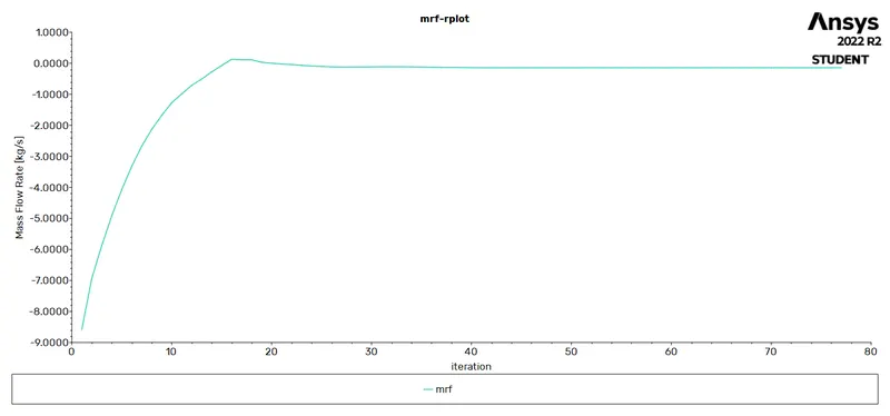
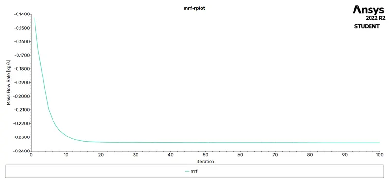
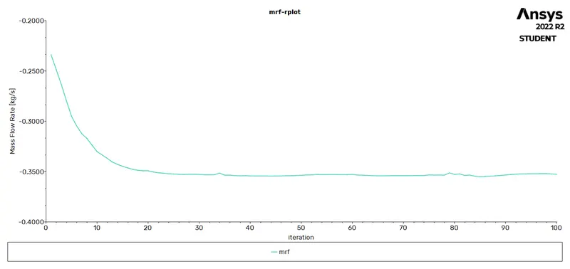
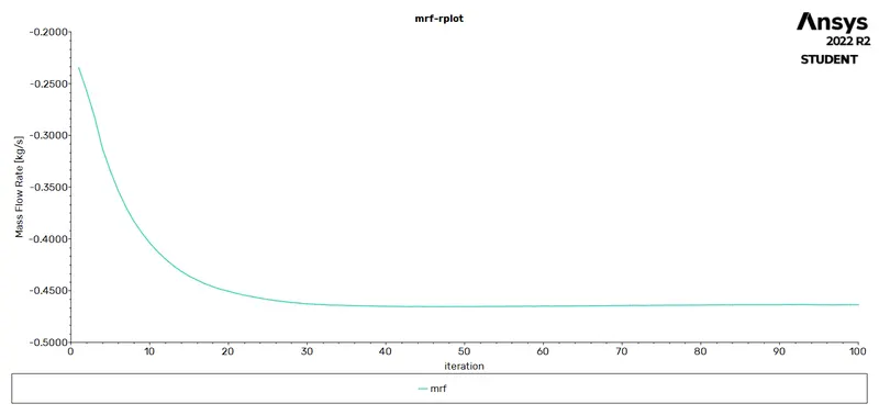
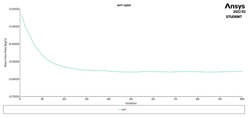
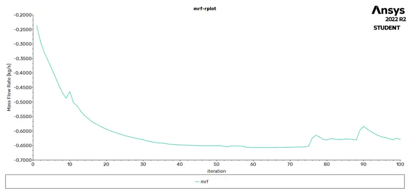
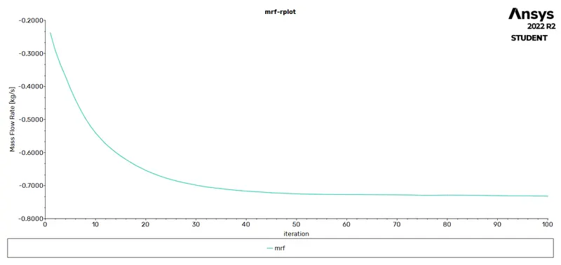
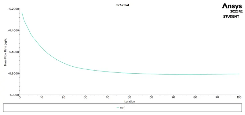
The 'Reports Definition' tool was used to create a report that calculated the Mass Flow Rate at the outlet.
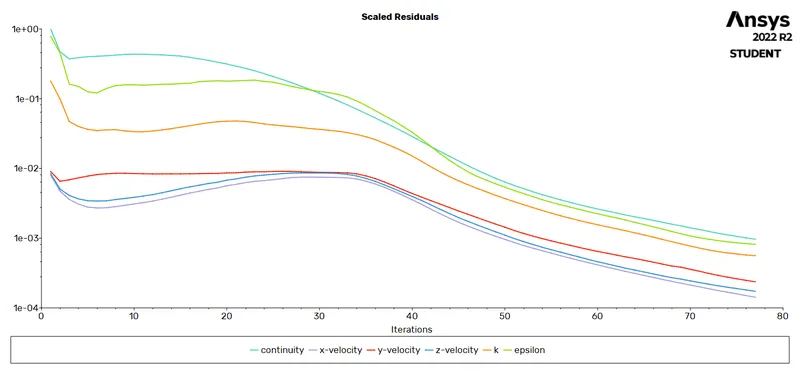
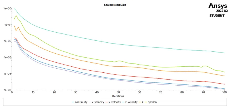
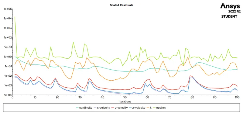
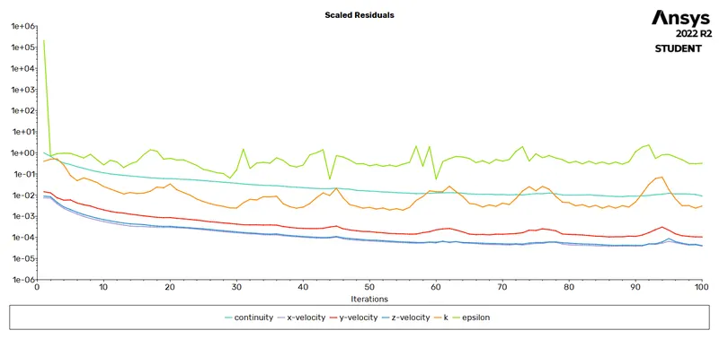
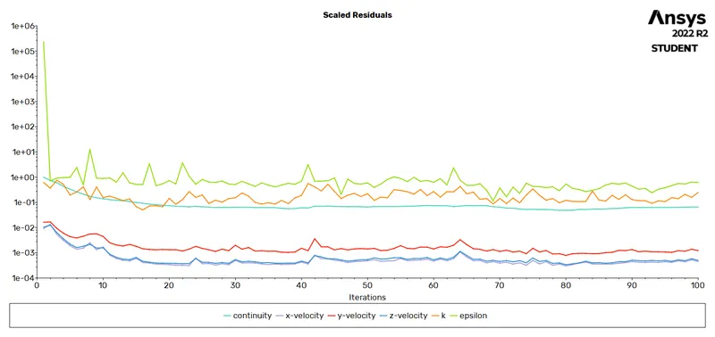
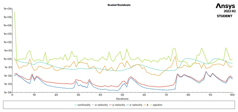
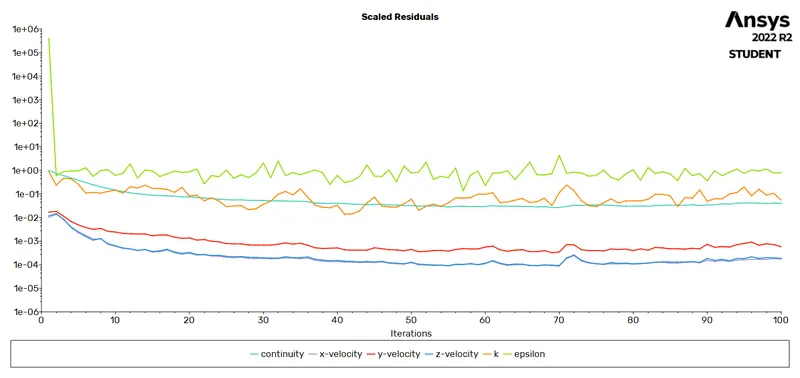
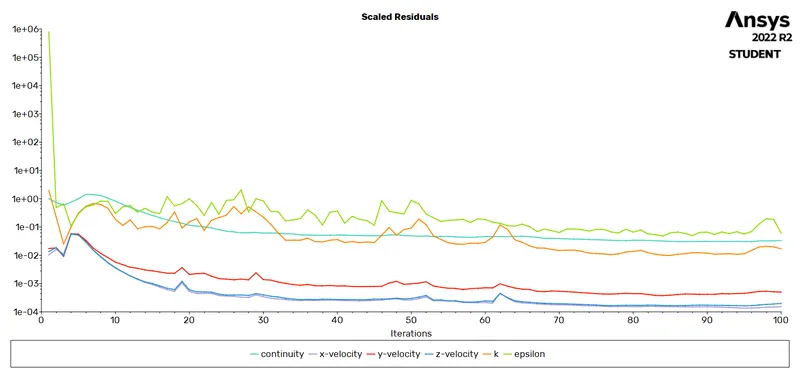
Solver settings were initialized and calculation was run for a certain number of iterations till the convergence.
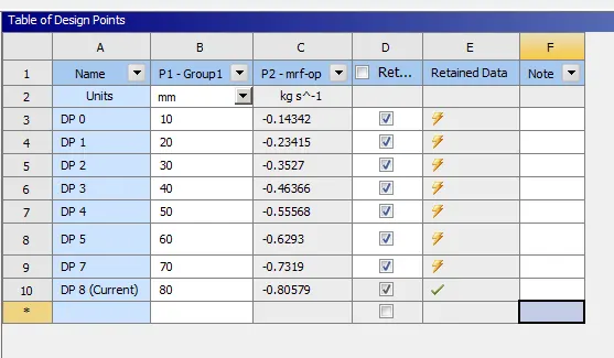
As the input parameter to lift the gate disc had already been initialized, all that was left to do was adjust the distance between the gate disc and the bottom of the flange coupling in the 'Table of Design Points' under the 'Parameters Cell' as shown below for remaining seven simulations. Additionally shown was the calculated value for the mass flow rate at the outlet.
 |
|
Case No. |
Plots |
|
|
Scaled Residuals |
Mass Flow Rate |
|
|
1 |
|
|
|
2 |
|
|
|
3 |
|
|
|
4 |
|
|
|
5 |
|
|
|
6 |
|
|
|
7 |
|
|
|
8 |
|
|
POST-PROCESSING -
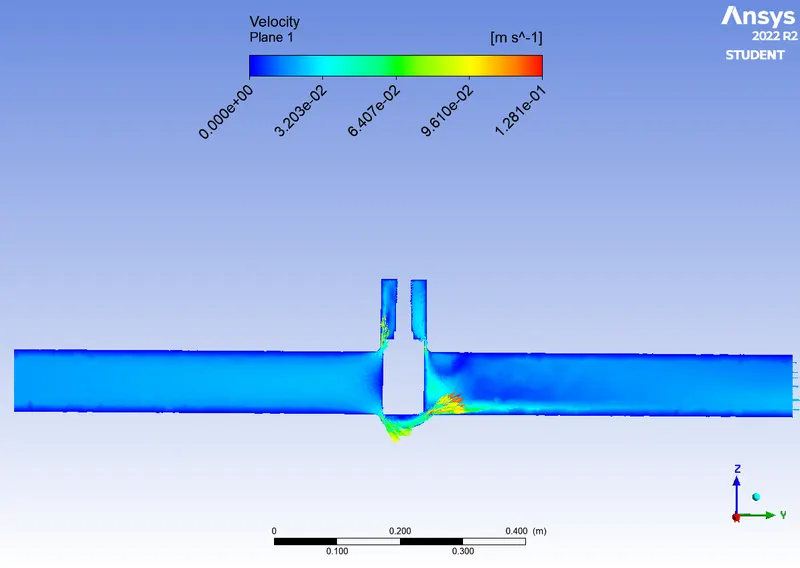
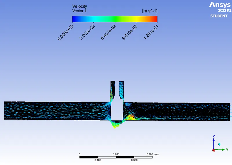
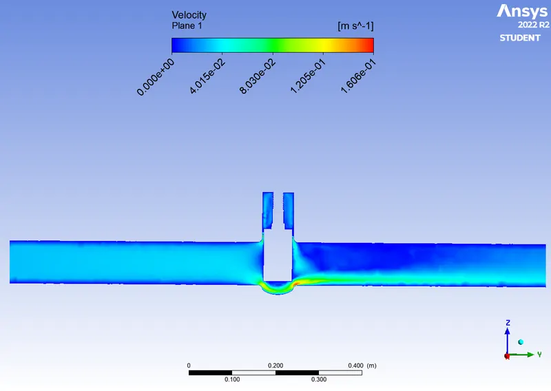
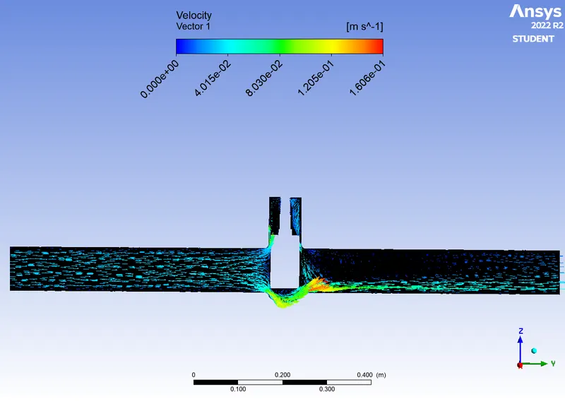
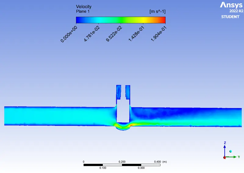
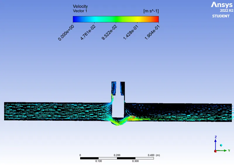
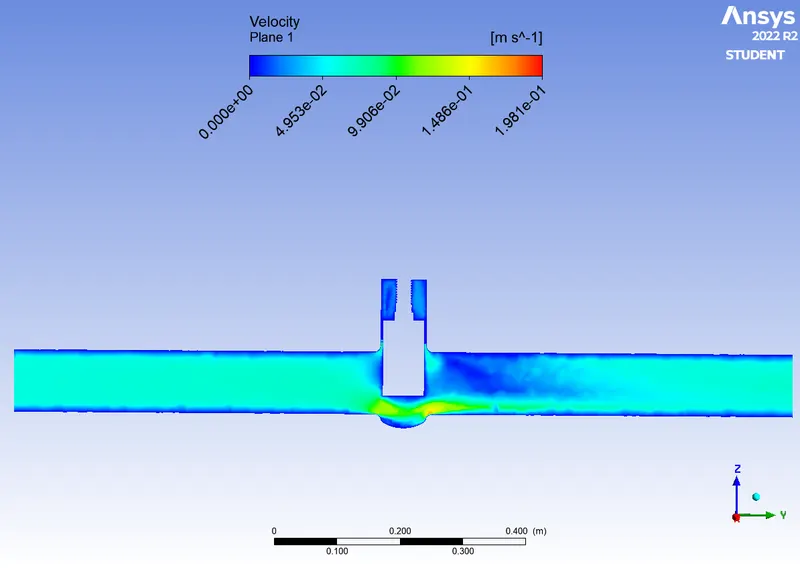
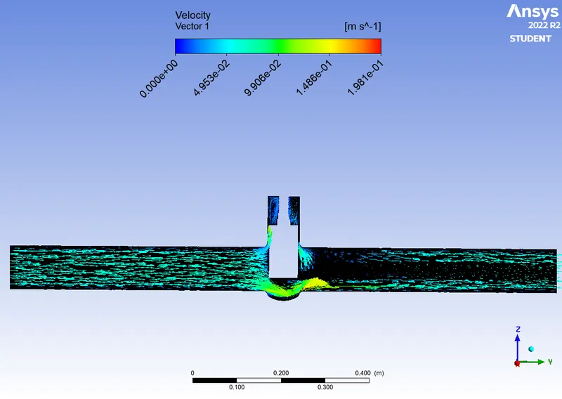
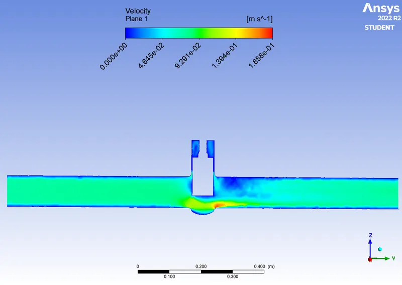
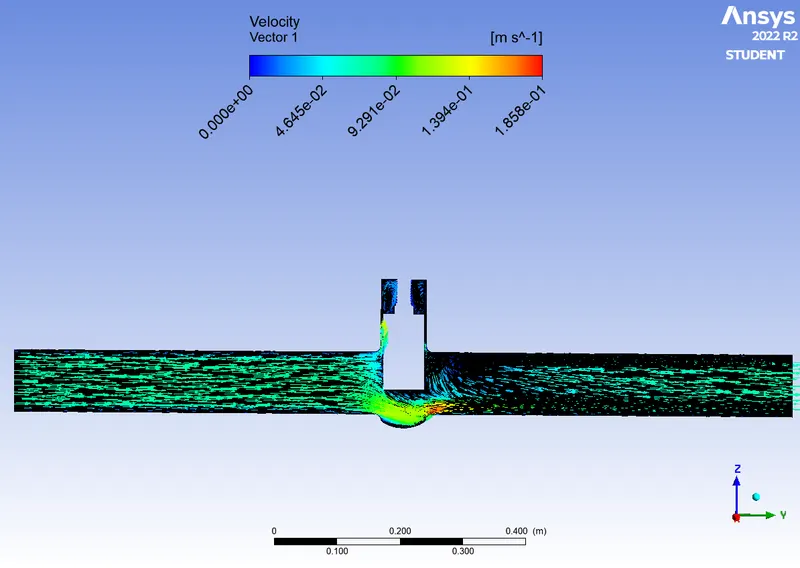
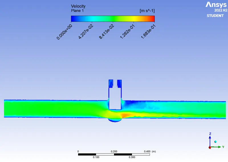
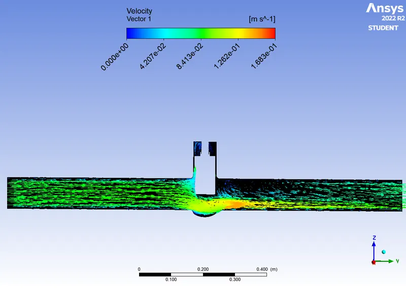
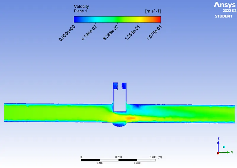
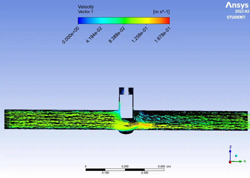
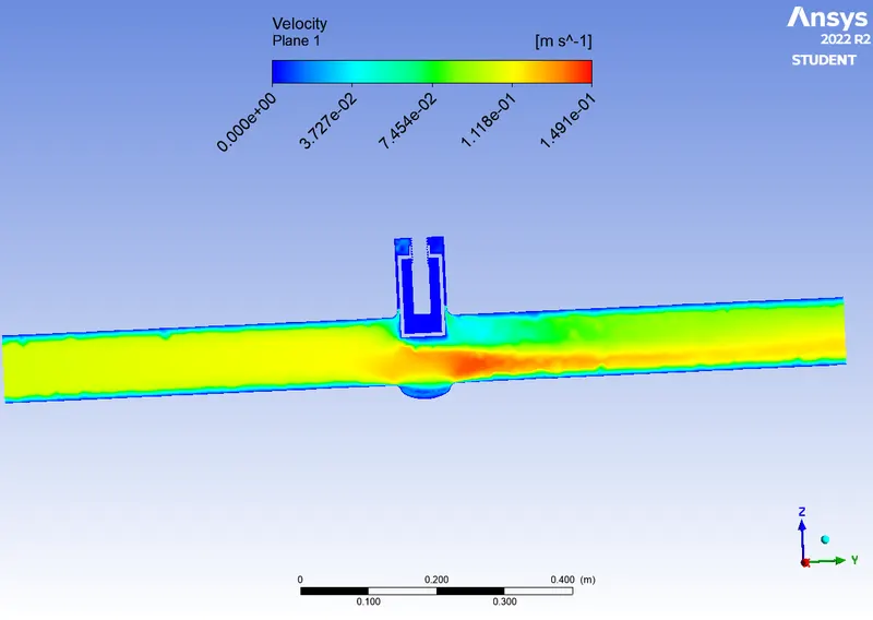
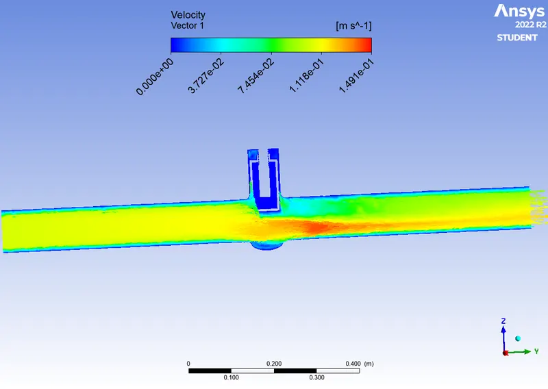
Over a plane parallel to the fluid flow, velocity and velocity vector contours were plotted.
Note: The animation feature in post-processing cannot be used while performing simulation with any input condition parameterized. Otherwise, the simulation must be performed individually.
RESULTS -
|
Case No. |
Contours |
|
|
Velocity |
Velocity Vector |
|
|
1 |
|
|
|
2 |
|
|
|
3 |
|
|
|
4 |
|
|
|
5 |
|
|
|
6 |
|
|
|
7 |
|
|
|
8 |
|
|
CONCLUSION -
The values of the Flow Factor (Kv) and Flow Coefficient (Cv) calculated from (1), (2) & (3) for various positions of the gate disc are shown in the table below;
|
Case |
Gate Disc Lift (mm) |
Inlet Pressure (Pa) |
Pressure Drop (bar) |
Mass Flow Rate (kg/s) |
Volumetric Flow Rate (m3/hr) |
Flow Factor (Kv) |
Flow Coefficient (Cv) |
|
1 |
10 |
10 |
0.0001 |
0.14 |
0.504 |
50.4 |
58.26 |
|
2 |
20 |
10 |
0.0001 |
0.23 |
0.828 |
82.8 |
95.71 |
|
3 |
30 |
10 |
0.0001 |
0.35 |
1.26 |
126 |
145.65 |
|
4 |
40 |
10 |
0.0001 |
0.46 |
1.656 |
165.6 |
191.43 |
|
5 |
50 |
10 |
0.0001 |
0.55 |
1.98 |
198 |
228.88 |
|
6 |
60 |
10 |
0.0001 |
0.63 |
2.268 |
226.8 |
262.18 |
|
7 |
70 |
10 |
0.0001 |
0.73 |
2.628 |
262.8 |
303.79 |
|
8 |
80 |
10 |
0.0001 |
0.80 |
2.88 |
288 |
332.93 |
 |
 |
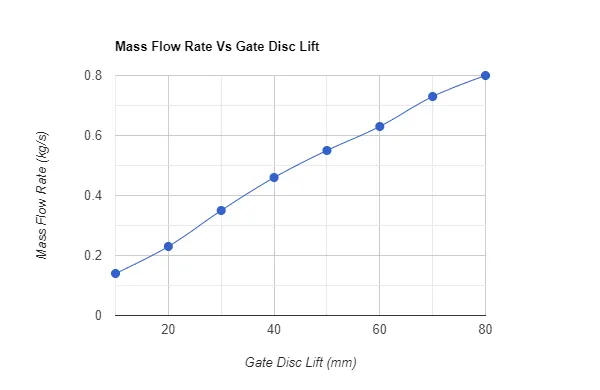
- With an increase in gate disc lift, the mass flow rate value at the outlet gradually increases.
- The mass flow rate value increases as the lift value decreases.
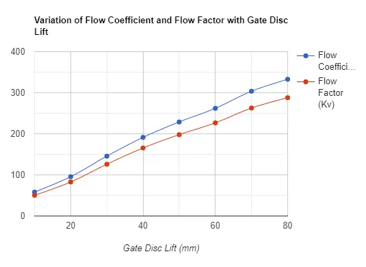
- The values of flow coefficient (Cv) and flow factor (Kv) also increase with an increase in gate disc lift.
- The values of Cv and Kv can therefore be deduced to be directly proportional to the mass flow rate at the outlet.
Thus, the parametric study of flow through a gate valve was accomplished using Ansys Fluent.