Project 1 : CFD Meshing for Tesla Cyber Truck
QUESTION -
For the given geometry of the Tesla Cyber Truck, check and solve all geometrical errors and Assign appropriate PIDs. Perform meshing with the suitable Target length and element Quality criteria.
Take target lengths for different components and quality criteria according to the system capacity.
Create a thorough report outlining the entire procedure. Include the concepts you studied as well.
Final Geometry File: https://drive.google.com/file/d/1p70kaKXl7RaDjkL2xjKGHnWpHAPKGV7R/view?usp=sharing
ANSWER -
Aim -
To surface mesh and perform topo clean-up on the provided "Tesla Cyber Truck" model in the ANSA pre-processor under the specified conditions. Additionally, a fluid domain must be created and meshed for the model's external flow analysis.
In the automotive industry, ANSA is a well-liked computer-aided engineering tool for CFD and Finite Element Analysis.
Procedure -
We are concerned about the geometry's "External Flow Analysis." As a result, we will concentrate on cleaning up the external geometry, though we can also include the internal volume because doing so will extend and raise the cost of our computations. Therefore, including the internal volume is basically inefficient. The geometry will eventually be made into a single volume.
Additionally, we would build a wind tunnel, also known as a "fluid domain," towards the conclusion of mesh production in order to analyze the external flow of our geometry. In fact, we would create a surface mesh over it.
There would be four major procedures to accomplish CFD Meshing for Tesla Cyber Truck.
- Topo Clean-up
- Creating and Assigning PIDs
- Surface Mesh Generation (with Quality Criteria)
- Constructing a fluid domain and surface mesh over it
Steps -
- TOPO CLEAN-UP:
Import the geometry. Change the geometry's "Wireframe display" mode to "Shadow display" mode to carry out the appropriate actions on it. By default, we are working in "Topo Deck" here.
Click "Topo" & fix the "Resolution" of the geometry, if required.
Note - After error cleanup, "Topo" helps unite the faces that were not joined properly. Thus, the "Topo" module, located under the "Faces" module button, aids in the automatic correction of minor geometry problems.
Before continuing, a surface that is missing needs to be fixed. 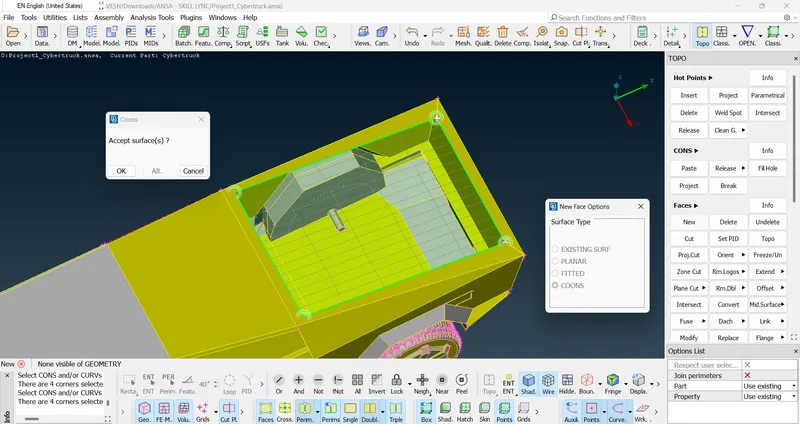
Now, the geometry is ready to be corrected and cleared away.
An entire vehicle is visible on our interface. There are two options for moving forward:
One can work on the full geometry from the Topo clean-up to the development of the surface mesh, or one can partition the geometry into two equal halves and work on each half until the mesh generation stage, after which the geometry is mirrored to create the other identical half. The former method would require more computational time during the mesh generation phase, and there is a chance that the system could hang. So, as we did in "CFD Meshing for BMW Car," we will use the latter approach.
One can see that there is no partition line or cones that divide geometry into two equal halves. Hence, we will use the "Plane Cut" tool under the "Faces" Module. One may use the "Cut" or "Project Cut" tool here. However, "Plane Cut" would not consume time and will help create the new face easily. 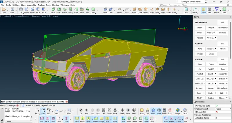
Thus, we deleted the half geometry without facing any issues. 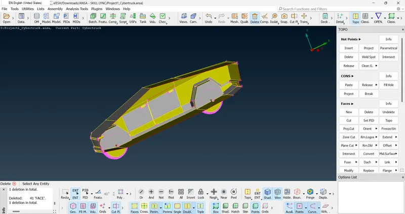
First, we will clear all the single cones, and then we will check for errors in our geometry.
Tool Bar > Checks > Checks Manager > Geometry_Checks > Execute
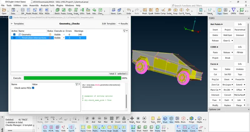
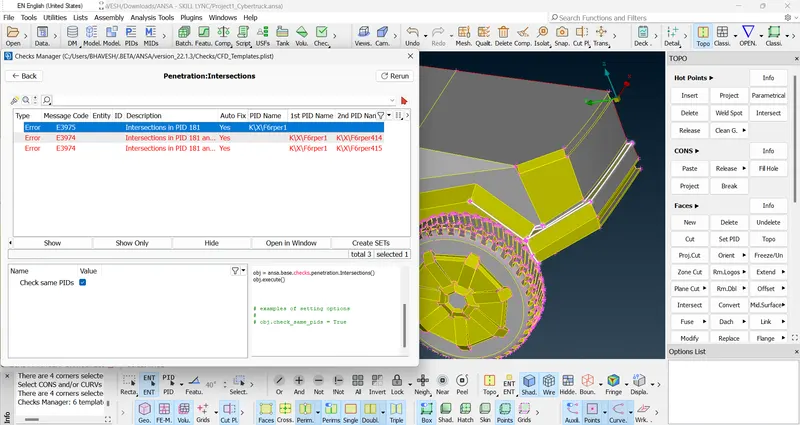
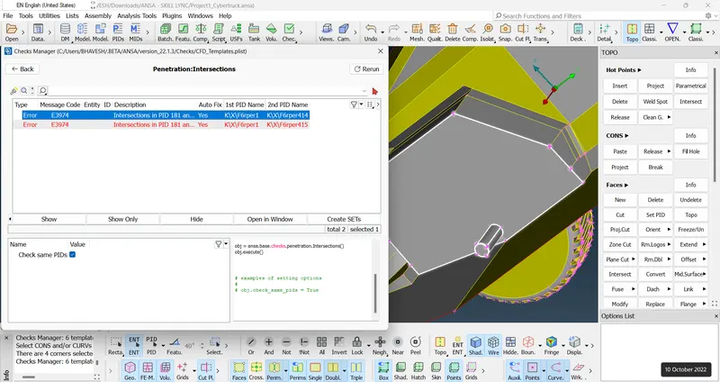
We found three major intersection errors. Using various tools under "Module Buttons Group" we will resolve these errors in our geometry.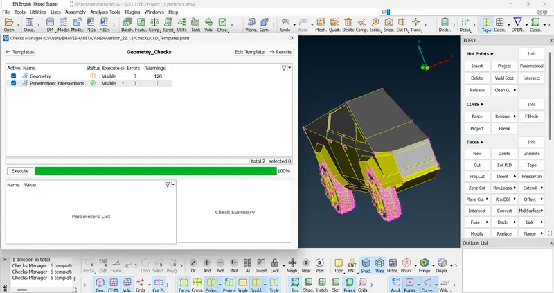
Thus, all the errors in the geometry are cleared & Topo clean-up is done.
- Creating and Assigning PIDs:
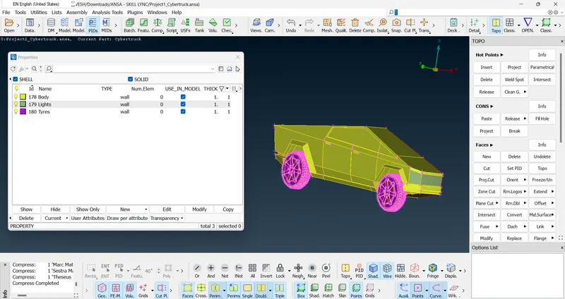
We will create three PIDs as 'Body', 'Lights' & 'Tyres'. Use the "Compress" tool to delete unnecessary PIDs.
- Surface Mesh Generation (with Quality Criteria):
The target length that we will use for the assigned PIDs are;
- Lights - 2 mm
- Tyres - 3 mm
- Body - 4 mm
We will turn ON the necessary Quality Criteria before performing the surface mesh. Deselect all the other parameters.
| Sr. No. | Quality Parameter | Value Assigned |
| 1) | Skewness | 0.5 |
| 2) | Minimum Length | 0.2 |
| 3) | Maximum Length | 6 |
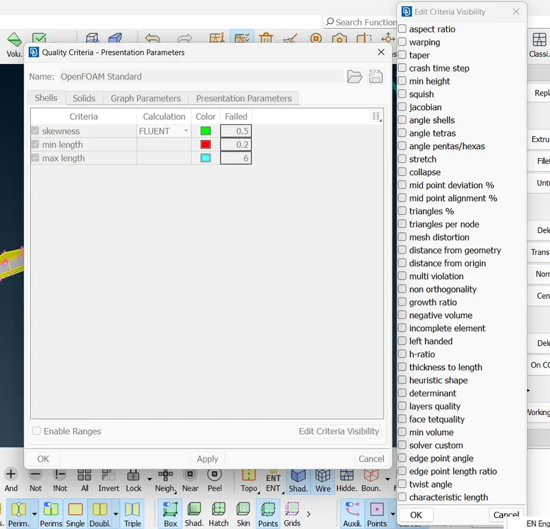
Moving toward surface mesh generation click the "Classic Mesh" deck. For the quality criteria to remain visible on the screen, select the "Hidden" tool from the toolbar.
We will mesh each component one after the other because of the varying target lengths. However, certain surfaces may not be mesh when we examine the mesh created over the full geometry. These unmeshed surfaces are produced along the perimeters of the components as a result of the variable target lengths of each individual component. To avoid this mishappening, the mesh formed over the chosen geometry will be frozen using the "Freeze/Unfreeze" module button in the "Macros" module button group as soon as each component's mesh is generated. This will prevent the mesh from being lost or deleted when meshing the other components.
Classic Mesh > Macros > Freeze > Left click > select the visible geometry
Repeat this tool after the mesh generation of every component.
Once every component is done with mesh generation, click 'All" and use the same "Freeze/Unfreeze" module button to unfreeze the entire geometry for further processing once the mesh generation of all the components is complete.
Classic Mesh > Macros > Freeze > Right click > select the entire geometry.
Later, for Mesh generation, we will follow three simple steps;
1. Toggle the toolbar to "Mesh Parameters." Choose the "CFD Mesh" mesh type and the "Tria" element type from the "Basic" menu. Include the minimum and maximum target lengths. Press OK.
| Sr. No. | Component | Target Length Chosen | Minimum Target Length Assigned | Maximum Target Length Assigned |
| 1) | Lights | 2 mm | 0.5 mm | 3 mm |
| 2) | Tyres | 3 mm | 2 mm | 4 mm |
| 3) | Body | 4 mm | 2 mm | 5 mm |
In this case, we chose CFD mesh over general mesh because the former produces more precise results. General mesh is also an option, and the results won't be inaccurate.
2. Perimeter Module > Spacing > Auto CFD > Perimeters > Select all geometry with the middle click and then click OK, followed by Macros > Select all geometry with the middle click and then click OK.
3. Mesh Generation Module > CFD > Visible
Also, during the mesh generation, one may find a certain number of "Off" elements (bad elements) in the geometry as we have turned ON the quality criteria. In the question, it is mentioned that there should be no off elements. In order to clear this quality criteria, Right-click "Off elements", click "Improve" and try to 'Reconstruct' or 'Reshape' the elements so that the off elements get improved and turn into desirable elements. One may use 'Smooth' or 'Fix Quality' options too, but it is preferred to use 'Reconstruct' or 'Reshape'; first.
In case, if the "Improve" option fails to clear off elements, then one can move the grids of off elements to fix the issueas;
Mesh deck > Grids > Move > OK
Always mesh the lower target length components first, working your way up to the higher target length components towards the end, to ensure that the geometry adapts to the mesh transition well and aids in the right body capture.
Thus, Mesh generation, with quality criteria, is done.
To create the other identical half of the geometry, it is now necessary to mirror the geometry.
Transform > Copy > Entities > choose all of the geometry > select "Symmetry" > choose "3 Points Plane" choose any three random spots on the geometry's edge > OK > Apply > Finish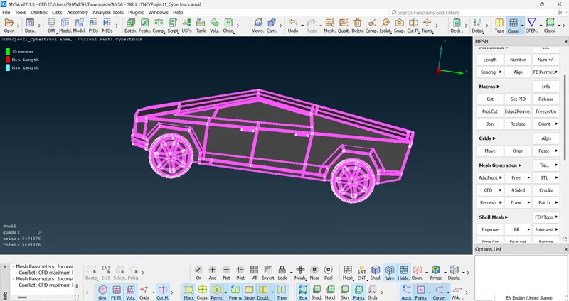
- Constructing a fluid domain and surface mesh over it:
Additionally, it is required to build a wind tunnel that serves as a fluid domain for the analysis of the external flow over the geometry. One top face, one bottom face and four side faces make up a wind tunnel (two at the rear and front ends & two at the left and right ends). Let 'x' represent the vehicle's length (from the rear end to the front end). The value of "x" after measurement was done was "around "5800 mm".
Several standards must be followed when constructing the wind tunnel;
The gap between the vehicle and the top of the wind tunnel must be at least three times the vehicle's length. There must be more space than or equal to "x" between the car and the two left and right ends. The distance between the car's front and rear ends and the wind tunnel should be larger than or equal to "4x" and "6x," respectively. It is ideal to leave enough space between the vehicle and the bottom of the wind tunnel for them not to cross. As a result, a wind tunnel was built utilizing a variety of tools, including 'Points', 'Curves', 'Face offset', etc.
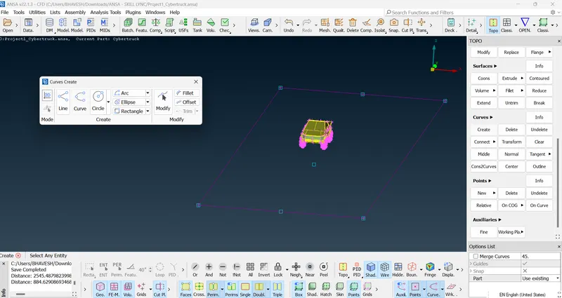
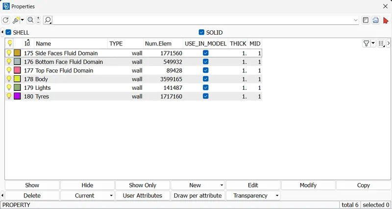
Without regard to quality standards, this wind tunnel must mesh with the following target lengths:
20 mm on the bottom face,
100 mm across the top,
For side faces, we need to have a 'Growing Mesh'. It will transit from the bottom face to the top face.
Mesh deck > Perimeters > Spacing > Manual > Select all four side face edges with the following settings: Growth Factor = 1.2, Dstart = 20, Dlimit = 100, then click OK.
Thus, fluid domain creation and meshing, as well as surface mesh generation for the Tesla Cyber Truck, are carried out.
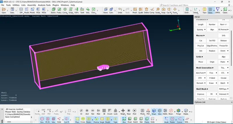
Let's check for any errors in our final work. 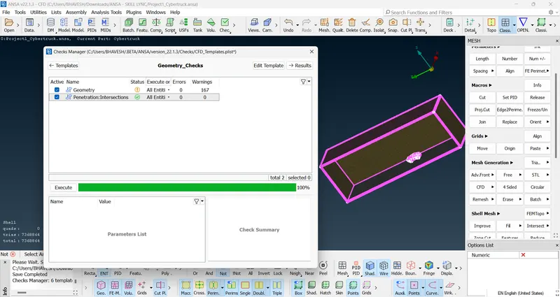
Learning Outcomes -
Learned how to use a variety of new tools to perform operations on a geometry that was provided. The wind tunnel's construction and meshing were new.
Result -
According to the conditions, geometry was modified, and appropriate meshing was carried out.
Conclusion -
A complete report of the entire procedure was mentioned.