Week 9 - Parametric study on Gate valve.
Aim :-
- Perform parametric study on gate valve by setting the opening from 10% to 80%
- Obtain the mass flow rates at the outlet for each design point.
- Calculate the flow coefficient and flow factor for each opening and plot the graph.
- Discuss the results of the mass flow rate and flow coefficient.
Gate valve :-
A gate valve, also known as a sluice valve, is a valve that opens by lifting a barrier (gate) out of the path of the fluid. Gate valves require very little space along the pipe axis and hardly restrict the flow of fluid when the gate is fully opened. The gate faces can be parallel but are most commonly wedge-shaped (in order to be able to apply pressure on the sealing surface).
Use :-
A gate valve is the most common type of valve that used in any process plant. It is a linear motion valve used to start or stop fluid flow. In service, these valves are either in fully open or fully closed position. When the gate valve is fully open, the disk of a gate valve is completely removed from the flow.
Procedure :-
Geometry :- import geometry from drive and first create Fluid volume by selecting inlet, outlet and upper edges of the “Bottom” part.
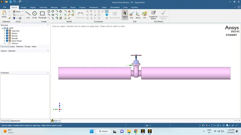
fluid volume :-
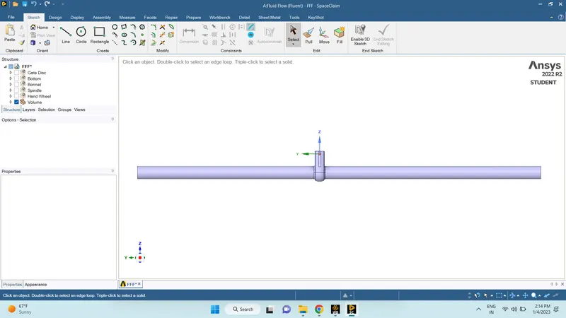
- After creating Fluid Volume, Hide all rest parts of Gate Valve and suppress it for Physics and save it for further process.
- Then open Mesh settings.
Mesh :-
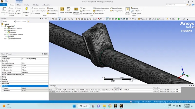
Setup :-
solver - pressure based
time - steady
gravity - -9.81 m/s^2 ( z direction)
viscous model - k-epsilon > realizable > Scalable Wall Functions
Boundry conditions -
inlet - pressure inet > 10 pa
Outlet -Pressure outlet > 0 pa
NOTE: Here we have taken Pressure for inlet 10 Pa, Typically for Pipe flow, pressure of 10 Pa is acceptable.
Go to Solution, and select Standard Initialization, and Initialize from Inlet.
Flow Coefficient:
The flow coefficient of a device is a relative measure of its efficiency at allowing fluid flow. It describes the relationship between the pressure drop across an orifice valve or other assembly and the corresponding flow rate.
Mathematically the flow coefficient Cv (or flow-capacity rating of valve) can be expressed as:
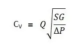
Where:
- Q is the rate of flow (expressed in US gallons per minute).
- SG is the specific gravity of the fluid (for water = 1).
- ΔP is the pressure drop across the valve (expressed in psi).
Flow Factor:
The metric equivalent flow factor is calculated using metric units:
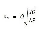
Where:
- Kv is the flow factor (expressed in). Q is the flow rate (expressed in cubic meters per hour.
- SG is the specific gravity of the fluid (for water = 1).
- ∆P is the differential pressure across the device (expressed in [bar]).
Kv can be calculated from Cv using the equation as given below:
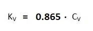
The kv factor of a valve indicates "The water flow in m3/h, at a pressure drop across the valve of 1 kgf /cm2 when the valve is completely open.
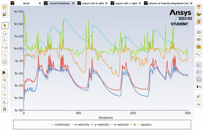
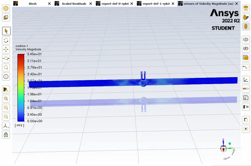
when lift open 10 mm
residuals -
Contours :-
Mass Flow Rate :-
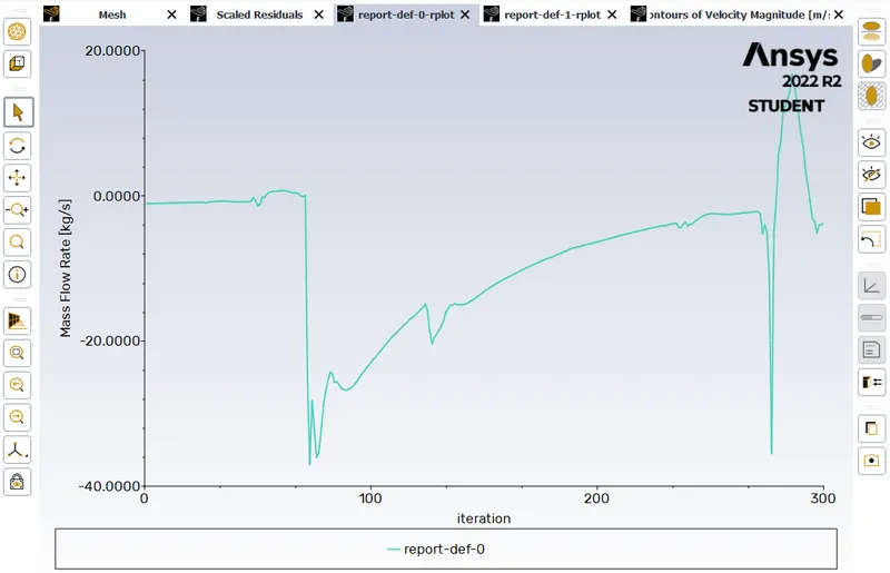
When lift at 20 mm :-
Residuals :-
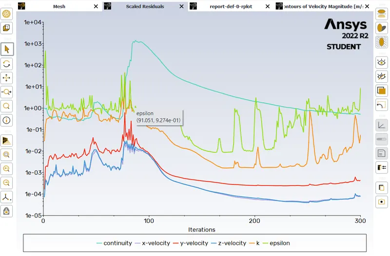
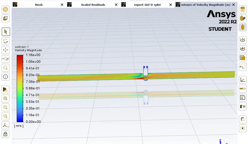
Contours :-
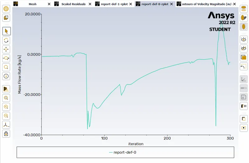
Mass Flow Rate :-
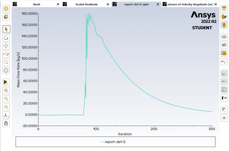
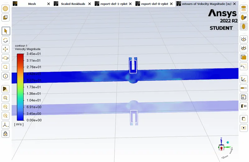
When lift at 30 mm :-
Contours :-
Mass Flow Rate:-
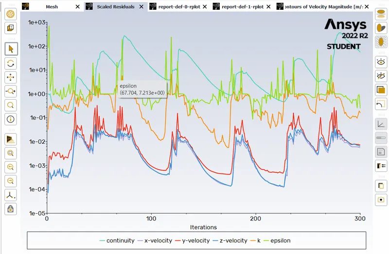
when lift at 40 mm :-
Residuals -
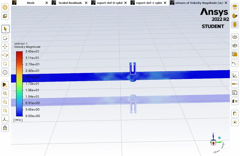
Velocity contour :-
Mass Flow Rate :-
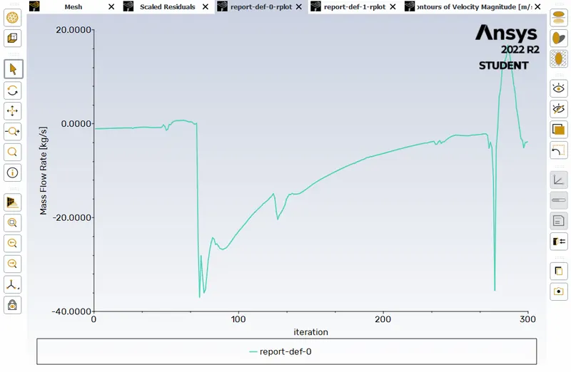
When lift at 50mm :-
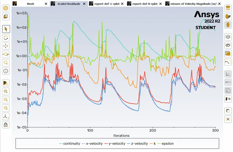
Velocity contour :-
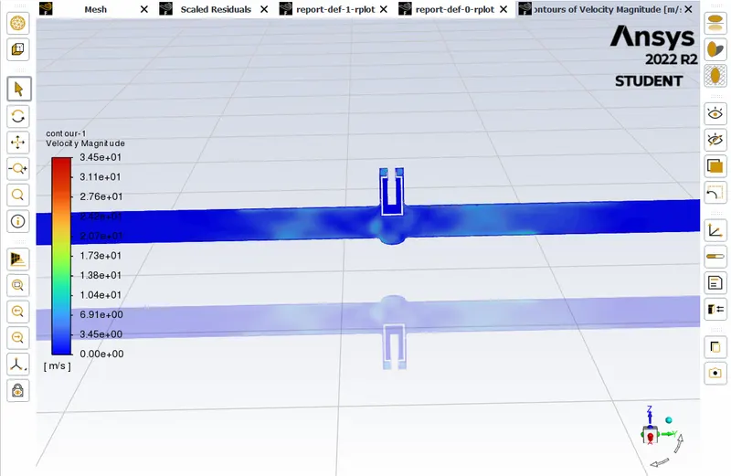
Mass Flow Rate :-
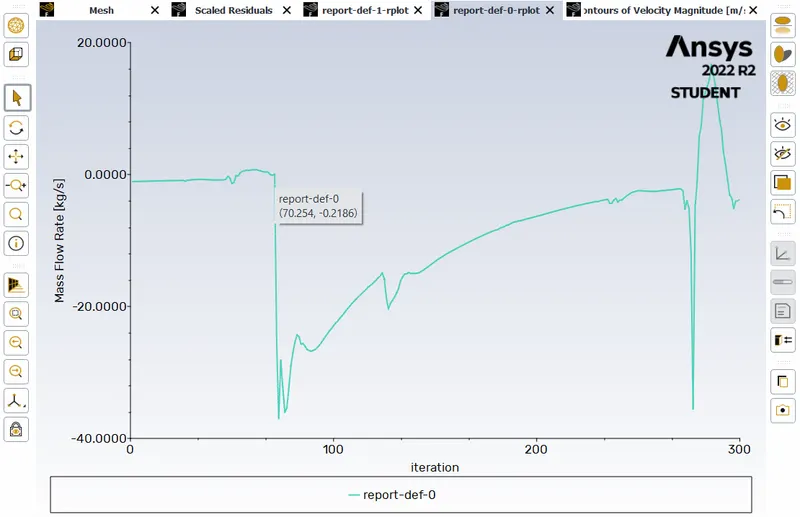
When lift at 60 mm :-
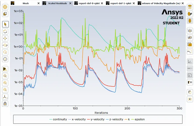
Velocity Contour :-
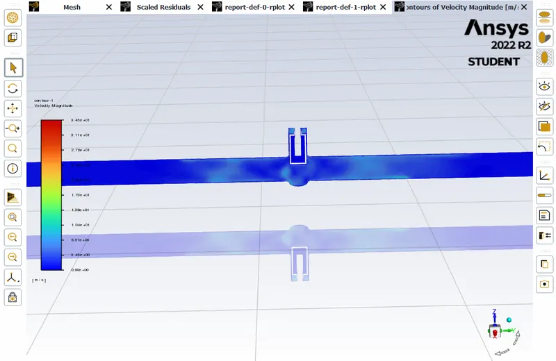
Mass Flow Rate :-
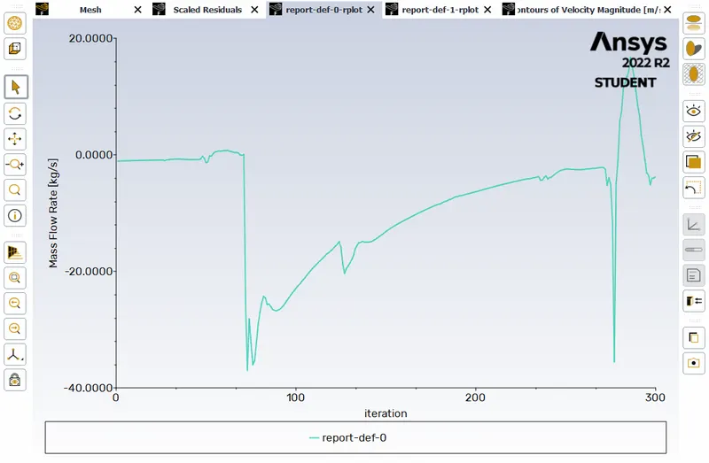
When lift at 70 mm :-
Residuals :-
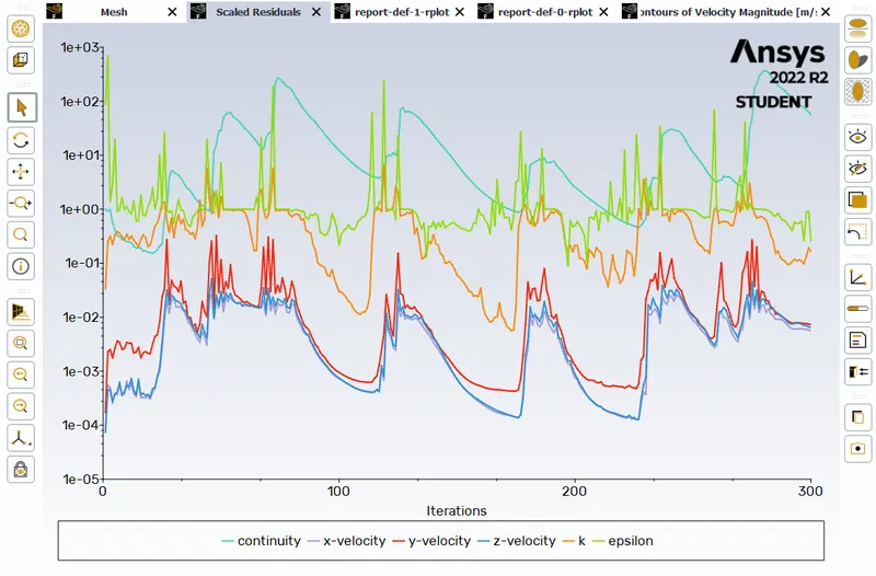
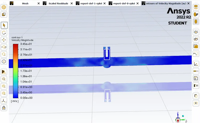
Velocity Contour :-
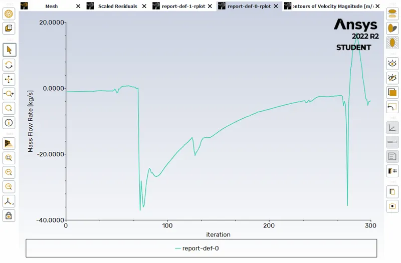
Mass Flow Rate :-
When lift at 80 mm :-
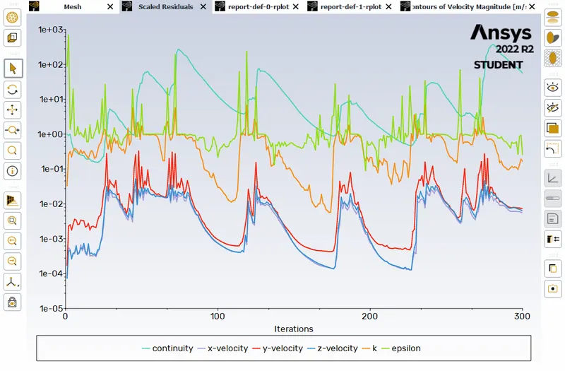
Residuals :-
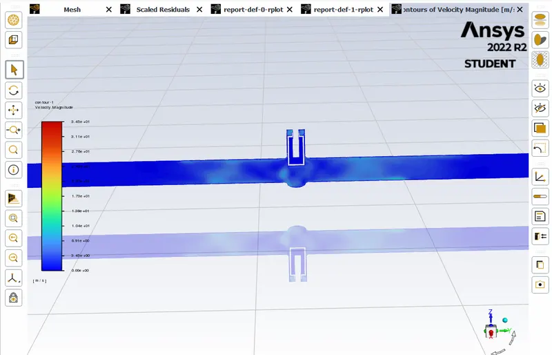
Velocity Contour :-
Mass Flow Rate :-
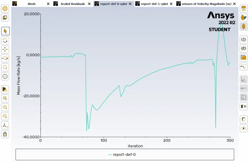
Overall Mass Flow Rate :-
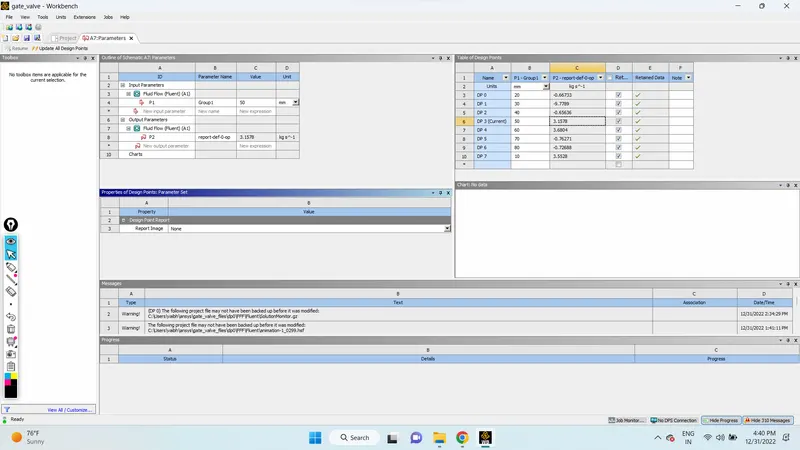
Flow Factor & flow coefficient :-
Pressure inlet: 10 Pa = 0.00145038 Psi
Specific Gravity: 1gm/cc, Density of water: 998.2kg/m^3
| gate disc lift in mm | Mass Flow rate kg/s | Flow Coefficient | Flow factor |
| 10 | 3.55 | -1.16277 | -1.0058 |
| 20 | -0.66733 | -17.0398 | -14.7394 |
| 30 | -9.7789 | -1.14371 | -0.98931 |
| 40 | -0.65636 | 5.50248 | 4.75965 |
| 50 | 3.1578 | 6.41312 | 5.5473 |
| 60 | 3.6804 | -1.32903 | -1.1496 |
| 70 | -0.76271 | 6.19077 | 5.35502 |
| 80 | -0.72688 | -1.162 | -1.0058 |
Result :-
1. The negative mass flow rate at the outlet indicates that the fluid is flowing out of the system.
2. The mass flow rate increases with an increase in the lift of the spindle.
3. The flow factor and flow coefficient are proprtional to each other.
Conclusion :-
The flow of water through a gate valve at different design points is accuratly simulated using a parametric study. The values of the mass flow rate at the outlet are also calculated and analyzed for all the design points.