Week 9 - Parametric study on Gate valve.
Aim
To perform a parametric study on the gate valve simulation by setting the valve opening from 10 % to 80 %.
Introduction
It works by lifting or pressing a rectangular or circular gate which connected by a stem by out of the path of the fluid by rotating the handle wheel clockwise and anticlockwise.
When the wheel with the handle is turned, the gate or wedge moves up and down across the flow of any fluid.
When you turn the handle wheel clockwise, steam and get move downward across the fluid flow, and the gate is squeezed between two seats.So that there is no fluid leakage when the valve is completely closed.
When you turn the handle Wheel anticlockwise, steam and fluid rise at the same time across the fluid flow. The valve is opened in the Chrome closed position, allowing fluid to flow through the Gate valve.
Gate will either open or closed.
Open gate means very low resistance or no resistance to the flow of any fluid.
Semi opening is not good because it causes erosion of the gate when fluid strikes.It also creates a lot of noise and vibration at the same time.
Modelling
The CAD model is imported into the spaceclaim using ansys fluid flow fluent workbench.
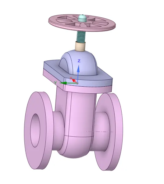
Bottom part is extruded at both sides of 500 mm with help of pull tool.
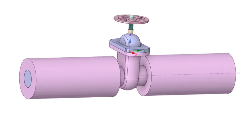
The fluid volume is extracted using the volume extract tool.
The gate disc is lifted by using move tool. For this under Groups option the parameter is created for the gate disc with ruler dimension of 10 mm and fluid volume is updated by clicking update volume body in the context.
For the different gate disc position the value of ruler dimension is changed.

Meshing
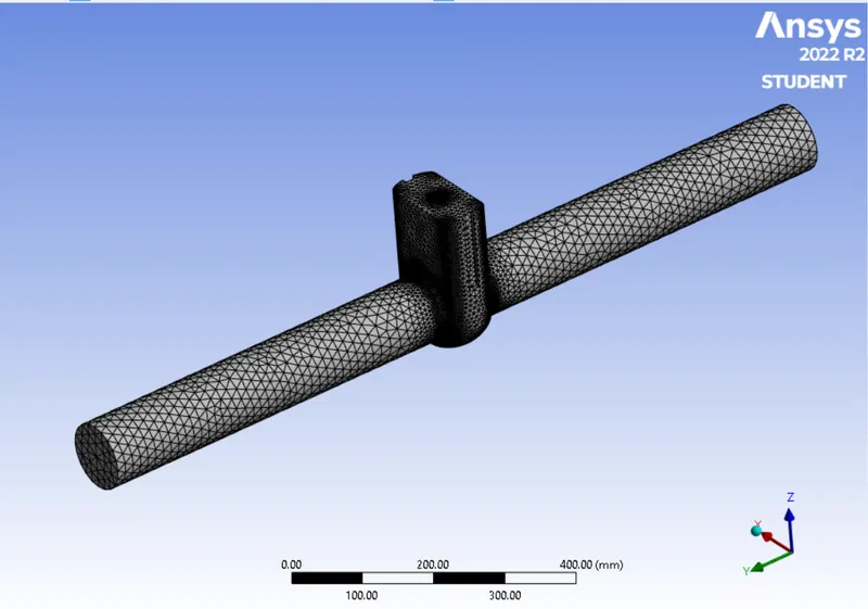
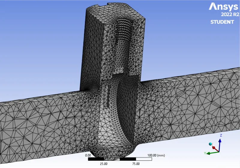
Mesh is generated with the tetrahedral elements.
Number of elements = 128773
Setting up physics
Solver
Solver type is pressure based and steady state solver.
Gravitational acceleration of -9.81 m/s2 is enabled in negative z direction.
Viscous model
Model : K-epsilon
K-epsilon model : RNG
RNG option : Swirl Dominated Flow
Near wall treatement : Standard Wall Functions
Material : Water
Boundary condition
Inlet
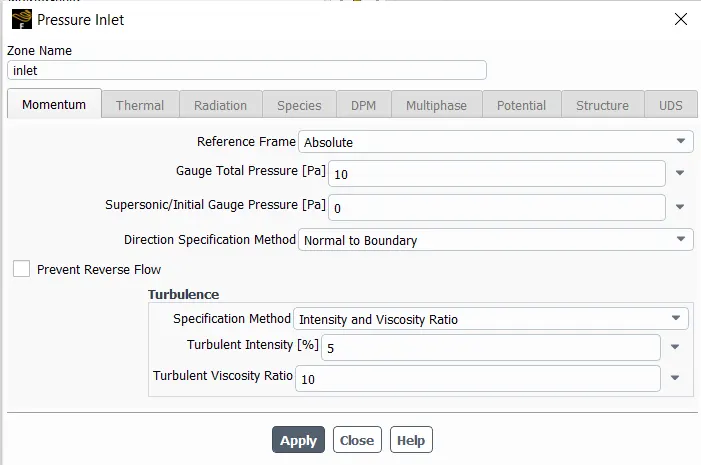
Type : Pressure inlet
Outlet
Type : Pressure outlet
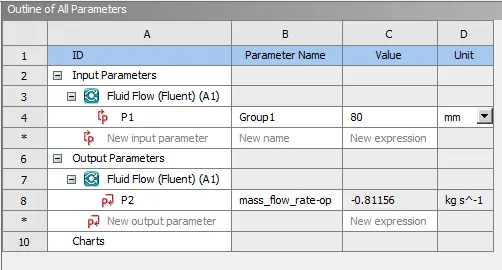
Report definitions of mass flow rate is defined and it is set as parameter.
The model is initialized using hybrid method.
Results
Case : 1 Gate valve lift of 10 mm
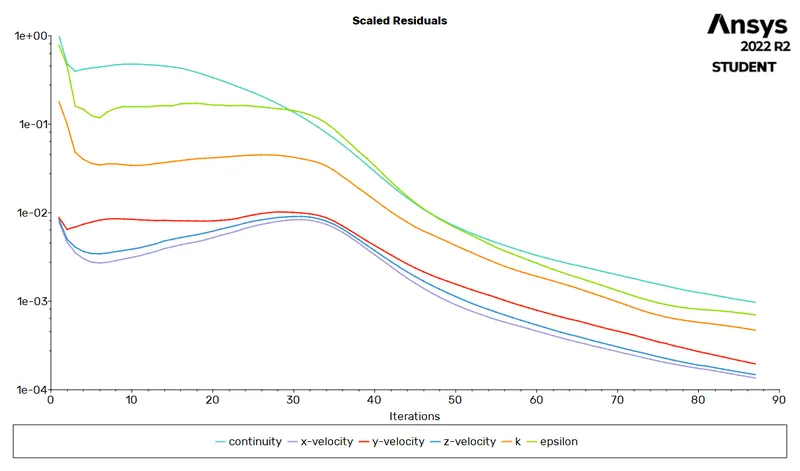
Residuals
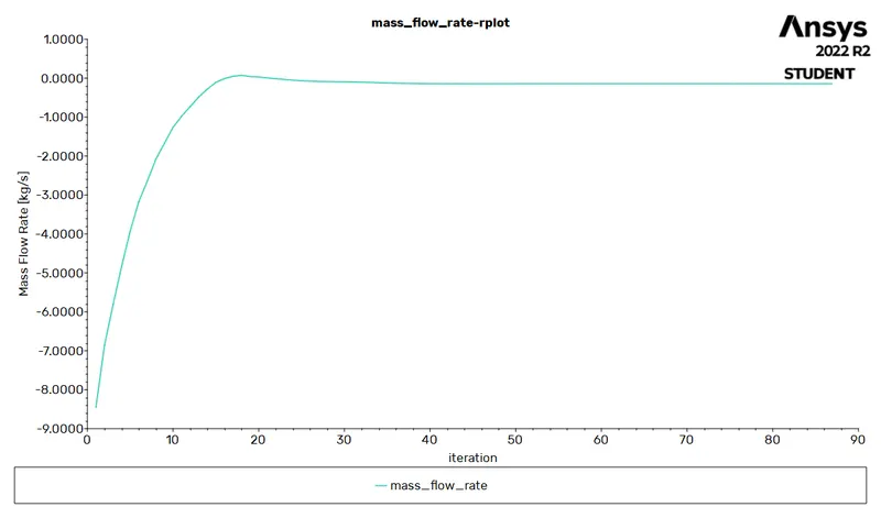
Mass flow rate at the outlet
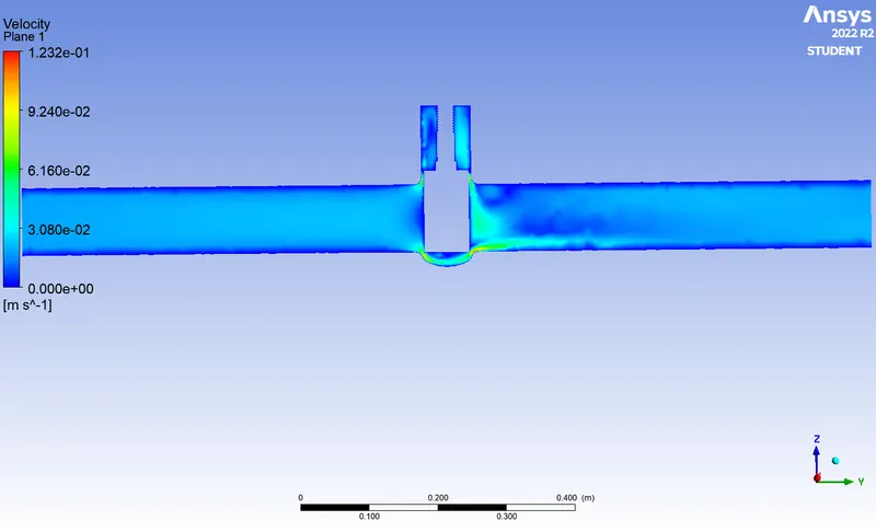
Velocity contour
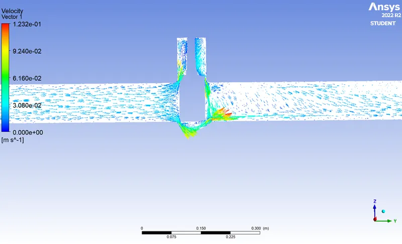
Velocity vector
Case : 2 Gate valve lift of 20 mm
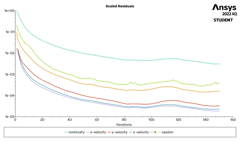
Residuals
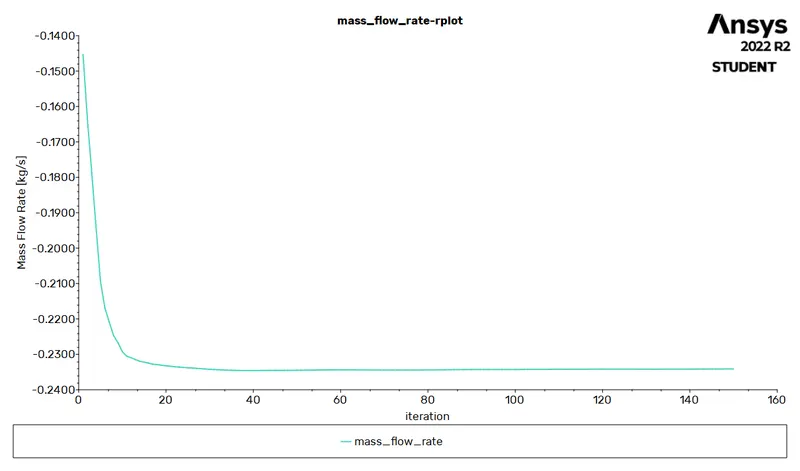
Mass flow rate at the outlet
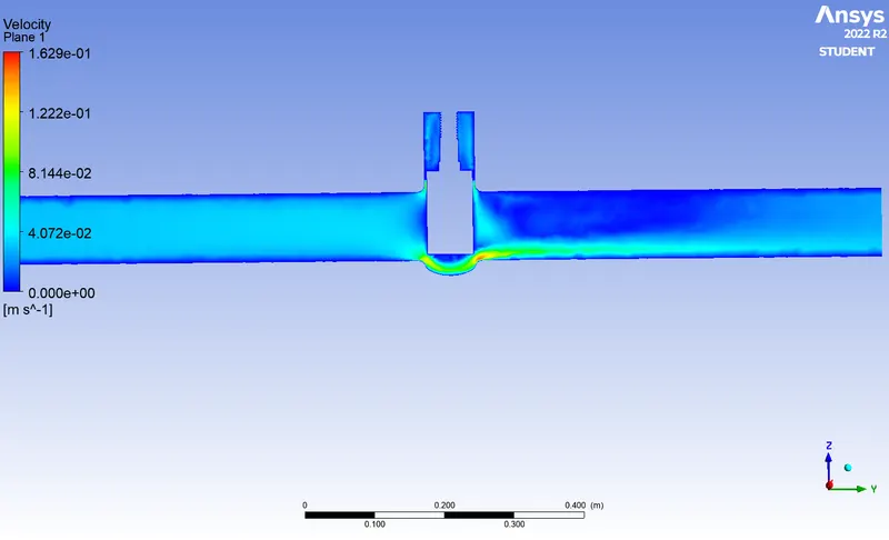
Velocity contour
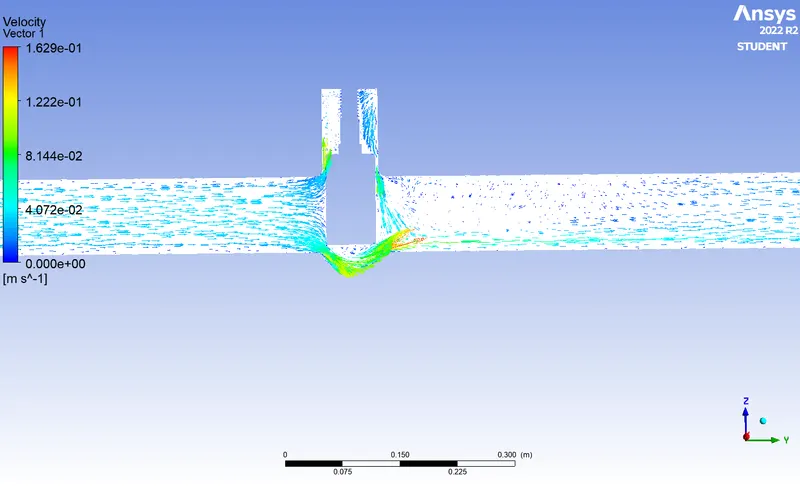
Velocity vector
Case : 3 Gate valve lift of 30 mm
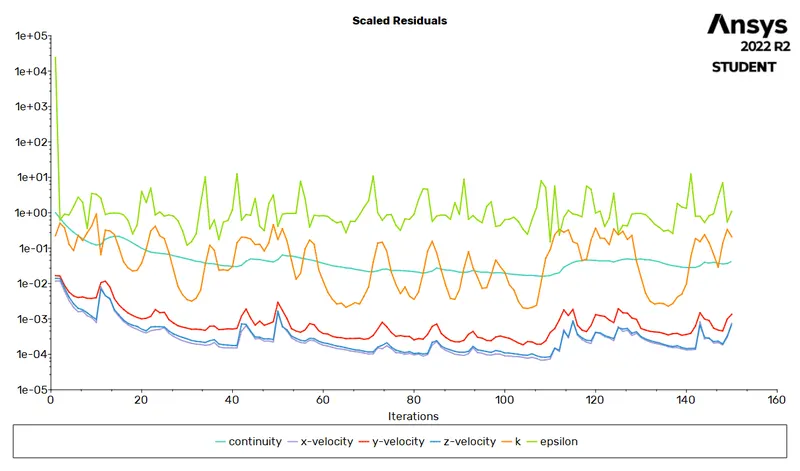
Residuals
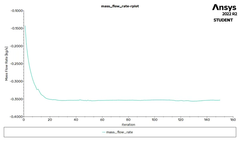
Mass flow rate at the outlet
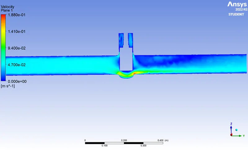
Velocity contour
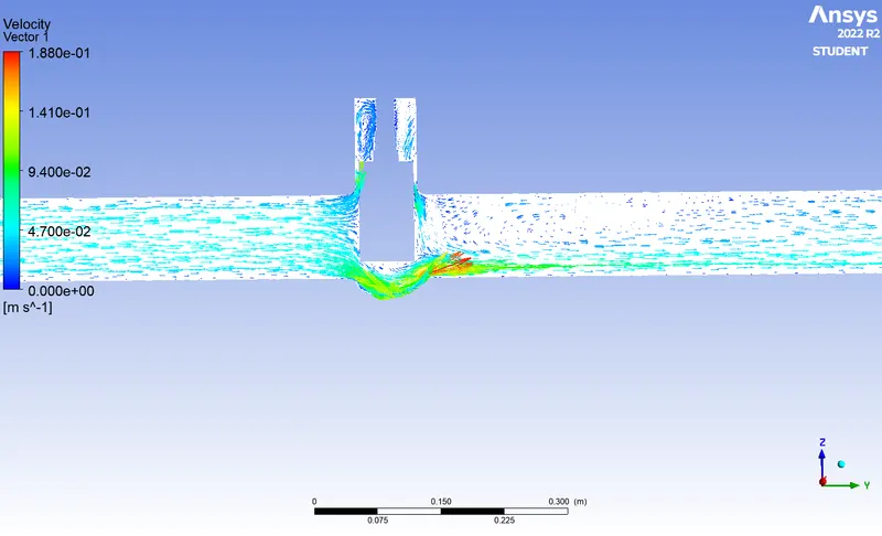
Velocity vector
Case : 4 Gate valve lift of 40 mm
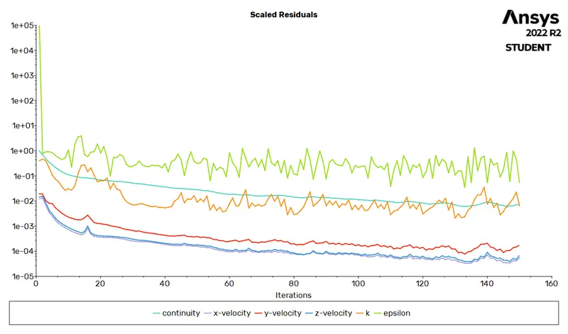
Residuals
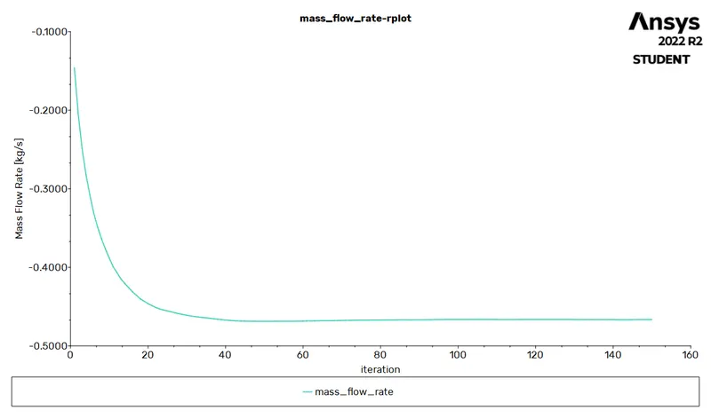
Mass flow rate at the outlet
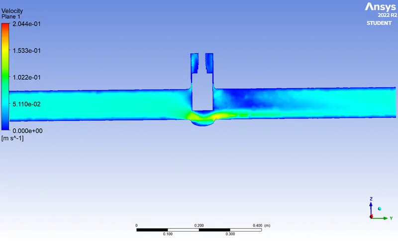
Velocity contour
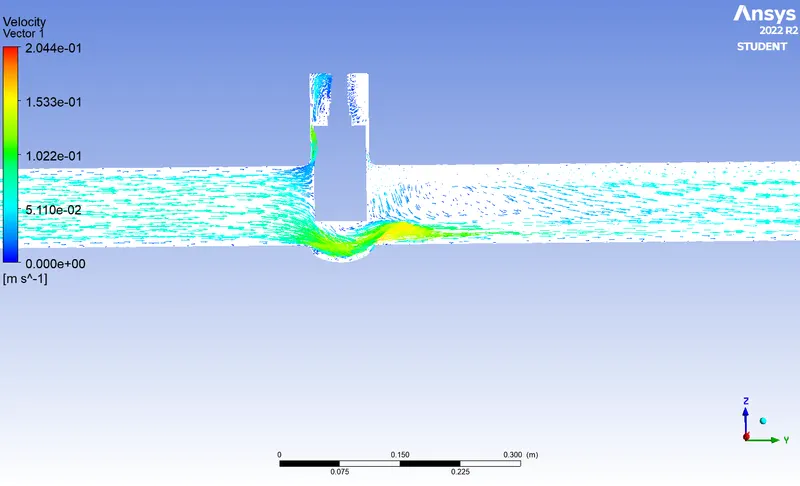
Velocity vector
Case : 5 Gate valve lift of 50 mm
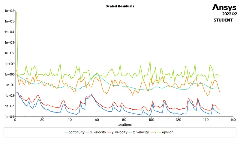
Residuals

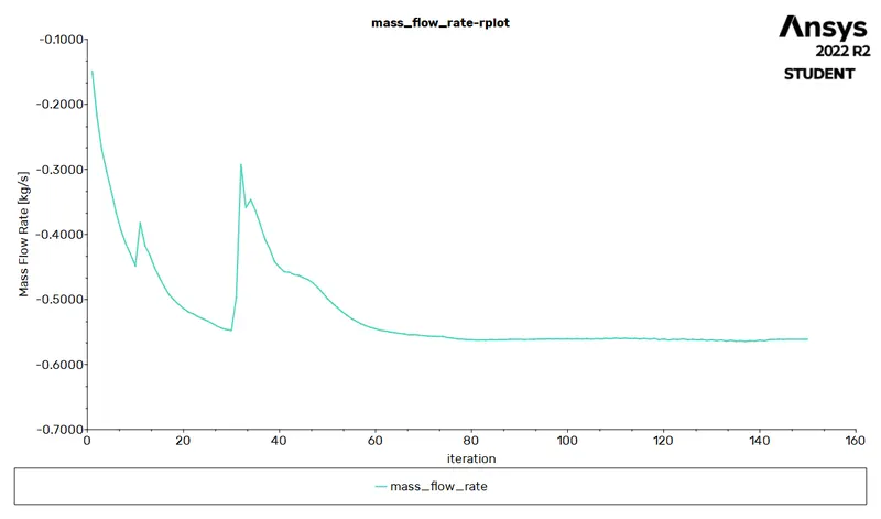
Mass flow rate at the outlet
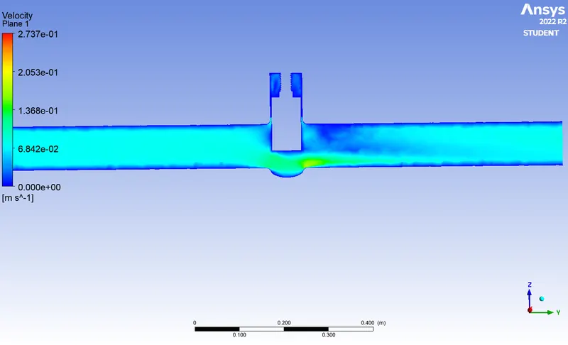
Velocity contour
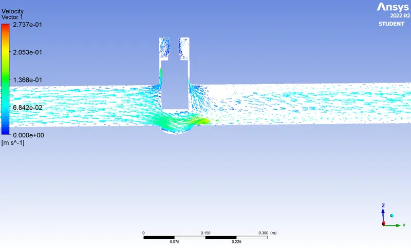
Velocity vector
Case : 6 Gate valve lift of 60 mm
Residuals
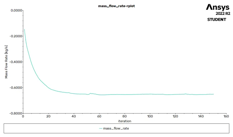
Mass flow rate at the outlet
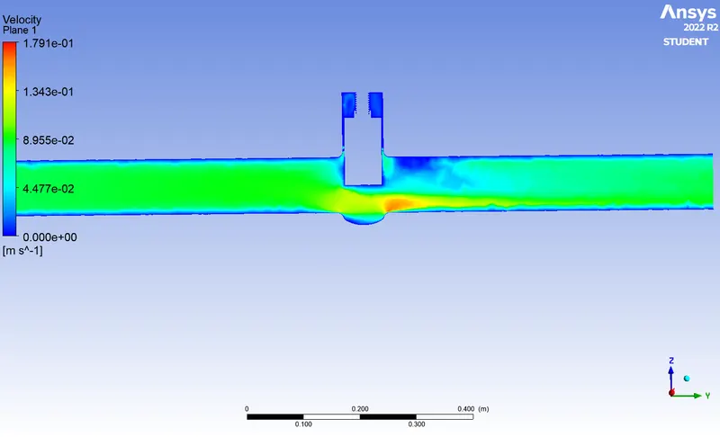
Velocity contour
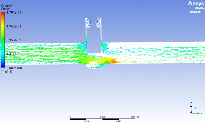
Velocity vector
Case : 7 Gate valve lift of 70 mm
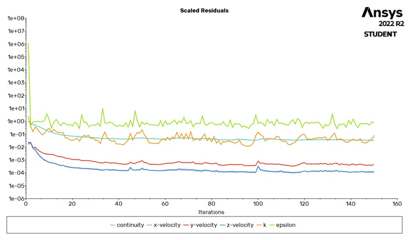
Residuals
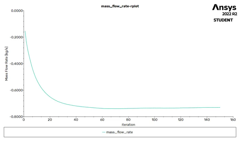
Mass flow rate at the outlet
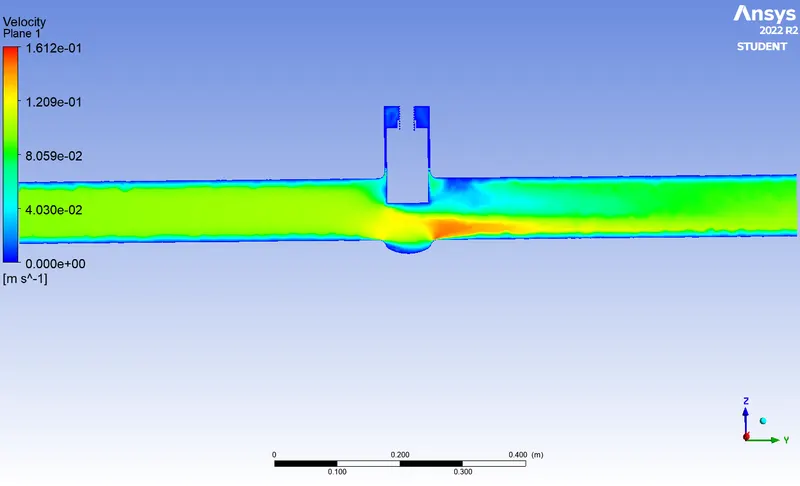
Velocity contour
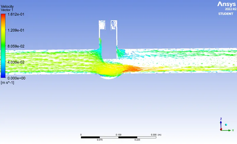
Velocity vector
Case : 8 Gate valve lift of 80 mm
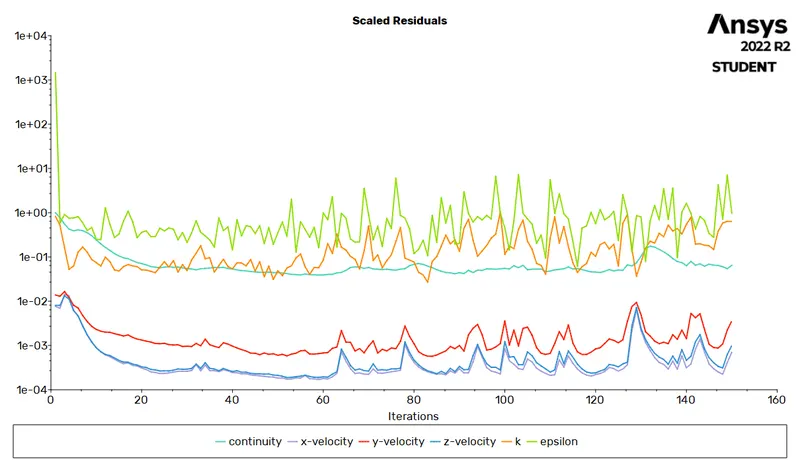
Residuals
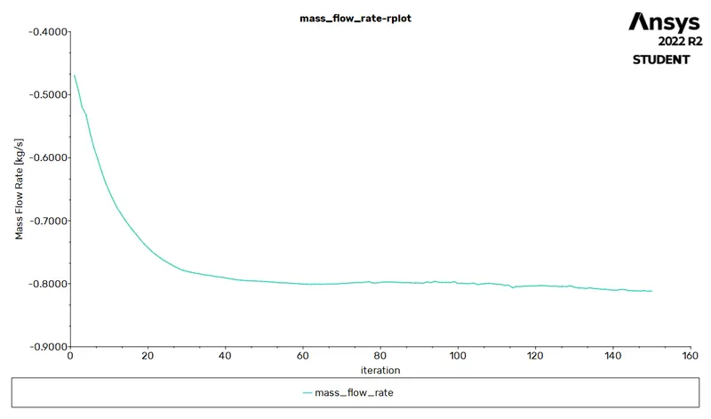
Mass flow rate at the outlet
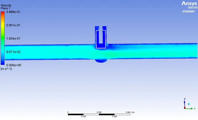
Velocity contour
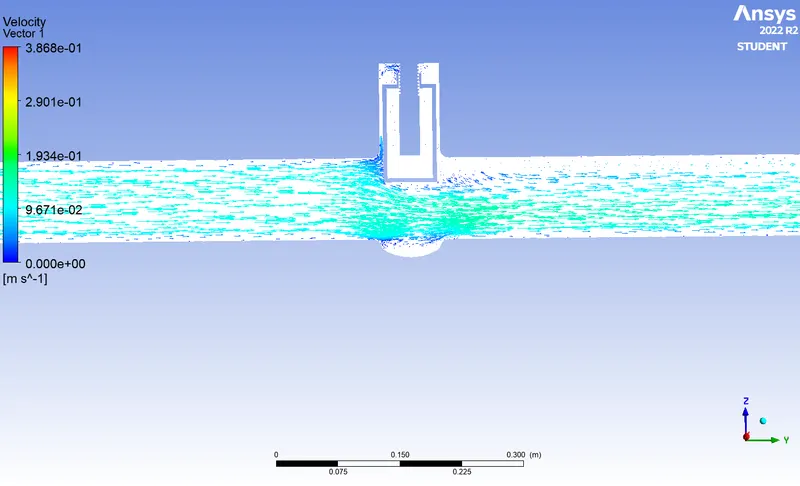
Velocity vector
Flow Coefficient and Flow Factor
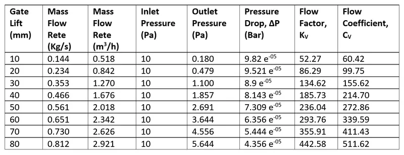
Flow Coefficient, CV is the volume of water in U.S. gallons per minute that passes through the valve at a pressure drop of 1 PSI at 68°F. CV is in imperial units; the same coefficient (often called the Flow Factor) is KV and corresponds to the flow rate of water in cubic meters (m3) per hour at a pressure drop of 100 KPa (1bar) at 20°C.
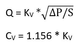
Where,
Q = Flow rate
ΔP = Total pressure drop
S = Specific gravity (1 for water)
CV = Flow coefficient, KV = Flow factor.
Conclusion
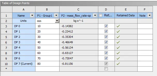
For lower gate lift mass flow rate at the outlet is low at the same time pressure drop is high.
Negative sign indicates that the mass is leaving the system.
Flow Factor and Flow Coefficient increases with increase in mass flow rate.
Parametric study helps in reducing the solving time.