Week 9 - Parametric study on Gate valve.
Parametric study on Gate valve
Aim:To perform a parametric study on the gate valve simulation by setting the opening from 10 % to 80%.
Objectives:
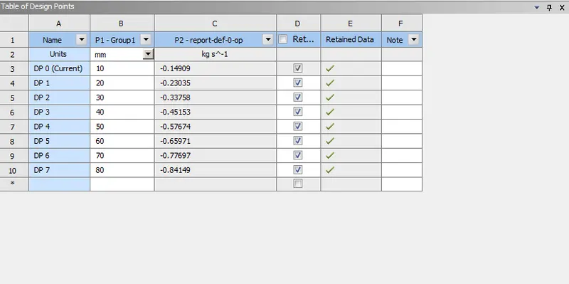
- To obtain the mass flow rates at the outlet for each design point.
- To calculate the flow coefficient and flow factor for each opening and plot the graph.
- Discuss the results of the mass flow rate and flow coefficient.
Introduction:A gate valve also known as a sluice valve, is a valve that opens by lifting a barrier (gate) out of the path of the fluid. Gate valves require very little space along the pipe axis and hardly restrict the flow of fluid when the gate is fully opened. The gate faces can be parallel but are most commonly wedge-shaped (in order to be able to apply pressure on the sealing surface). The work in this project is to perform a parametric study on the above device throughout a simulation in ANSYS Fluent.
Theory:A gate valve, also known as a sluice valve, is a valve that opens by lifting a barrier (gate) out of the path of the fluid.Gate valves are designed for fully open or fully closed service. They are installed in pipelines as isolating valves and should not be used as control or regulating valves.Gate valves require very little space along the pipe axis and hardly restrict the flow of fluid when the gate is fully opened. The gate faces can be parallel but are most commonly wedge-shaped (to be able to apply pressure on the sealing surface).Operation of a gate valve is performed doing an either clockwise to close (CTC) or clockwise to open (CTO) rotating motion of the stem. When operating the valve stem, the gate moves up- or downwards on the threaded part of the stem.
Solving & Modelling:
Creating Geometry:
Importing geometry in SpaceClaim :
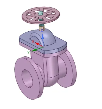
- The bonnet is placed below the handwheel and prevents the splashing of fluid from the upper region.
- Handwheel and spindle that can be used to lift or lower the gate disc.
- The gate disc is attached to the spindle at the bottom.
- The bottom is a casing that covers the gate disc and the water flows through it. Two ports serve as an inlet and outlet for the fluid.
Steps:
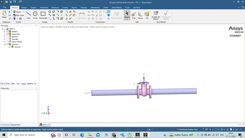
- Hide the "Bottom " Part , so we can claerly see the "Gate Disc".
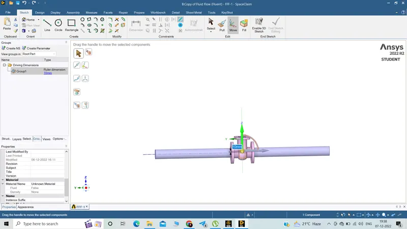
- Then Select "Gate Disc" component and move it in upward direction by "10 mm" lift.
- To analyze the flow and its effects, we must allow the flow, and for that we have given "10 mm" lift to the "Gate Disc".
- Created group for lift parameter shown in above image.
- On the Left Side, in Tree Structure,if we see the group options, we can see created group and the amount of parameter, which has been set 10 mm lift.
- We can simply change the value of parametrs from there directly.
Fluid Volume
- After lifting the "Gate Disc ", move the both faces at the inlet and outlet of the "Bottom" part by amount of 800 mm
- After extension, create Fluid Voume by selecting inlet, outlet and upper edge of the "Bottom" part.
A parametric analysis, also known as a sensitivity analysis, is the study of the influence of different geometric or physical parameters or both on the solution of the problem. Parametric analysis is an important tool for design exploration.
Parametric studies allow us to nominate parameters for evaluation, define the parameter range, specify the design constraints, and analyze the results of each parameter variation.
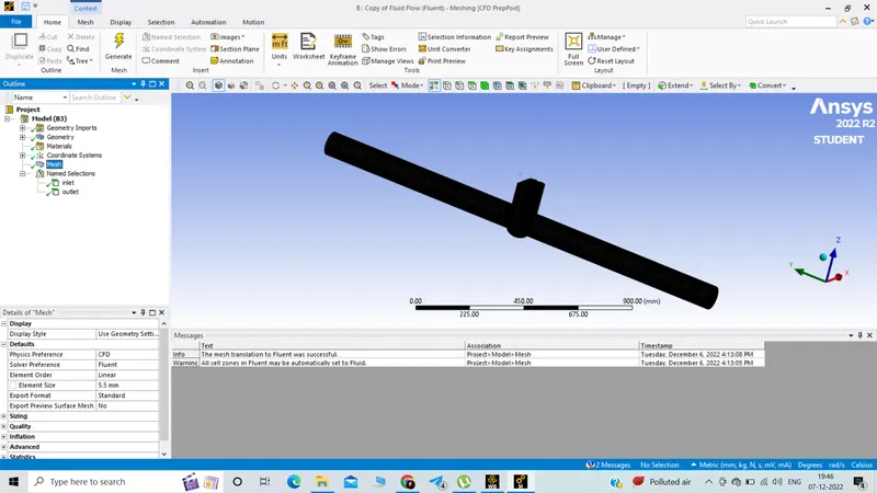
Meshing:
Refined:Element size 5.5 mm
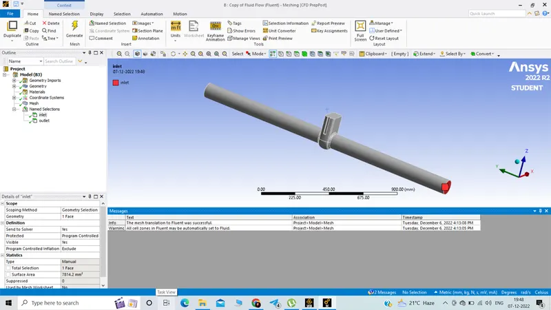
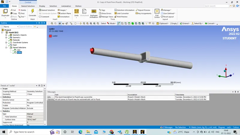
Enabled named selection:
inlet and outlet.
Set up:
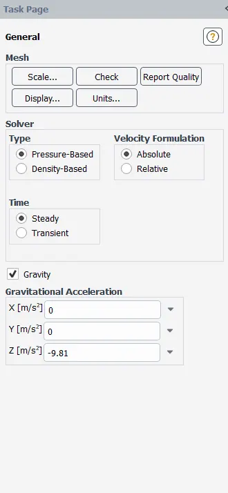
General set up:
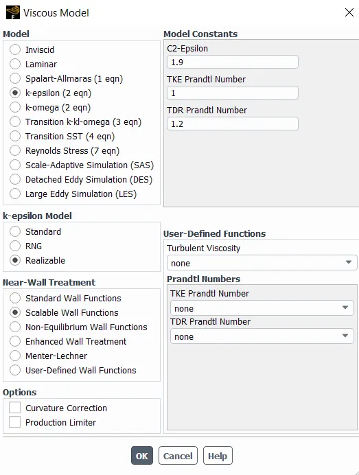
Viscous Model turbulent:
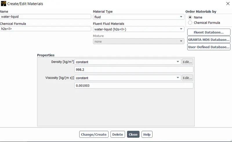
Material fluid:
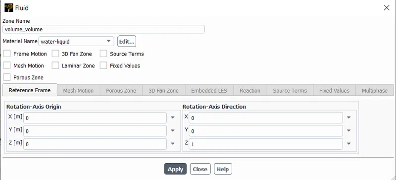
Cell zone conditions:
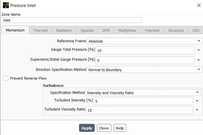
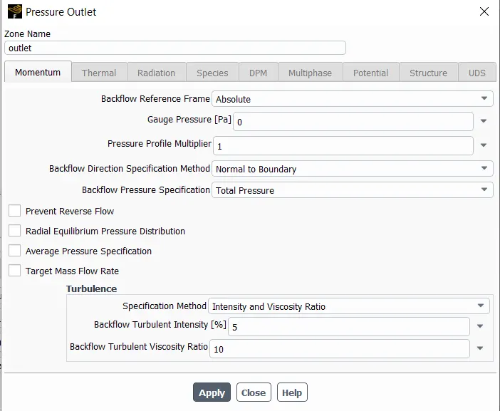
Boundary Conditions:
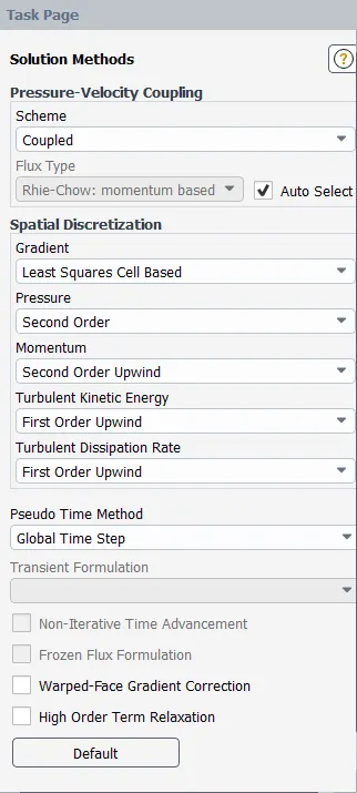
Soliution Method:
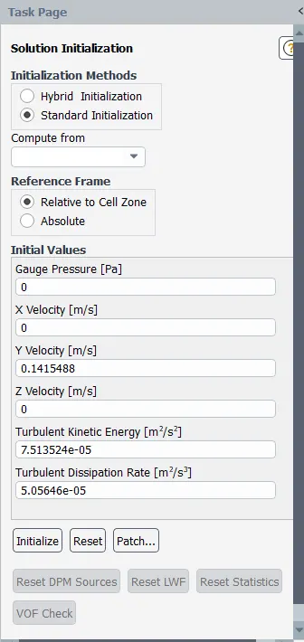
Solution initialization:
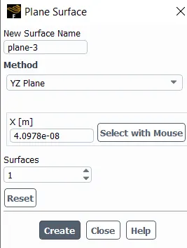
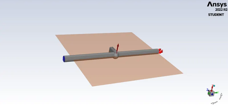
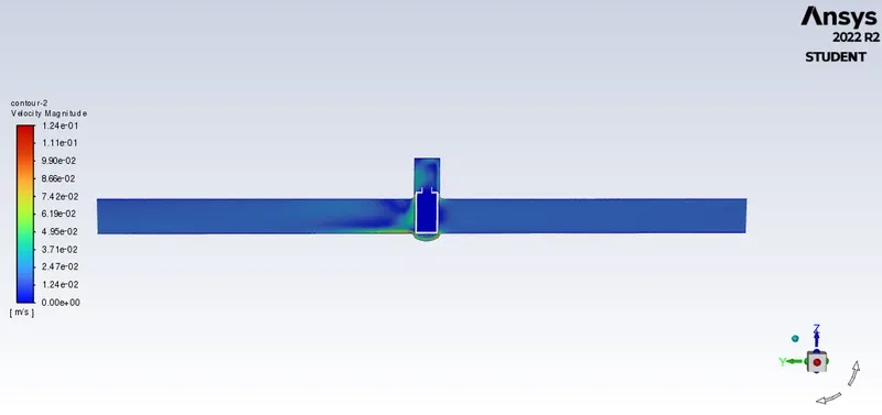
Create plane to see the velocity and pressure contour:
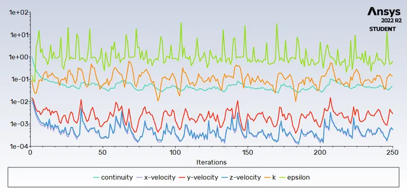
No.of iteration:250
Result:
Mass flow rate in kg/sec foe design points:10 mm to 80 mm:
Gate disc opening : 10 mm
Residuals:
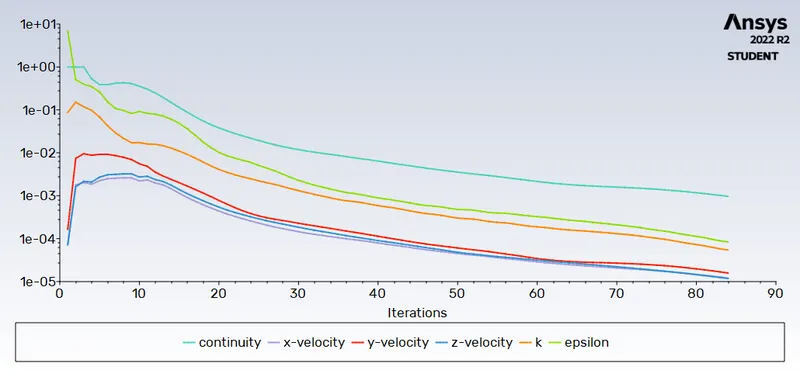
Velocity contour:
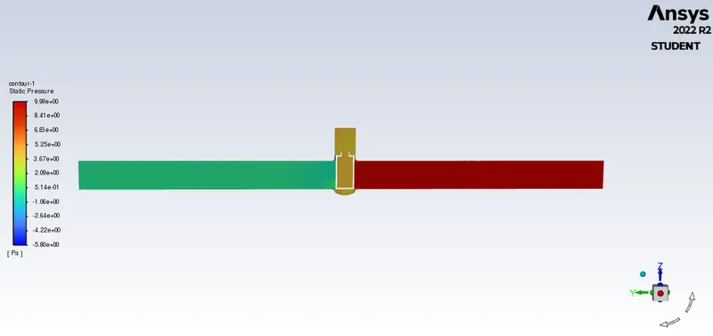
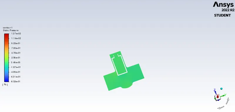
Pressure contour:
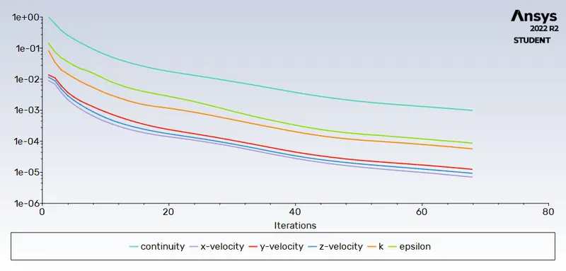
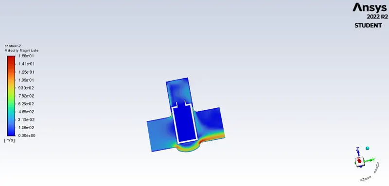
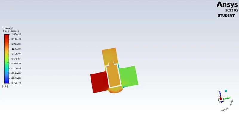
Gate disc opening : 20 mm
Residuals:
Velocity contour:
Pressure contour:
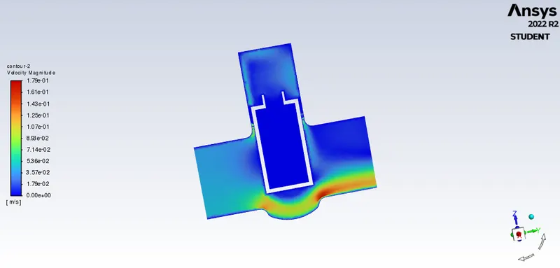
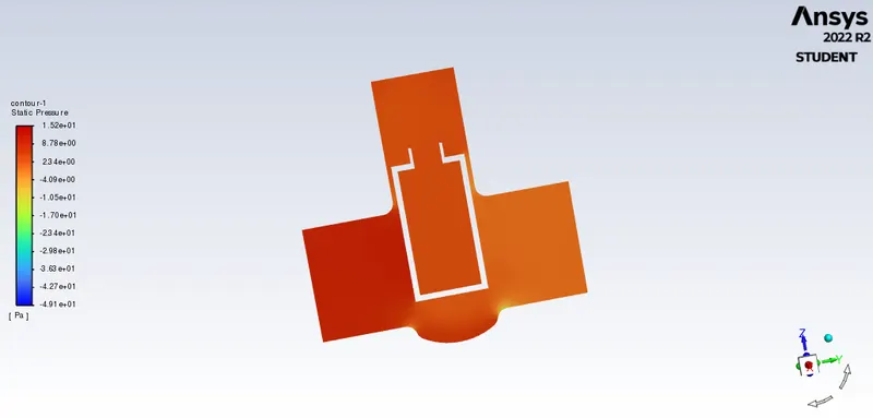
Gate disc opening : 30 mm
Residuals:
Velocity contour:
Pressure contour:
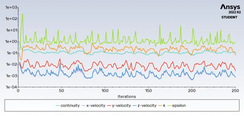
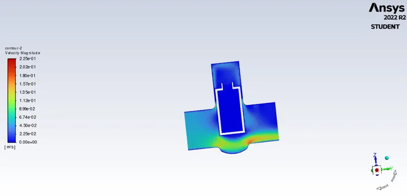
Gate disc opening : 40 mm
Residuals:
Velocity contour:
Pressure contour:
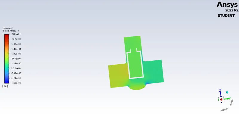
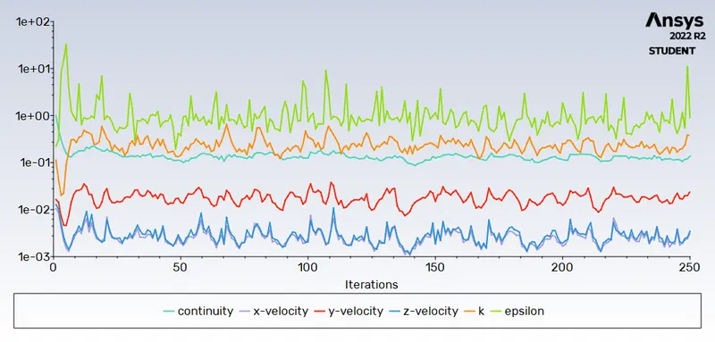
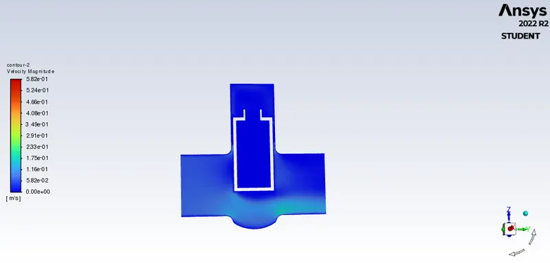
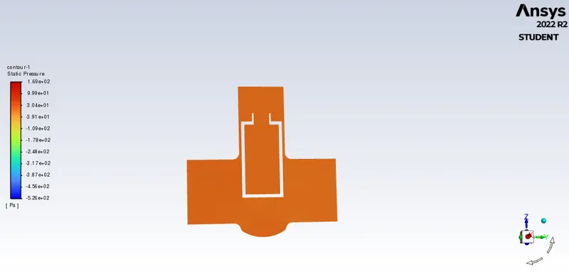
Gate disc opening : 50 mm
Residuals:
Velocity contour:
Pressure contour:
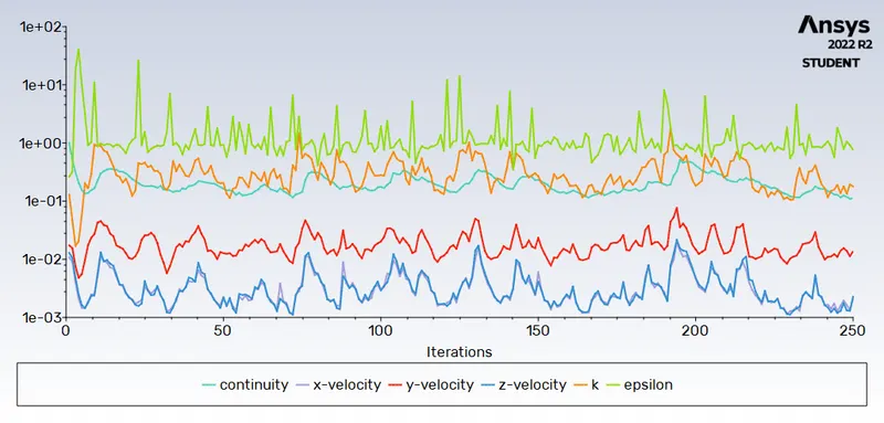
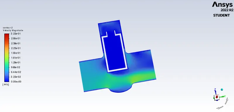
Gate disc opening : 60 mm
Residuals:
Velocity contour:
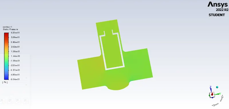
Pressure contour:
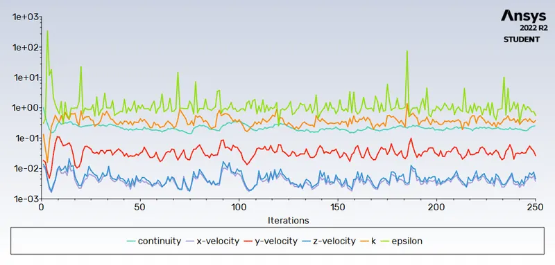
Gate disc opening : 70 mm
Residuals:
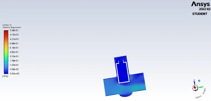
Velocity contour:
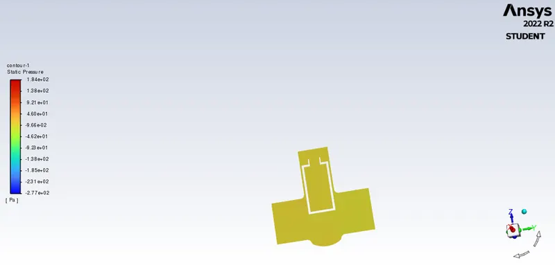
Pressure contour:
Gate disc opening : 80 mm
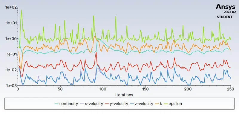
Residuals:
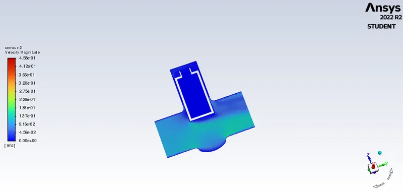
Velocity contour:
Pressure contour:
Flow Coefficient and flow factor:
Flow factor (Kv) is the metric system equivalent of the flow coefficient (Cv).
When flow goes through a valve or any other restricting device it loses some energy. The flow coefficient is a designing factor which relates head drop (Δh) or pressure drop (ΔP) across the valve with the flow rate (Q).
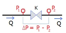
`K=Q/sqrt((DeltaP)/(SG)`
Q: Flow rate
ΔP: Pressure Drop
Sg: Specific gravity (1 for water)
K: Flow coefficient Kv or Cv
Most of valve industry have standardized the flow coefficient (K). It is referenced for water at a specific temperature, and flow rate and drop pressure units. Same model valve has different coefficient for each diameter.
Kv is the flow coefficient in metric units. It is defined as the flow rate in cubic meters per hour [m3/h] of water at a temperature of `16^0 c` with a pressure drop across the valve of 1 bar.
Cv is the flow coefficient in imperial units. It is defined as the flow rate in US Gallons per minute [gpm] of water at a temperature of `60^0 F` with a pressure drop across the valve of 1 psi.
Flow factor:
Kv = Q * √ (SG/ΔP) (units in m3/hr, bar).
Q = Flow in m3/ hr,
SG = Specific Gravity of water ( for water=1).
ΔP = Differential Pressure (bar).
Flow coefficient:
Cv = Q * √ (SG/ΔP) (units in US GPM, psi)
Q = Flow in US GPM,
SG = Specific Gravity,
ΔP = Differential Pressure (psi).
`K_v=0.865*C_v`
- Flow Coefficient and Flow Factor Calculation: (For 10 mm)
Pressure Drop = Total pressure at inlet - Total pressure at outlet.
Therefore, = 10 - 0 = 10 Pa
We need the pressure in terms of psi, conversion form Pascal to psi is 1bar=10^5 pa
So, 1 Pa = 10^-5 bar
10 pa=0.0001 bar
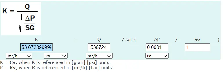
Q = 0.14909 kg/s=0.536724 m3/h
[1 kg/s = 3.6 m3/h]
Specific Gravity of water = 1
Flow coefficient:Kv = Q * √ (SG/ΔP)=0.536724*√ (1/0.0001)=53.67
Flow factor:Cv=Kv/0.865=62.05
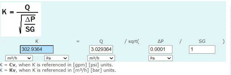
Result from online calculator is verfied.
- Flow Coefficient and Flow Factor Calculation: (For 20 mm)
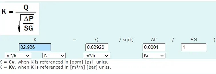
- Q = 0.23035 kg/s=0.82926 m3/h
Flow coefficient:Kv=82.93
Flow factor:Cv=Kv/0.865=95.87
- Flow Coefficient and Flow Factor Calculation: (For 30 mm)
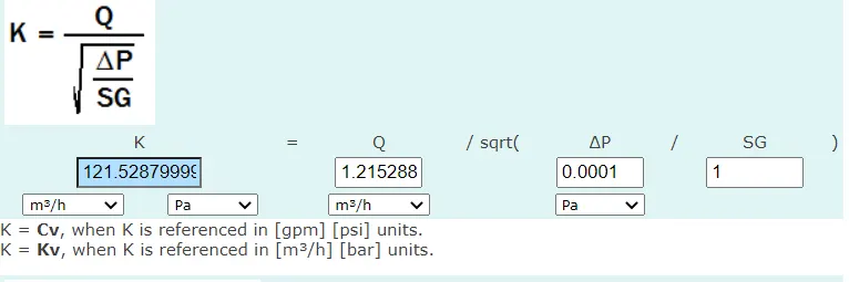
- Q =.33758 kg/s=1.215288 m3/h
Flow coefficient:Kv=121.53
Flow factor:Cv=Kv/0.865=140.49
- Flow Coefficient and Flow Factor Calculation: (For 40 mm)
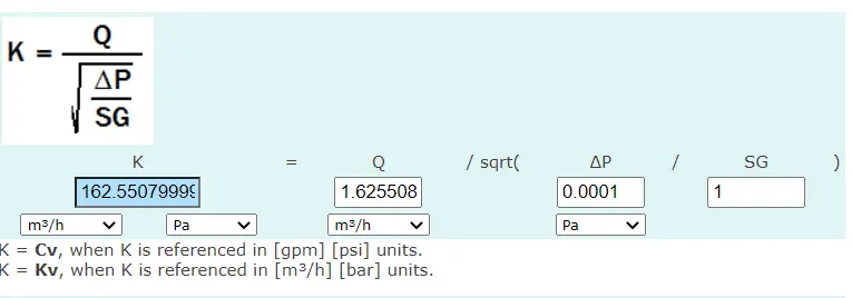
- Q = 0.45153 kg/s=1.625508 m3/h
Flow coefficient:Kv=162.55
Flow factor:Cv=Kv/0.865=187.92
- Flow Coefficient and Flow Factor Calculation: (For 50 mm)
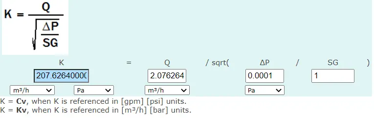
- Q = 0.57674 kg/s=2.076264 m3/h
Flow coefficient:Kv=207.63
Flow factor:Cv=Kv/0.865=240.03
- Flow Coefficient and Flow Factor Calculation: (For 60 mm)
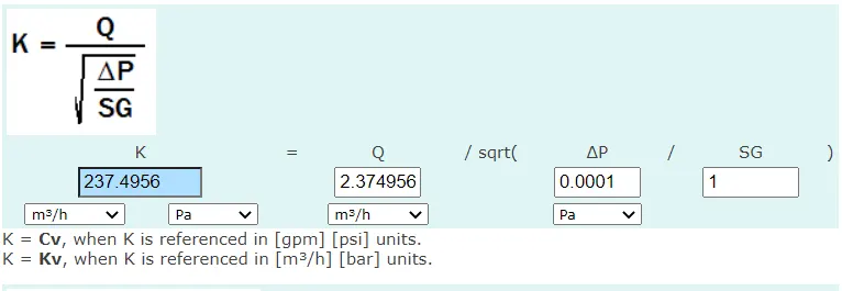
- Q =0.65971 kg/s=2.374956 m3/h
Flow coefficient:Kv=237.49
Flow factor:Cv=Kv/0.865=274.55
- Flow Coefficient and Flow Factor Calculation: (For 70 mm)
- Q =0.77697 kg/s=2.797092m3/h
Flow coefficient:Kv=279.71
Flow factor:Cv=Kv/0.865=323.36
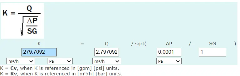
- Flow Coefficient and Flow Factor Calculation: (For 80 mm)
- Q =0.84149 kg/s=3.029364 m3/h
Flow coefficient:Kv=302.94
Flow factor:Cv=Kv/0.865=350.22
| Opening setting | pr at inlet | pr at outlet | pr drop | mass flow rate | Kv | Cv |
|
10 mm |
10 pa | 0 pa | 10pa=0.0001 bar | 0.536724 m3/h | 53.67 | 62.05 |
|
20 mm |
10 pa | 0 pa | 10pa=0.0001 bar | 0.82926 m3/h | 82.93 | 95.87 |
|
30 mm |
10 pa | 0 pa | 10pa=0.0001 bar | 1.215288 m3/h | 121.53 | 140.49 |
|
40 mm |
10 pa | 0 pa | 10pa=0.0001 bar | 1.625508 m3/h | 162.55 | 187.92 |
|
50 mm |
10 pa | 0 pa | 10pa=0.0001 bar | 2.076264 m3/h | 207.63 | 240.03 |
|
60 mm |
10 pa | 0 pa | 10pa=0.0001 bar | 2.374956 m3/h | 237.49 | 274.55 |
|
70 mm |
10 pa | 0 pa | 10pa=0.0001 bar | 2.797092m3/h | 279.71 | 323.36 |
| 80 mm | 10 pa | 0 pa | 10pa=0.0001 bar | 3.029364 m3/h | 302.94 |
350.22 |
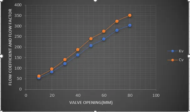
Cv and Kv with respect to valve opening
- From the above Tabular Data and Graphs, we can observe that as the opening of the Gate Valve or Lift of the Gate Disc increases the mass flow rate increases.
- With increase in mass flow rate, there is an increment in Flow Coefficient and flow factor.
Conclusion:With very little marginal work a completed model can be parameterized to simulate scenarios limited only by computational time and resources. It can be concluded that the mass flow rate, flow coefficient, and flow factor varies linearly with gate disc opening.