Week 9 - Parametric study on Gate valve.
Aim:
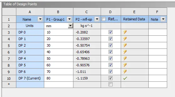
To perform a parametric study on the gate valve simulation by setting the opening from 10 % to 80%.
Objective:
Obtain the mass flow rates at the outlet for each design point.
Calculate the flow coefficient and flow factor for each opening and plot the graph.
Discuss the results of the mass flow rate and flow coefficient.
Gate valve:
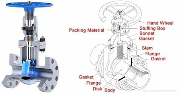
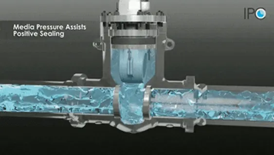
A gate valve is the most common valve for water supply systems. It represents a linear-motion isolation valve and has a function to stop or allow the flow. Gate valves got their name from the closure element sliding into the flow stream to provide shutoff and, therefore, acting like a gate. Gate valves are used to isolate specific areas of the water supply network during maintenance, repair works, new installations, as well as to reroute water flow throughout the pipeline.
Based on construction, gate valves for water supply systems can generally be divided into the following types:
- By wedge: parallel gate valves and wedge gate valves
- By seat: metal seat or resilient seated gate valves
- By stem: with rising or non-rising stem.
Challenge procedure:
In this challenge we have to do five steps process Geometry, Meshing, Set-up, Solution, Result. We have to complete these five steps. In this challenge we have to do 8 cases for gave valve disc lift position 10mm to 80mm.
Step 1: Geometry
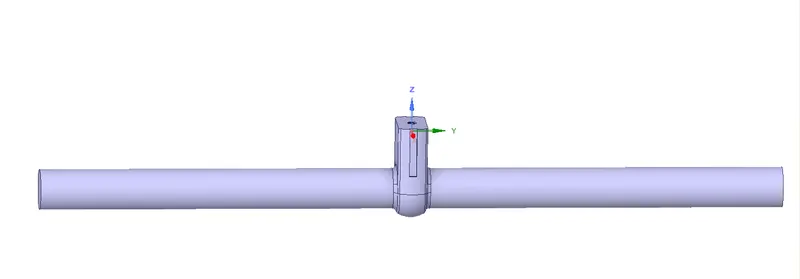
First open the fluent workbench and then right click open the geometry space claim. Go to pull > 800 mm right and left > ok. Go to prepare option > volume extract > edge selection > click green tick > ok. We can use move tool > select disc > create parameter > 10mm > ok. Suppress for physics we have only fluid volume.
Step 2: Meshing
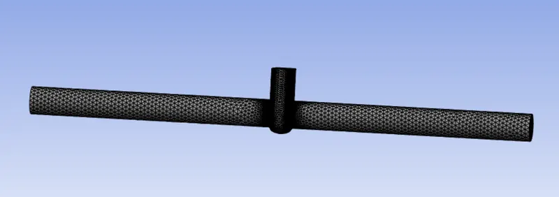
Once we complete the geometry process next step is meshing process right click open the mesh option > generate mesh. In this challenge we have to use default CFD tetra mesh element size is 92 mm. Go to face selection option > select face > create named selection option > inlet > create named selection option > outlet.
Step 3: Set-up
Right click and open the set-up option we should select the Type: Pressure based, Velocity Formulation: Absolute, Time: Steady, Gravity on in Z axis input -9.81 m/s^2.
Under the Physics tab, go to viscous and select k-epsilon > RNG > Swirl dominating flow as well. Go to materials option select water liquid. In cell zone condition we have to delete the air material.
Next go to boundary condition > inlet > pressure inlet 20 pa > outlet > pressure outlet.
Solution > definition > surface > mass flow rate > name (mfl) > outlet > print to console > create output parameters > ok. Initialize > Run calculation 350 iteration.
Step 4: Solution
In this challenge some processes are already done by set-up process. So, we have to move next result option.
Step 5: Result
In this challenge the final step is result process go to location > create plane > select velocity > location > create vector > select velocity. Take a screen shot. Go to animation option select animation and save animation video for Case 2 to 8 we can change the disc lift position in the parameter set itself as 20, 30, up to 80 mm and right click update selected design points will update the results. Later in post processing we can create contours, streamlines.
Case 1 disc 10 mm velocity, velocity vector streamline contour images and gif:
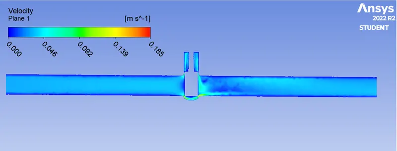
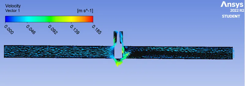
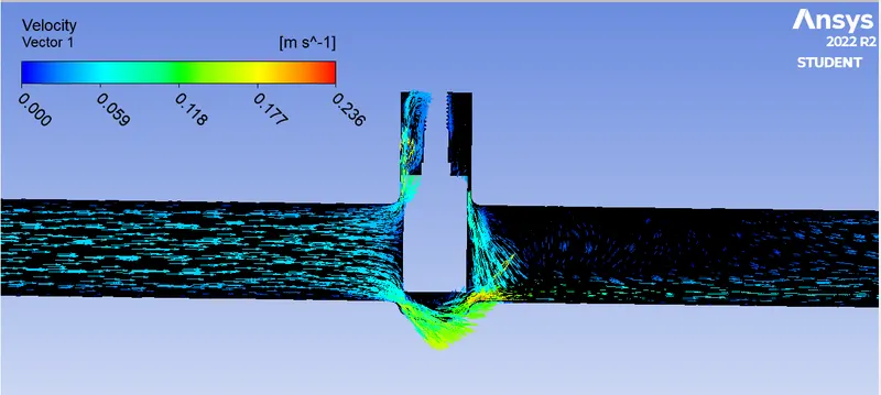
Case 2 disc 20 mm velocity, velocity vector streamline contour images and gif:
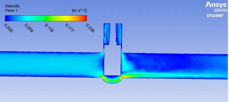
Case 3 disc 30 mm velocity, velocity vector streamline contour images and gif:
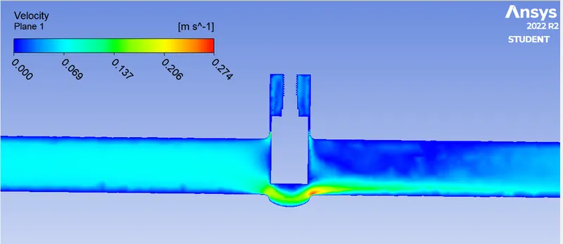
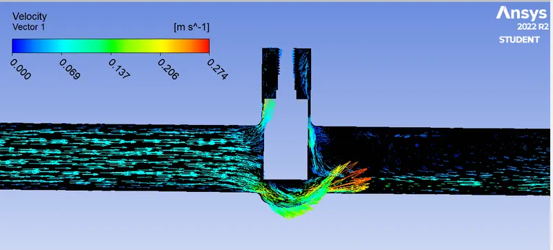
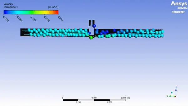
Case 4 disc 40 mm velocity, velocity vector streamline contour images and gif:
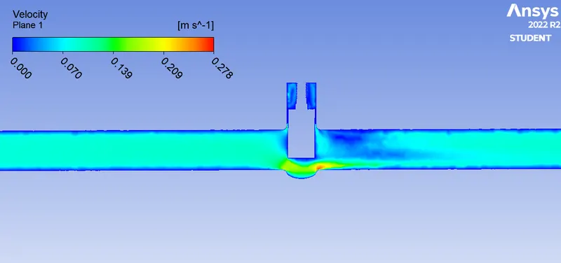
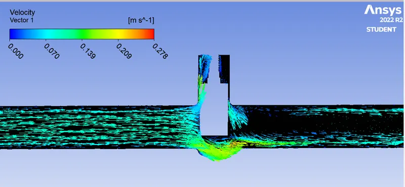
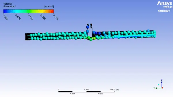
Case 5 disc 50 mm velocity, velocity vector streamline contour images and gif:
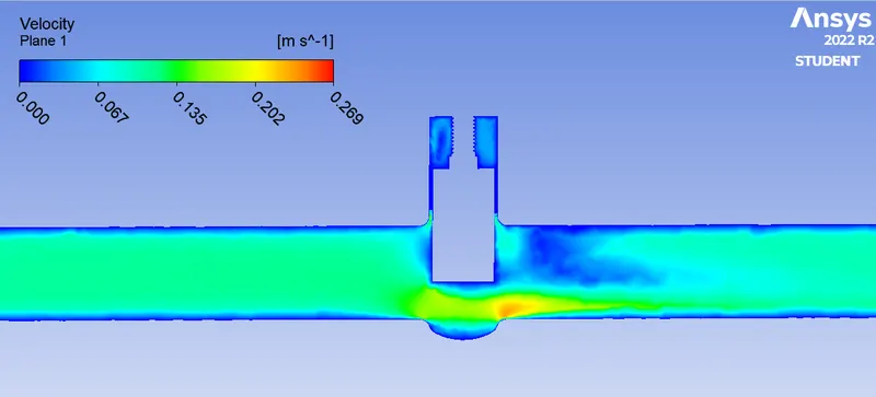
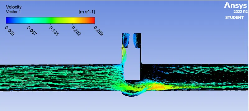
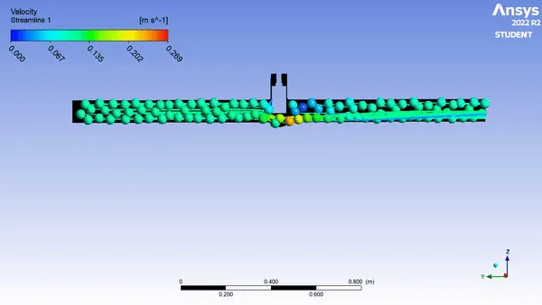
Case 6 disc 60 mm velocity, velocity vector streamline contour images and gif:
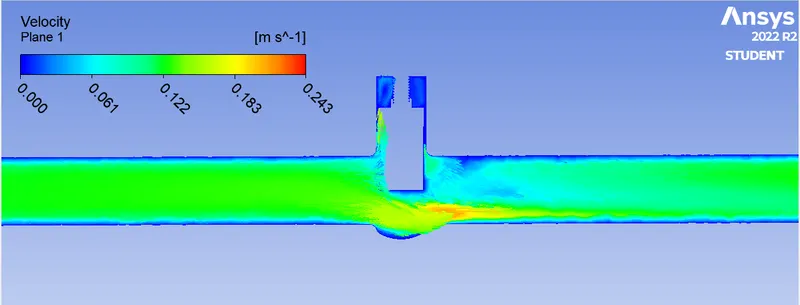
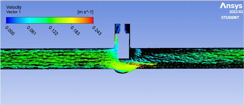
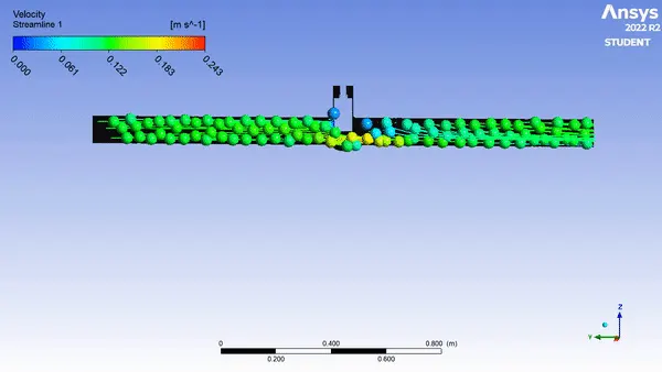
Case 7 disc 70 mm velocity, velocity vector streamline contour images and gif:
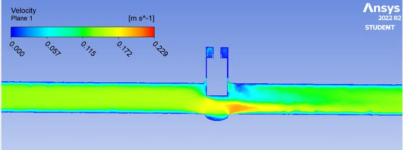
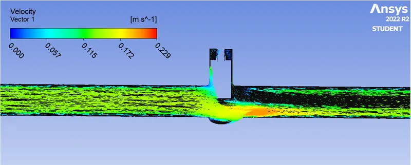
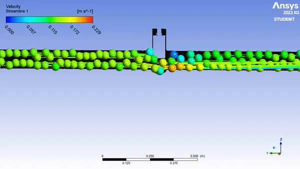
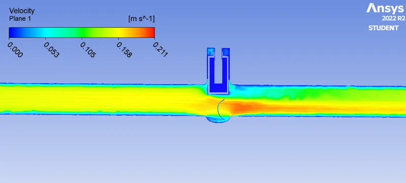
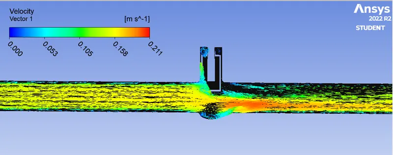
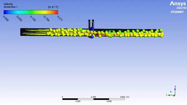
Case 8 disc 80 mm velocity, velocity vector streamline contour images and gif:
Conclusion:
Finally, in this challenge we had conclude the values of mass flow rate, flow factor, and flow coefficient.
case Disc Lift Inlet Pressure Mass Flow rate Flow Coefficient Flow Factor
position(mm) Pressure(mm) mfl Drop Kg/s CV KV
1 10 20 0.208 0.74 0.048 0.039
2 20 20 0.336 1.21 0.078 0.066
3 30 20 0.507 1.81 0.119 0.104
4 40 20 0.654 2.37 0.162 0.14
5 50 20 0.789 2.82 0.204 0.176
6 60 20 0.905 3.24 0.249 0.218
7 70 20 1.011 3.66 0.303 0.262
8 80 20 1.115 4.01 0.366 0.317
Inferences:
In this challenge finally we conclude, when the disc position opens fully the mass flow rate also increase. Since the max velocity occurs at the disc exit radius zone (from velocity contour) that area is prone to surface abrasion in long term, so the material used plays a major role in determining the life of the valve. Say, we can use gun metal valve in place of cast iron valves for high pressure inlet conditions.
Reference:
https://www.sciencedirect.com/topics/engineering/gate-valve
https://whatispiping.com/gate-valves-gate-valve-types/