Week 9 - Parametric study on Gate valve.
Parametric study on Gate valve.:
Theory:
Gate valves work by inserting a rectangular gate or wedge into the path of a flowing fluid. They are operated by a threaded stem
which connects the actuator (generally a hand wheel or motor) to the stem of the gate. If the valve has a rising stem its position can be seen just by looking at the position of the stem. A gate valve is used to control the fluid flow through lifting and descending the gate. A gate distinct feature is to provide an unobstructed passageway, which includes minimal pressure loss over the valve. When the gate is fully opened there is no restriction to the flow hence the pressure drop is low comparatively. Generally, the gate valve are fully closed or fully open as a partially opened valve may experience vibration which may lead to excessive wear. A gate valve's main component is the body, seat, gate, stem, bonnet, and actuator. the primary mechanism is straight forward where the handwheel is rotated to move the gate up and down via threads. they require more than a 360-degree turn to fully open the valve. Gate valves tend to be slightly cheaper than ball valves of the same size and quality. They are slower in actuation than quarter-turn valves and are for applications where valve operation is infrequent, such as isolating valves. Gate valves should be used either fully open or fully closed, not to regulate flow. Automated gate valves exist with either an electric or pneumatic actuator, but a manual gate valve is cost-effective since they have infrequent usage. Gate valves are widely used for all types of applications and are suitable for both above-ground and underground installation. They are suitable for most fluids including steam, water, oil, and gas, etc.
Ansys setup:
Geometry:
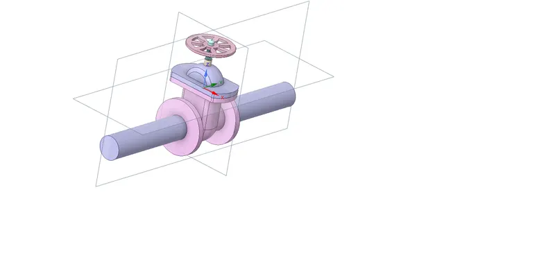
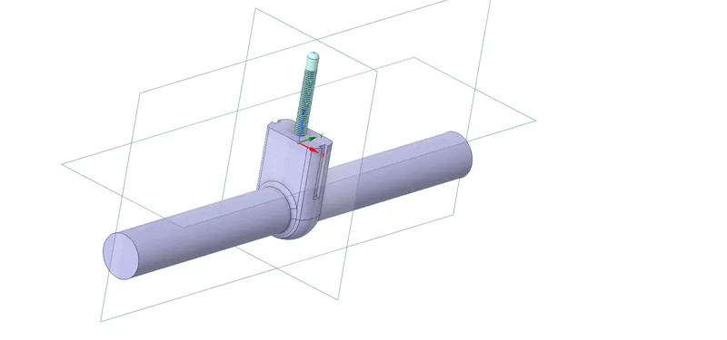
Extract the fluid volume
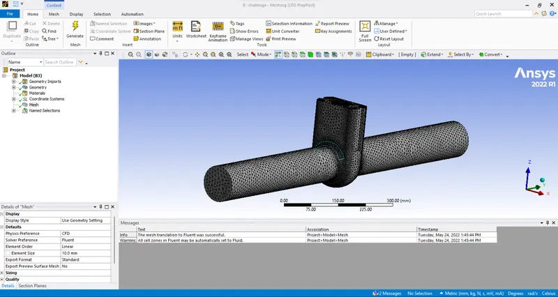
Meshing :
Mesh the file with reqired parameters
Fluent setup:
Assign the all required attributes like
solver types : pressure based ;
mterial : water;
model : K - epsilon ;
boundary conditions:
Inlet: inlet pressure
outlet: outlet pressure:
solution method: coupled
run the simulations
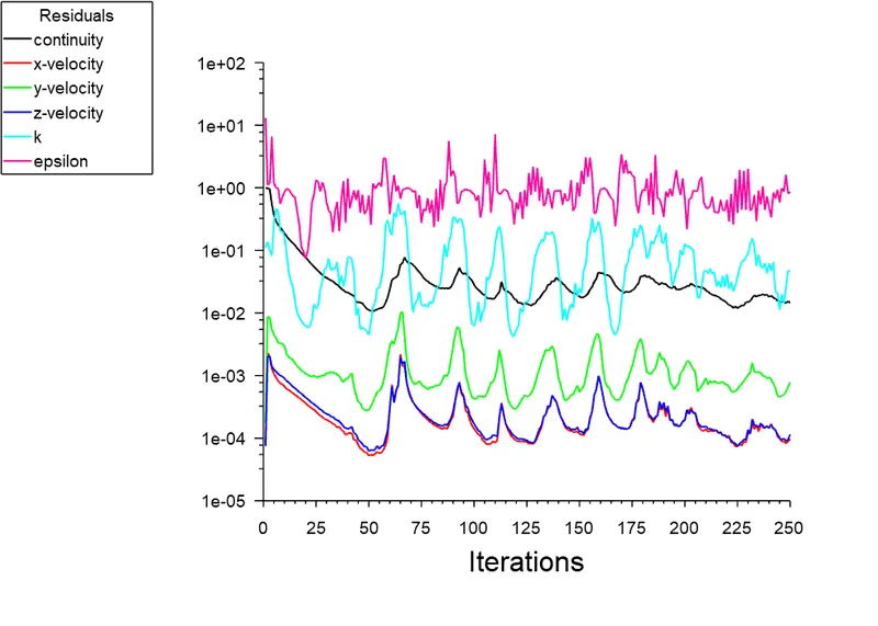
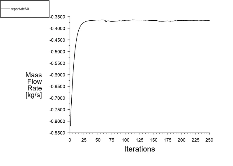
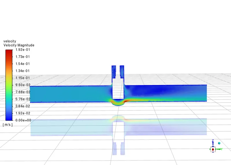
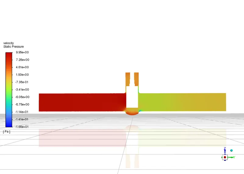
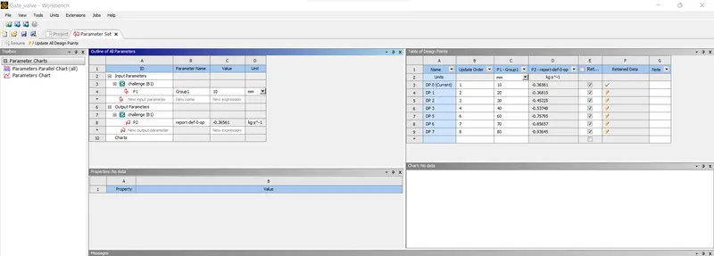
mass flow rates at the outlet for each design point.
The flow coefficient (Cv) is also additionally referred to as the valve flow coefficient. It is an imperial measurement system of unit and is defined as the flow of water through a valve at 60°F in US gallons per minute (GPM) at a pressure drop of 1 pound/square inch (lb/in²).
Flow factor (Kv) is the metric system equivalent of the flow coefficient (Cv). Also referred to as International System of units (abbreviated as SI system). It is defined as the flow of water in cubic meters per hour (m³/hr) at a pressure drop of one bar with temperature ranging from 5 to 30 degree C.
Cv = 1.156 Kv OR Kv = 0.864 Cv.
Unit conversions from Imperial to Metric (vice versa):
1 US GPM = 0.227125 m3/hr. 1 m3/hr = 4.402868 US GPM
1 psi = 0.06894757 bar. 1 bar = 14.503773773 psi.
60 deg F = 15.5 deg C.
| valve displacement | mass flow rate | flow factor | flow coefficient | valve displacement | mass flow rate | flow factor |
| 10 | 0.3656093 | 107.615 | 124.411 | 173.218 | 218.266 | 263.314 |
| 20 | 0.3681479 | 108.395 | 125.312 | 169.509 | 211.906 | 254.302 |
| 30 | 0.4522533 | 133.126 | 153.903 | 205.466 | 255.905 | 306.343 |
| 40 | 0.5374772 | 158.192 | 182.881 | 241.977 | 300.607 | 359.236 |
| 60 | 0.7579529 | 223.028 | 257.836 | 339.351 | 420.928 | 502.506 |
| 70 | 0.8565658 | 252.105 | 291.45 | 382.503 | 474.062 | 565.622 |
| 80 | 0.9364536 | 275.611 | 318.625 | 416.43 | 515.485 | 614.54 |
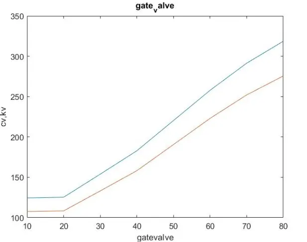
blue is cv and red is kv.
conclusions:
Using the parametric study method saves a lot of time in the simulations which require performing the same operations for different settings multiple times.
In the parametric study of the gate valve, it was found that as the valve stopping is lifted gradually, the mass flow rate of the
fluid, and hence the flow factor and flow coefficient increase.