Week 9 - Parametric study on Gate valve.
Aim: To study the flow through the gate valve for different opening position positions and also studying flow coefficient and flow factors for various mass flow rate at the outlet.
Theory:
- For measuring the valve capcity of control valves, the coefficient of Cv or its Metric equivalent Kv is adopted.
- The Valve flow coefficient is a measurement that pipefitters engineers and manufacturers use to find the right sized valves for the amount of fluid that will pass through them.
- Put simply the Cv helps workers choose the right size valve so all fluids can pass through at the desired pressure.
Importance of Cv:
- If the hole is too small , you can get a pressure drop that will make your liquid drop below its vapour pressure. if your liquid drops below its vapour pressure there will get implosions that damage the valve trims, cause of wear which is also known as cavitation. undersized Cv's will lead to higher pressure drop across the valve. This can lead to cavitation or flashing.
- Larger or oversized valve will lead to increased cost, size and weight of larger valve size are major disadvantages.
Simulation Setup process:
- Import the gate valve model in space claim >> suppress all components for physics.
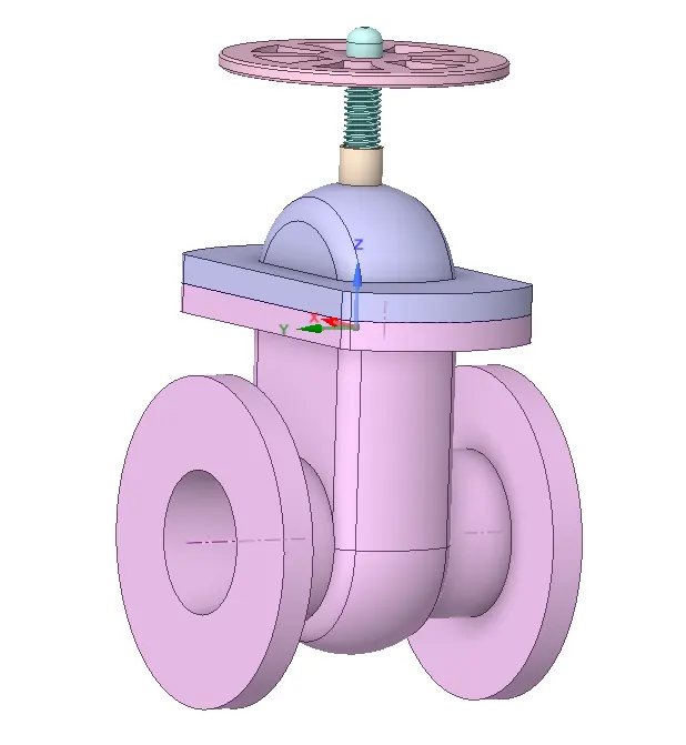
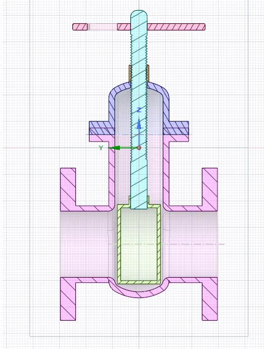
- Make only the gate disc visible >> Select Design >> Move the component for 10mm >> from the left side flow tree select the group option >> Create new parameter >> ok.
- Now the gate disc lift is being parameterized.
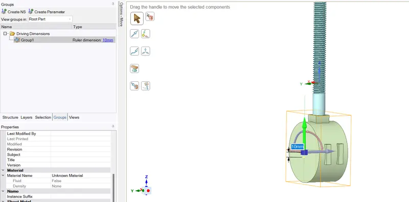
- Prepare >> Volume extract >> Select the edges >> click ok
- Check in the section view whether the extracted volume is confined to the gate disc lift, if not then Click on volume from the flow tree and right click volume and select Update volume under the context.
- Then select pull tool >> select the Inlet face of the valve >> pull to 800mm. similarly do the same procedure for Outlet face.
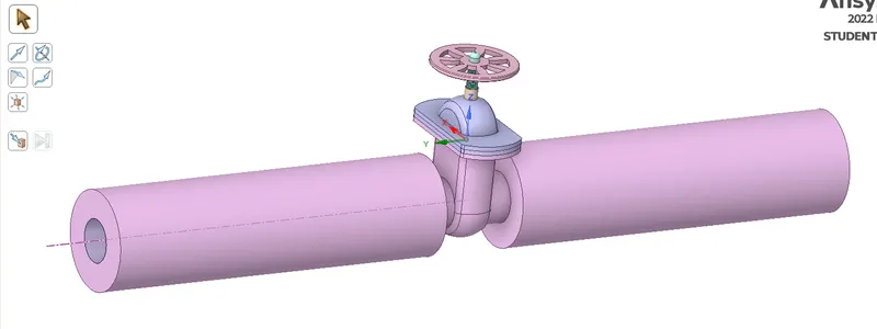
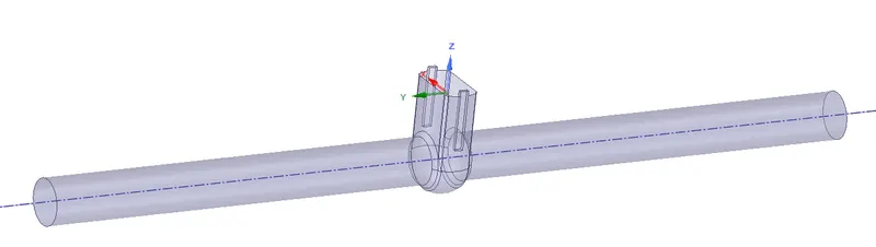
- Check the extracted volume, whether the volume has occupied the entire geometry or not.
- Open the mesh >> change the element size to 0.006m >> Generate Mesh >> Update the Mesh.
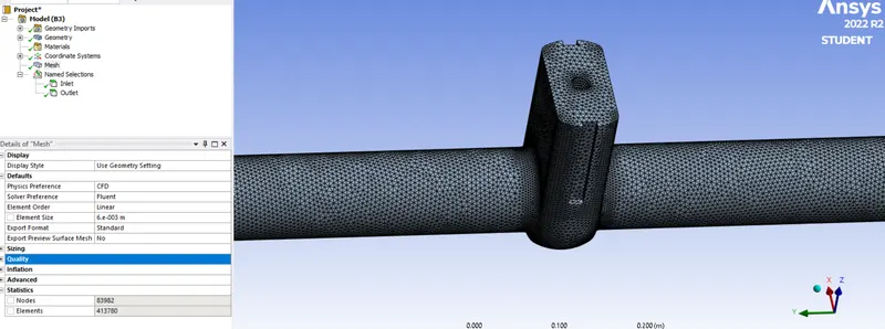

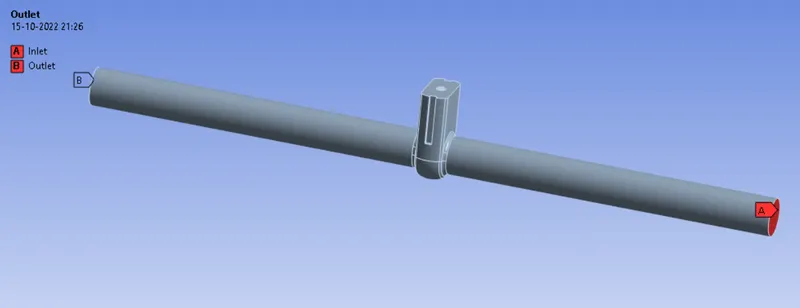
- Open Ansys Setup >> Steady State simulation >> Gravity ON >> check the geometry and mention Z= -9.81m/s^2.
- Create Material >> fluent database >> copy water liquid.
- Cell Zone >> Volume >> changes the material to water >> open material >> delete Air. So as to avoid any confusion.
- Boundary >> Inlet >> Pressure-inlet >>10pa.; Outlet >> pressure-outlet >> 0pa.
- Initialize >> standard >> option >> Inlet >> check the velocity, and calculate the Reynolds no. to check whether the flow is turbulent or not.
- Since the flow is turbulent hence choose the viscous turbulent model >> K-epsilon >> Realizable >> Scalable wall function.
- Create the Definition >> Flux >> mass flow rate >> outlet >> Click output parameter; Area Weighted Average >> Pressure >> Total Pressure >> Outlet >> Click output parameter.
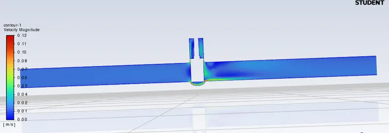
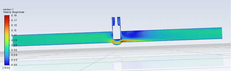
- Create mid plane through the longitudinal axis of the valve >> Create Contour >> Velocity >> Choose the created plane.
- Create >> Solution Animation >> choose the contour >> ok
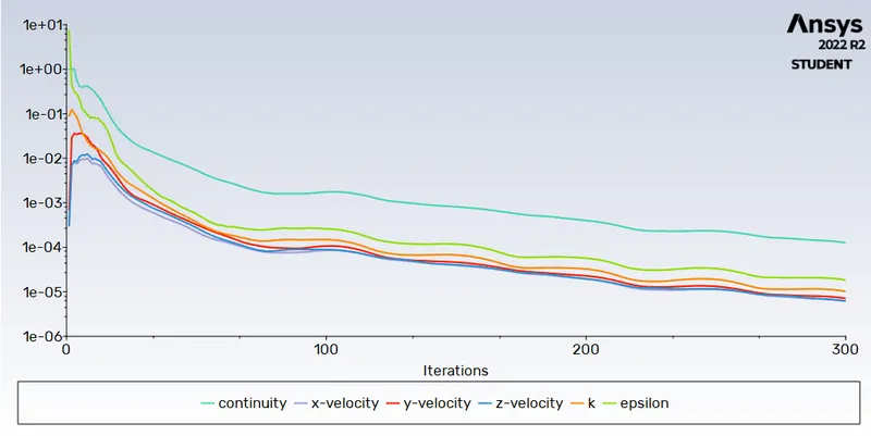
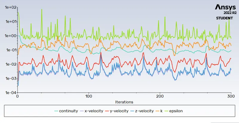
- Run the Simulation for 300 iterations.
- In the main window below result there is parameter row click on it to view parameter window. Within the parameter window add different design points and mention the gate lift value. Update all design point will provide you the corresponding output parameter for different design point.
- Right Clicking each design point >> set as current, will help you to change the gate lift value without entering in geometry window. This helps to run the simulation at ease.
Case-1: Lift of 10mm
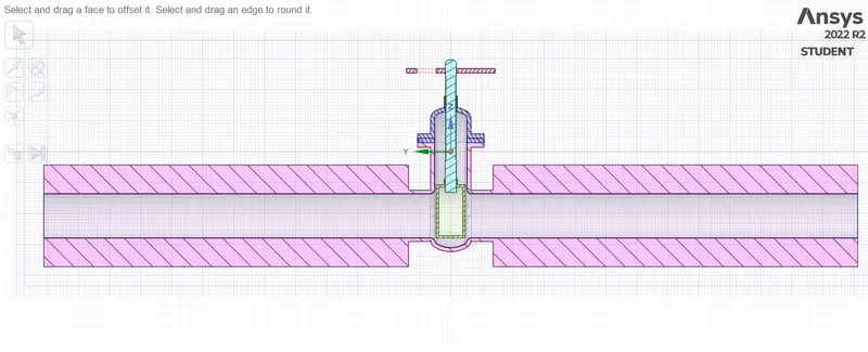
- Sectional View:
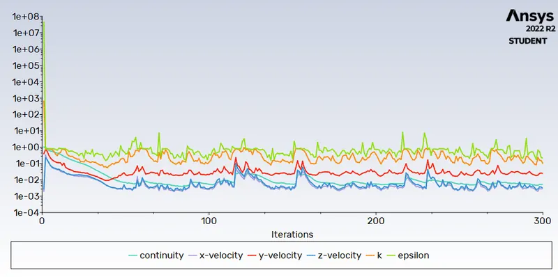
- Residual:
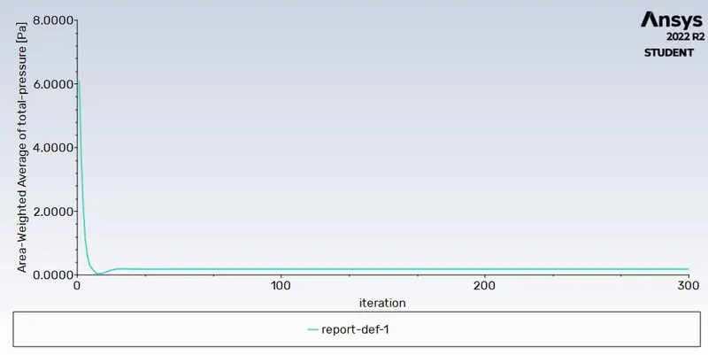
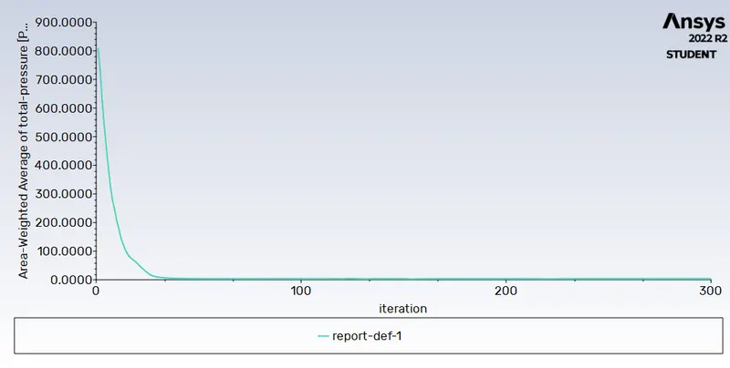
- Area Weighted Average of Outlet Pressure:
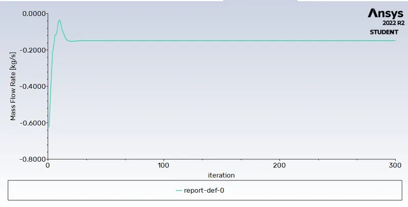
- Mass Flow Rate at Outlet:
- Velocity Contour:
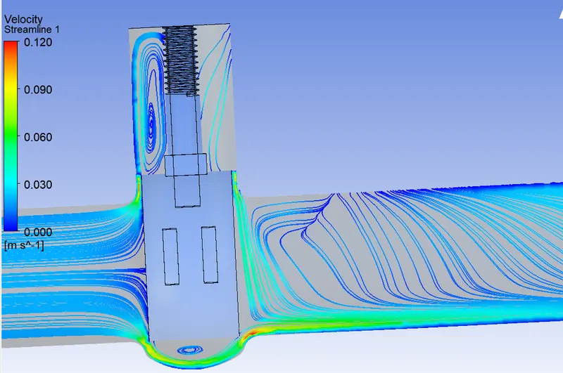
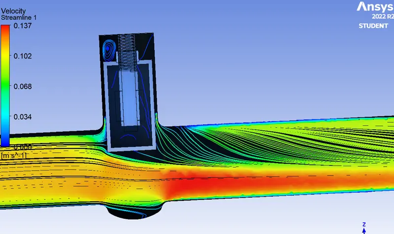
- Velocity Streamline:
Case-2: Lift of 20mm
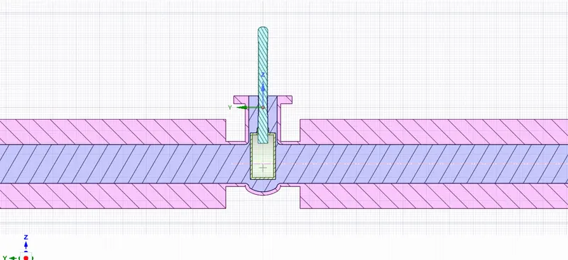
- Sectional View:
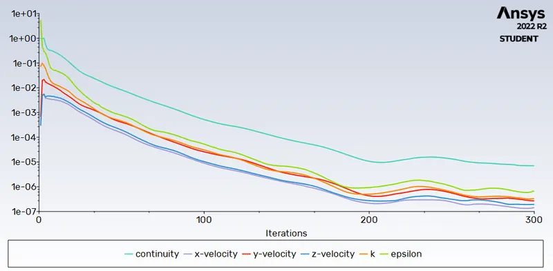
- Residual:
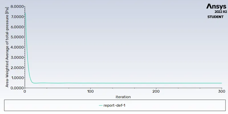
- Area Weighted Average of Outlet Pressure:
- Mass Flow Rate at Outlet:
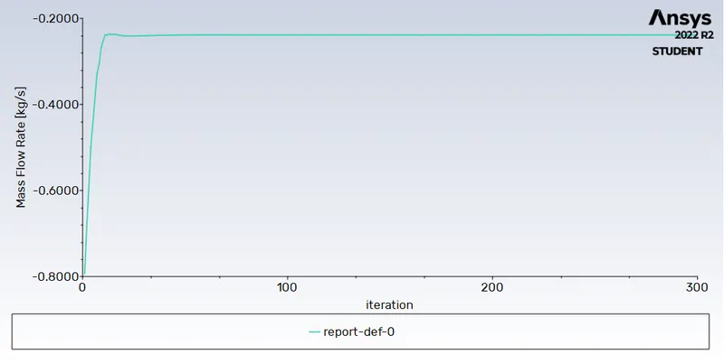
- Velocity Contour:
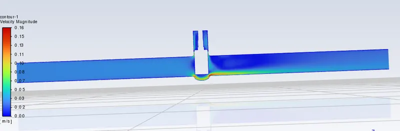
- Velocity Streamline:
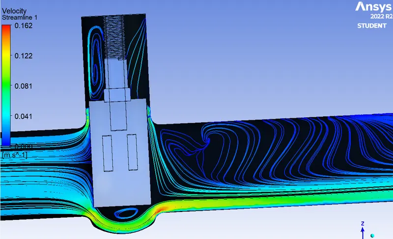
Case-3: Lift of 40mm
- Sectional View:
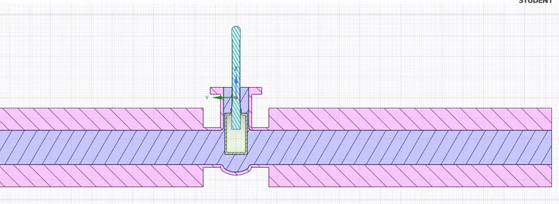
- Residual:
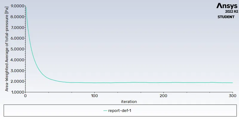
- Area Weighted Average of Outlet Pressure:
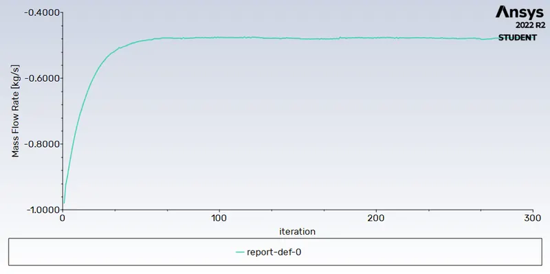
- Mass Flow Rate at Outlet:
- Velocity Contour:
- Velocity Streamline:
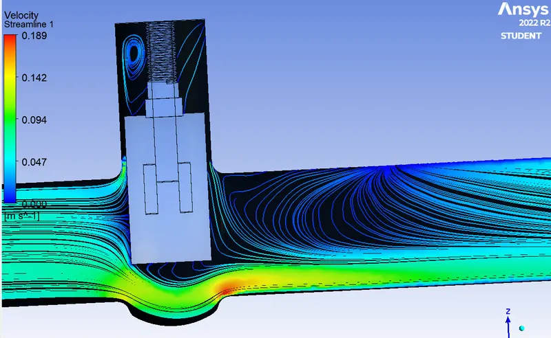
Case-4: Lift of 60mm
- Sectional View:
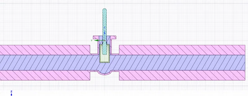
- Residual:
- Area Weighted Average of Outlet Pressure:
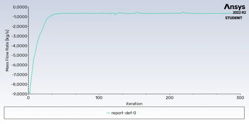
- Mass Flow Rate at Outlet:
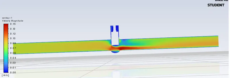
- Velocity Contour:
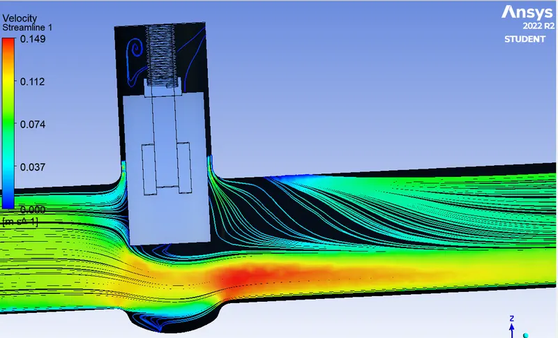
- Velocity Streamline:
Case-5: Lift of 80mm
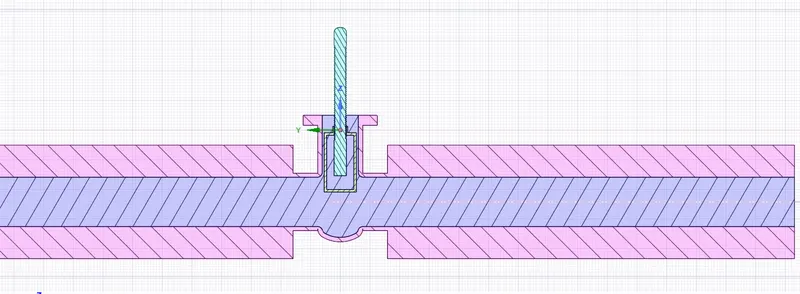
- Sectional View:
- Residual:
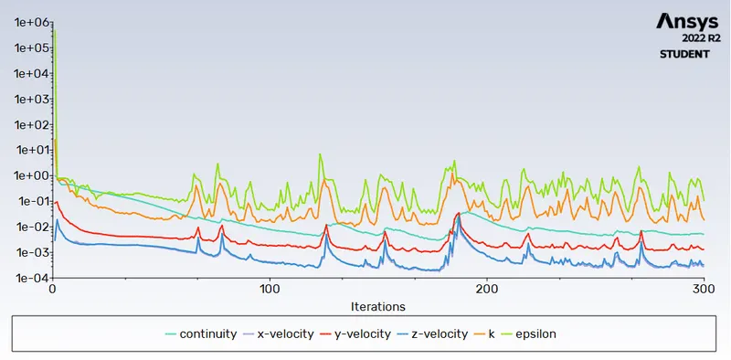
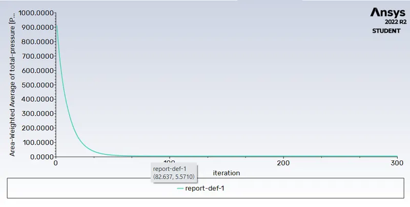
- Area Weighted Average of Outlet Pressure:
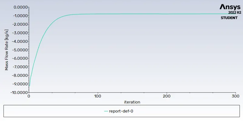
- Mass Flow Rate at Outlet:
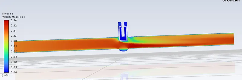
- Velocity Contour:
- Velocity Streamline:
Valve Coefficient (Cv): Cv is the imperial unit and is defined as the no. of US Gallons Per Minute of water at 60*F that will flow through a valve at specific opening with a pressure drop of 1psi across the valve.
`Cv=Q*sqrt((SG)/(Delta P)`
Where, Q: Discharge in US GPM
SG: Specific Gravity at 60*F
`Delta P`: Pressure drop in PSI
Flow Factor (Kv): Kv is Metric unit and is defined as the amount of water that will flow in m3/hr with a temperature range of 5 to 30*C and pressure drop of 1bar.
`Kv=Q*sqrt((SG)/(Delta P)`
Where, Q: Discharge in m3/hr
SG: Specific Gravity at 15.6*C
`Delta P`: Pressure drop in Bar
Relationship between Cv & Kv :
Cv =1.156*Kv or Kv=0.864*Cv
Unit Conversion:
1m3/hr = 4.402882 US GPM
1bar = 14.503774 psi
Calculation:
Calculating for first design point i.e. lift of 10mm
Since working fluid is water so,
Density(`rho`) = 1000 Kg/m3
Discharge (m3/hr) = Mass Flow (Kg/s) * 3600 / Density (Kg/m3)
= (0.14894 * 3600) / 1000
= 0.53618
Flow Factor (Kv) = `Q*sqrt((SG)/(Delta P)`
= `0.53618*sqrt((1)/(9.81693*10^-5)`
= 54.116
Flow Coefficient (Cv) = 1.156 * Kv
= 62.558
Similarly, Calculate for other Design point as well
Result:
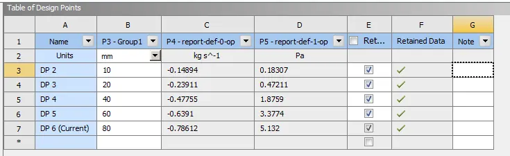
- In Ansys mass coming in is positive & mass leaving is Negative , hence negative symbol shown in mass flow rate.
|
Sr.No. |
Lift in (mm) |
Pressure at Inlet (Pa) |
Pressure at Outlet (Pa) |
Pressure Drop (Pa) |
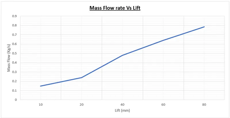
Mass Flow (Kg/s) |
Discharge (m3/hr) |
Kv |
Cv |
|
1 |
10 |
10 |
0.18307 |
9.81693 |
0.14894 |
0.5362 |
54.116 |
62.5581 |
|
2 |
20 |
10 |
0.47211 |
9.52789 |
0.23911 |
0.8608 |
88.186 |
101.9435 |
|
3 |
40 |
10 |
1.8759 |
8.1241 |
0.47755 |
1.7192 |
190.736 |
220.4913 |
|
4 |
60 |
10 |
3.3774 |
6.6226 |
0.6391 |
2.301 |
282.72 |
326.8247 |
|
5 |
80 |
10 |
5.132 |
4.868 |
0.78612 |
2.83 |
405.617 |
468.8932 |
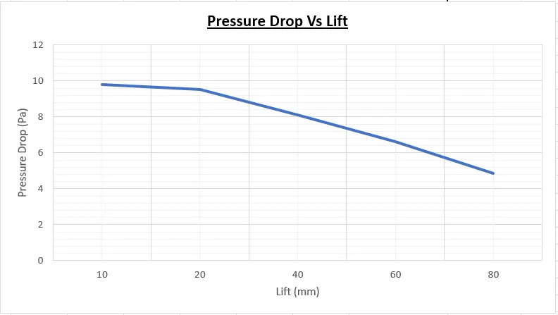
- Pressure Drop Vs Lift:
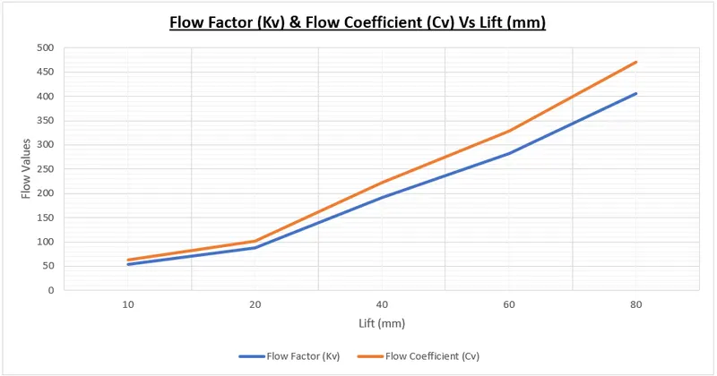
- Flow coefficient (Cv) & Flow Factor (Kv) Vs Lift:
- Mass Flow Vs Lift:
Conclusion:
- By parameterizing the lift variable, it becomes easy to simulate for different Lift condition.
- In case of simulation blowing up try changing the relaxation factor of Pressure and Momentum.
- As the lift value increases Outlet Pressure & Mass flow rate also increases, Pressure Drop decreases.
- Flow factor and Flow Coefficient also increases with increase in Lift