Week 8 - Simulation of a backward facing step in OpenFOAM
Aim: Perform a transient simulation over backward facing step geometry to study the effects of different grading factor and plot there result using plot over line command.
Code setup: Inside the terminal window
- Type 'tut' : it is shortcut for directly going to the tutorial directory of open Foam.
- Type ' cd incompressible/icoFoam/cavity' : cd is change directory and open the cavity folder inside the incompressible/icofoam directory.
- Type 'cp -r cavity/ $FOAM_RUN/cavity_test' : 'cp -r cavity' cp is for copy and '-r' is for recurssive. The stated command lets the cavity folder and files inside it to get copied inside the run folder and rename the file to cavity_test.
CASE 1 = Grading Factor: 1
Inorder to run the Backward facing step geometry we need to provide the initial boundary condition.
- Inside the cavity_test/cavity directory we have 3 directory 0, constant, system.
- 0 is the initial condition holding directory inside which we can get 'transportProperties' which could be viewd in notepad or text editor using gedit, setup the file accordingly.
- constant directory contains p(pressure) and U(velocity) editable files. This p & U files contain the boundary condition for pressure and velocity on the geometry walls.
- In system directory we have blockMeshDict, controlDict, fvSchemes, fvSolution. Of which we are interested in blockMeshdict and controlDict.
- blockMeshDict contains the geometry of the cavity problem so edit the file according to our geometry with the boundary condition.
- controlDict file contails the timestep, interval, dt, startTime and endTime.
transportProperties:
/*--------------------------------*- C++ -*----------------------------------*\
  =========                 |
  \\      /  F ield         | OpenFOAM: The Open Source CFD Toolbox
   \\    /   O peration     | Website:  https://openfoam.org
    \\  /    A nd           | Version:  9
     \\/     M anipulation  |
\*---------------------------------------------------------------------------*/
FoamFile
{
    format      ascii;
    class       dictionary;
    location    "constant";
    object      transportProperties;
}
// * * * * * * * * * * * * * * * * * * * * * * * * * * * * * * * * * * * * * //

nu              [0 2 -1 0 0 0 0] 0.01;


// ************************************************************************* //
- transportproperties file have the header and value of nu with its dimensions written within the square bracket.
p:
/*--------------------------------*- C++ -*----------------------------------*\
  =========                 |
  \\      /  F ield         | OpenFOAM: The Open Source CFD Toolbox
   \\    /   O peration     | Website:  https://openfoam.org
    \\  /    A nd           | Version:  9
     \\/     M anipulation  |
\*---------------------------------------------------------------------------*/
FoamFile
{
    format      ascii;
    class       volScalarField;
    object      p;
}
// * * * * * * * * * * * * * * * * * * * * * * * * * * * * * * * * * * * * * //

dimensions      [0 2 -2 0 0 0 0];

internalField   uniform 0;

boundaryField
{
    inlet
    {
        type            zeroGradient;
    }

    outlet
    {
        type            fixedValue;
        value 		 uniform 0;
    }

    topBottomAndSide
    {
        type            zeroGradient;
    }

    frontAndBack
    {
        type            empty;
    }
}

// ************************************************************************* //
- pressure at the different boundary is given 'zeroGradient' meaning normal pressure gradient is zero.
- since we are considering 2D problem so we provide empty condtion for front and back patch i.e. we are not interested in changes along z axis.
U:
/*--------------------------------*- C++ -*----------------------------------*\
  =========                 |
  \\      /  F ield         | OpenFOAM: The Open Source CFD Toolbox
   \\    /   O peration     | Website:  https://openfoam.org
    \\  /    A nd           | Version:  9
     \\/     M anipulation  |
\*---------------------------------------------------------------------------*/
FoamFile
{
    format      ascii;
    class       volVectorField;
    object      U;
}
// * * * * * * * * * * * * * * * * * * * * * * * * * * * * * * * * * * * * * //

dimensions      [0 1 -1 0 0 0 0];

internalField   uniform (0 0 0);

boundaryField
{
    inlet
    {
        type            fixedValue;
        value           uniform (1 0 0);
    }

    outlet
    {
        type            zeroGradient;
    }

    topBottomAndSide
    {
        type            noSlip;
    }

    frontAndBack
    {
        type            empty;
    }
}

// ************************************************************************* //
- Internal velocity field is uniform within the geometry hence mentioned uniform with initial zero value.
- In the inlet boundary the velocity is uniform and 1m/s along the x axis hence mentioned.
- Along the boundary walls of the geometry we assume noSlip condition.
blockMeshDict file:
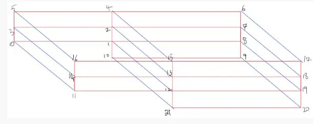
- The entire geometry is divided into 5 blocks, and each block is mentioned separtely as each block is 6 sided hence hex.

/*--------------------------------*- C++ -*----------------------------------*\
  =========                 |
  \\      /  F ield         | OpenFOAM: The Open Source CFD Toolbox
   \\    /   O peration     | Website:  https://openfoam.org
    \\  /    A nd           | Version:  9
     \\/     M anipulation  |
\*---------------------------------------------------------------------------*/
FoamFile
{
    format      ascii;
    class       dictionary;
    object      blockMeshDict;
}
// * * * * * * * * * * * * * * * * * * * * * * * * * * * * * * * * * * * * * //

convertToMeters 0.01;

vertices
(
    (0 0 0)//point 0
    (8 0 0)//point 1
    (8 0.5 0)//point 2
    (0 0.5 0)//point 3
    (8 1 0)//point 4
    (0 1 0)//point 5
    (20 1 0)//point 6
    (20 0.5 0)//point 7
    (20 0 0)//point 8
    (20 -1 0)//point 9
    (8 -1 0)//point 10

    (0 0 5)//point 11
    (8 0 5)//point 12
    (8 0.5 5)//point 13
    (0 0.5 5)//point 14
    (8 1 5)//point 15
    (0 1 5)//point 16
    (20 1 5)//point 17
    (20 0.5 5)//point 18
    (20 0 5)//point 19
    (20 -1 5)//point 20
    (8 -1 5)//point 21
);

blocks
(
    hex (0 1 2 3 11 12 13 14) (80 5 1) simpleGrading (1 1 1)
    hex (3 2 4 5 14 13 15 16) (80 5 1) simpleGrading (1 1 1)
    hex (2 7 6 4 13 18 17 15) (120 5 1) simpleGrading (1 1 1)
    hex (1 8 7 2 12 19 18 13) (120 5 1) simpleGrading (1 1 1)
    hex (10 9 8 1 21 20 19 12) (120 10 1) simpleGrading (1 1 1)
);

edges
(
);

boundary
(
    inlet
    {
        type wall;
        faces
        (
            (14 3 0 11)
            (16 5 3 14)
        );
    }
    outlet
    {
        type wall;
        faces
        (
            (6 17 18 7)
            (7 18 19 8)
            (8 19 20 9)
        );
    }
    topBottomAndSide
    {
        type wall;
        faces
        (
            (15 4 5 16)
            (17 6 4 15)

            (11 0 1 12)
            (21 10 9 20)

            (12 1 10 21)
        );
    }
    frontAndBack
    {
        type empty;
        faces
        (
            (15 16 14 13)
            (13 14 11 12)
            (17 15 13 18)
            (18 13 12 19)
            (19 12 21 20)

            (5 4 2 3)
            (3 2 1 0)
            (4 6 7 2)
            (2 7 8 1)
            (1 8 9 10)
        );
    }
);

mergePatchPairs
(
);- Here we define the coordinates of the geometry according to the cartiesian coordinate system.
- The boundaries are named by giving the cooresponding face coordinate and the type of boundary.
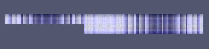
- Each block is divided into 200 cells along x axis and 10 cells along y axis, it is nothing but the mesh size.
- The grading factor is mentioned at the end of the hex i.e. simpleGrading (1 1 1)
Grading factor = End cell size / start cell size
for GF=1 means start and end cell both are same in size
controlDict:
/*--------------------------------*- C++ -*----------------------------------*\
  =========                 |
  \\      /  F ield         | OpenFOAM: The Open Source CFD Toolbox
   \\    /   O peration     | Website:  https://openfoam.org
    \\  /    A nd           | Version:  9
     \\/     M anipulation  |
\*---------------------------------------------------------------------------*/
FoamFile
{
    format      ascii;
    class       dictionary;
    location    "system";
    object      controlDict;
}
// * * * * * * * * * * * * * * * * * * * * * * * * * * * * * * * * * * * * * //

application     icoFoam;

startFrom       startTime;

startTime       0;

stopAt          endTime;

endTime         .1;

deltaT          0.00004;

writeControl    timeStep;

writeInterval   100;

purgeWrite      0;

writeFormat     ascii;

writePrecision  6;

writeCompression off;

timeFormat      general;

timePrecision   6;

runTimeModifiable true;


// ************************************************************************* //
- This file consist of the dt, timestep and interval basically this file helps to decide the simulation time.
- Before changing the dt value it is adivseable to check the courant no. as it decides the stability of the simulation and prevents the solution from blowing up.
- courant no. = dt/ dx , so according to the GF value decide the smallest cell size, for stability courant no. < 1.
Output1:
- After the blockmesh file is updated save and close the file. Then type 'blokMesh' in the terminal window, if no error rise then the meshing is perfect.
- Inorder to view the mesh geometry type 'paraFoam' in the terminal window, below figure gets appeared.
Mesh Geometry:
- Then type 'icoFoam' in the terminal window icoFoam is nothing but the solver which is used to solve the problem.
- IcoFoam solver is used for laminar, isothermal, incompressible flow.
- Type 'paraFoam' in the terminal window to postprocess the results.
velocity Distribution:

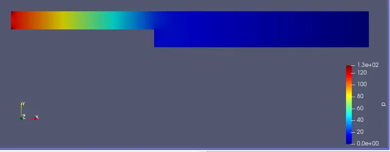
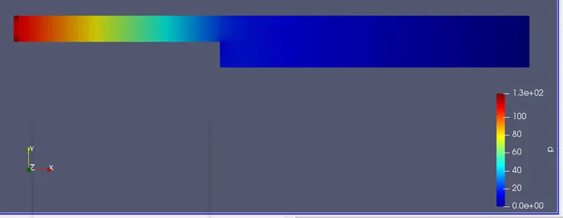
Pressure Distribution:
Plot over Line command:
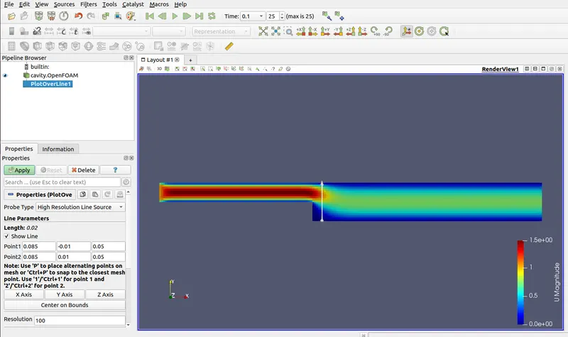
- In the parafoam window click ctrl+spacebar and type plot over line then mention coordinate of two points within the geometry where the results need to be viewed.
- Reduce the resolution to 100 data point, the data from these points are ploted in graph.
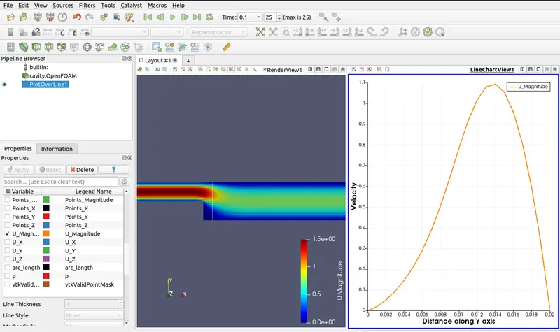
- The parameter which we need to plot is selected
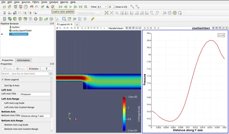
- Axis title are given in this window.
Grading Factor= 0.5
The grading factor along the boundary wall is consider to be 0.5, the end wall is size is 1 and the start wall cell is 2.
blockMeshDict:
/*--------------------------------*- C++ -*----------------------------------*\
  =========                 |
  \\      /  F ield         | OpenFOAM: The Open Source CFD Toolbox
   \\    /   O peration     | Website:  https://openfoam.org
    \\  /    A nd           | Version:  9
     \\/     M anipulation  |
\*---------------------------------------------------------------------------*/
FoamFile
{
    format      ascii;
    class       dictionary;
    object      blockMeshDict;
}
// * * * * * * * * * * * * * * * * * * * * * * * * * * * * * * * * * * * * * //

convertToMeters 0.01;

vertices
(
    (0 0 0)//point 0
    (8 0 0)//point 1
    (8 0.5 0)//point 2
    (0 0.5 0)//point 3
    (8 1 0)//point 4
    (0 1 0)//point 5
    (20 1 0)//point 6
    (20 0.5 0)//point 7
    (20 0 0)//point 8
    (20 -1 0)//point 9
    (8 -1 0)//point 10

    (0 0 5)//point 11
    (8 0 5)//point 12
    (8 0.5 5)//point 13
    (0 0.5 5)//point 14
    (8 1 5)//point 15
    (0 1 5)//point 16
    (20 1 5)//point 17
    (20 0.5 5)//point 18
    (20 0 5)//point 19
    (20 -1 5)//point 20
    (8 -1 5)//point 21
);

blocks
(
    hex (0 1 2 3 11 12 13 14) (80 5 1) simpleGrading (.5 2 1)
    hex (3 2 4 5 14 13 15 16) (80 5 1) simpleGrading (.5 .5 1)
    hex (2 7 6 4 13 18 17 15) (120 5 1) simpleGrading (2 .5 1)
    hex (1 8 7 2 12 19 18 13) (120 5 1) simpleGrading (2 2 1)
    hex (10 9 8 1 21 20 19 12) (120 10 1) simpleGrading (2 2 1)
);

edges
(
);

boundary
(
    inlet
    {
        type wall;
        faces
        (
            (14 3 0 11)
            (16 5 3 14)
        );
    }
    outlet
    {
        type wall;
        faces
        (
            (6 17 18 7)
            (7 18 19 8)
            (8 19 20 9)
        );
    }
    topBottomAndSide
    {
        type wall;
        faces
        (
            (15 4 5 16)
            (17 6 4 15)

            (11 0 1 12)
            (21 10 9 20)

            (12 1 10 21)
        );
    }
    frontAndBack
    {
        type empty;
        faces
        (
            (15 16 14 13)
            (13 14 11 12)
            (17 15 13 18)
            (18 13 12 19)
            (19 12 21 20)

            (5 4 2 3)
            (3 2 1 0)
            (4 6 7 2)
            (2 7 8 1)
            (1 8 9 10)
        );
    }
);

mergePatchPairs
(
);
Output2:
Mesh Geometry:
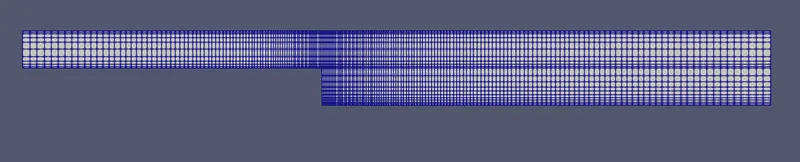
- The mesh are seen closer towards the step and near the wall of the geometry due to grading factor.

Velocity Distribution:
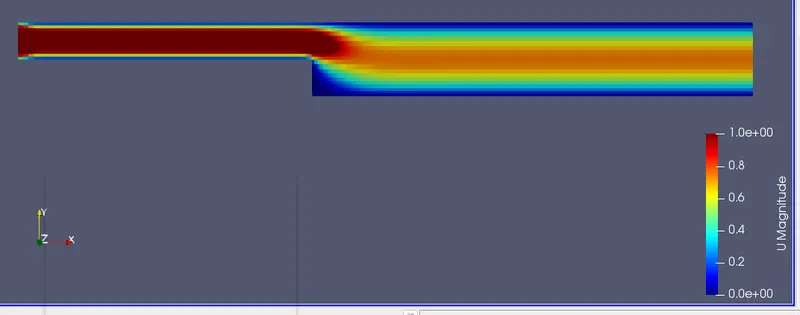
Pressure Distribution:
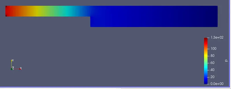
Velocity Graph:
Pressure Graph:
Grading Factor= 0.2
/*--------------------------------*- C++ -*----------------------------------*\
  =========                 |
  \\      /  F ield         | OpenFOAM: The Open Source CFD Toolbox
   \\    /   O peration     | Website:  https://openfoam.org
    \\  /    A nd           | Version:  9
     \\/     M anipulation  |
\*---------------------------------------------------------------------------*/
FoamFile
{
    format      ascii;
    class       dictionary;
    object      blockMeshDict;
}
// * * * * * * * * * * * * * * * * * * * * * * * * * * * * * * * * * * * * * //

convertToMeters 0.01;

vertices
(
    (0 0 0)//point 0
    (8 0 0)//point 1
    (8 0.5 0)//point 2
    (0 0.5 0)//point 3
    (8 1 0)//point 4
    (0 1 0)//point 5
    (20 1 0)//point 6
    (20 0.5 0)//point 7
    (20 0 0)//point 8
    (20 -1 0)//point 9
    (8 -1 0)//point 10

    (0 0 5)//point 11
    (8 0 5)//point 12
    (8 0.5 5)//point 13
    (0 0.5 5)//point 14
    (8 1 5)//point 15
    (0 1 5)//point 16
    (20 1 5)//point 17
    (20 0.5 5)//point 18
    (20 0 5)//point 19
    (20 -1 5)//point 20
    (8 -1 5)//point 21
);

blocks
(
    hex (0 1 2 3 11 12 13 14) (80 5 1) simpleGrading (.2 5 1)
    hex (3 2 4 5 14 13 15 16) (80 5 1) simpleGrading (.2 .2 1)
    hex (2 7 6 4 13 18 17 15) (120 5 1) simpleGrading (5 .2 1)
    hex (1 8 7 2 12 19 18 13) (120 5 1) simpleGrading (5 5 1)
    hex (10 9 8 1 21 20 19 12) (120 10 1) simpleGrading (5 5 1)
);

edges
(
);

boundary
(
    inlet
    {
        type wall;
        faces
        (
            (14 3 0 11)
            (16 5 3 14)
        );
    }
    outlet
    {
        type wall;
        faces
        (
            (6 17 18 7)
            (7 18 19 8)
            (8 19 20 9)
        );
    }
    topBottomAndSide
    {
        type wall;
        faces
        (
            (15 4 5 16)
            (17 6 4 15)

            (11 0 1 12)
            (21 10 9 20)

            (12 1 10 21)
        );
    }
    frontAndBack
    {
        type empty;
        faces
        (
            (15 16 14 13)
            (13 14 11 12)
            (17 15 13 18)
            (18 13 12 19)
            (19 12 21 20)

            (5 4 2 3)
            (3 2 1 0)
            (4 6 7 2)
            (2 7 8 1)
            (1 8 9 10)
        );
    }
);

mergePatchPairs
(
);
Output3:
Mesh Geometry:
Velocity Distribution:
Pressure Distribution:
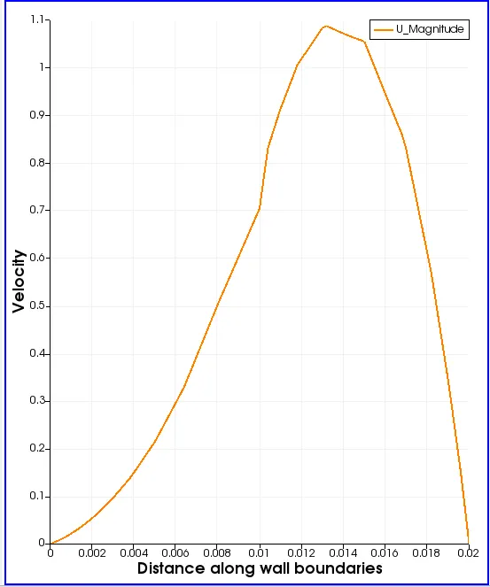
Velocity Profile:
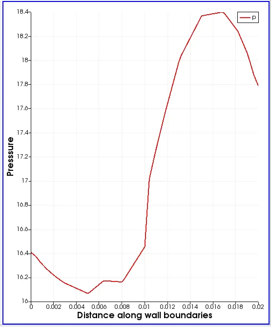
Pressure Profile:
Results:
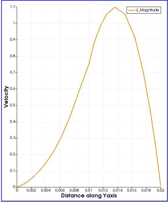
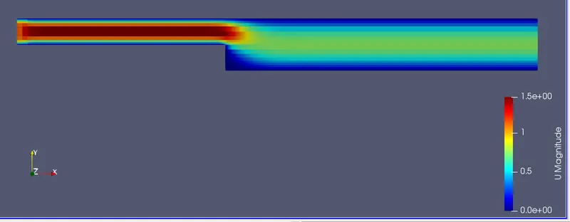
- It is seen from the velocity graph that it gradually increases along the step and then it hits the maximum velocity, then the velocity starts to fall instantly towards the upper boundary wall.
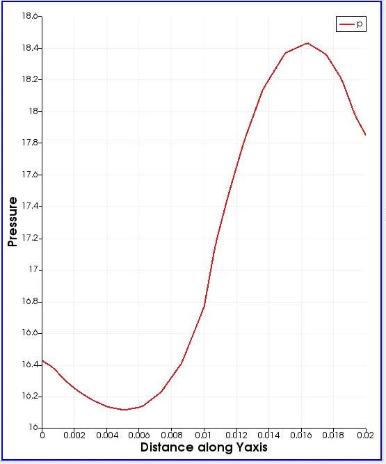
- The pressure graph starts to take the form of s shaped curve from the lower to upper wall boundary.
- As the grading factor decreases the smoothness of the curve also decreses.
- The pressure and velocity curve for the three case is similar hence the results does not depend on the grading factor.