Week 9 - Parametric study on Gate valve.
The aim of this exercise is to conduct a parametric study on a gate valve by simulating flow of fluid through the valve and calculating the rate of flow of fluid through the valve for given percentage of opening. For this, We have to import the model of the valve into spaceclaim and then we have to first set the gate of the valve at 10mm opeing by using the move command. Then, after providing the necessary lifting, we now generate the flow volume by using the volume extract option from prepare. We also provide fluid volume at either sides which matches the inlet and outlet flow path OD correspondingly and then extract by a factor of 800mm at both sides to set up a condition of a pipe joint. Now the flow volume is generated and we can adjust the height or the percentage opening of the gate by adjusting the height parameter and then matching the volume accordingly. Now, the volume has been generated for meshing.
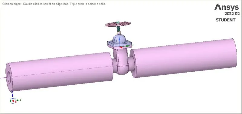
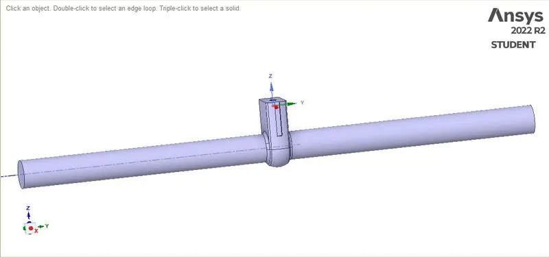
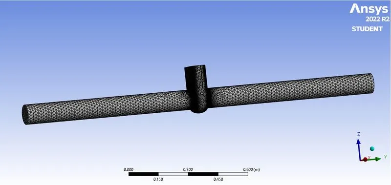
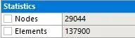
After the volume has been generated, we move onto meshing. First, we create named selections for the faces of inlet, outlet and then we set the sizing parameter. Now, we generate the mesh.
After the mesh has been generated, we move onto fluent solver and now we have to set the boundary conditions and the necessary parameters for the purpose of simulation. At first, we specify the material inside the volume as water from the fluent database and then copy the material. Then, we use steady state, pressure based absolute velocity formation solver with gravity enabled. We set the fluid as water from cell zones. Now, we choose k-epsilon viscous model as for the solver with realizable and scalable wall functions enabled. Now, we can set the boundary conditions from cell zoned and boundaires and set the inlet as pressure inlet and then defining the gauge pressure as 10Pa. Now, we can cross check the other boundary conditions to be set exactly the way required and then move onto initializing. We initialize the solving from options an from inlet and then set up the contour plots that we need and finally the animation for the particular contour plot. This method can be followed for the rest of percentage openings to find the flow rate.
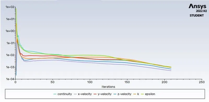
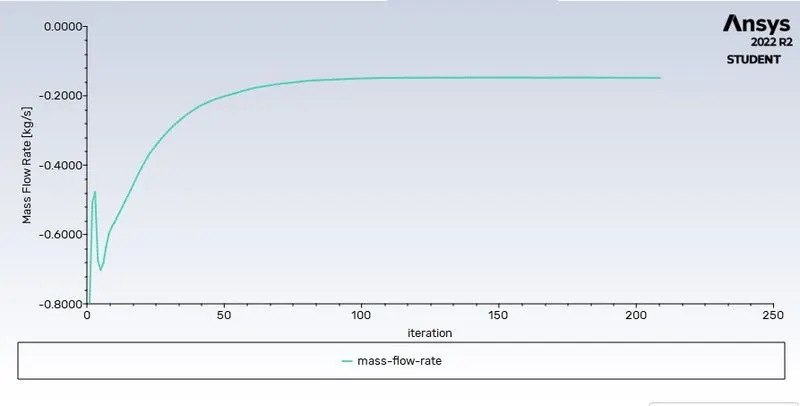
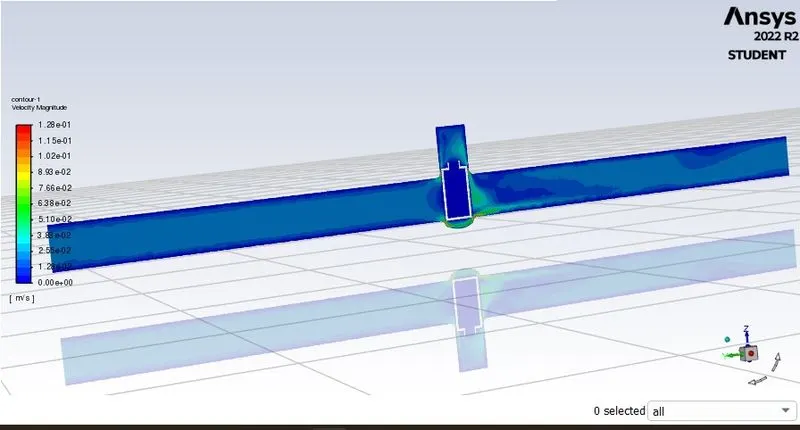
For 10% opening:
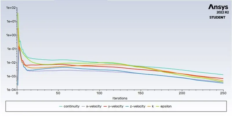
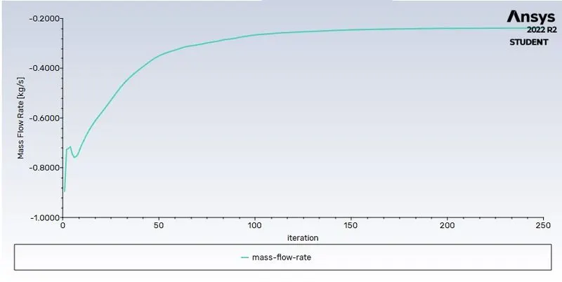
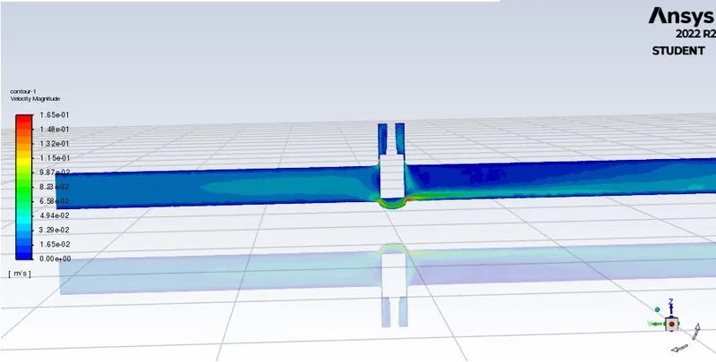
For 20% opening:
`Kv = Q*root()((SG)/(DeltaP))`
Cv = Kv/0.865
| Lift % | Mass flow rate | kv | cv |
| 10 | 0.148 | 53.3 | 61.6 |
| 20 | 0.237 | 85.5 | 98.8 |
| 30 | 0.364 | 131.09 | 151.5 |
| 40 | 0.473 | 170.3 | 196.9 |
| 50 | 0.610 | 219.8 | 254.1 |
| 60 | 0.648 | 233.3 | 269.7 |
| 70 | 0.729 | 262.4 | 303.4 |
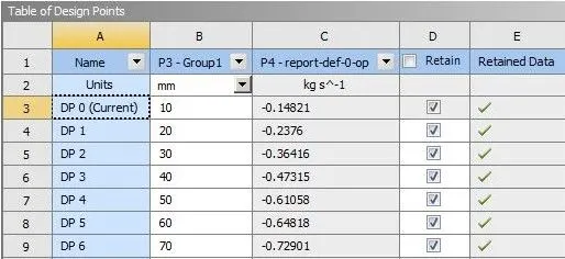
From the plots, it is evident that as the percentage opening increases, the mass flow rate also increases and the negative sign shows the flow exiting from the outlet of the valve. Also, the velocity of flow increases and pressure decreases as the internal components of the valve are no longer under pressure.