Week 9 - Parametric study on Gate valve.
AIM:- The project aims at the parametric study of a Gate Valve at different valve opening settings.
OBJECTIVES:- The project objectives are -
- Perform a parametric study on the gate valve simulation by setting the opening from 10 % to 80%.
- Obtain the mass flow rates at the outlet for each design point.
- Calculate the flow coefficient and flow factor for each opening and plot the graph.
- Discuss the results of the mass flow rate and flow coefficient.
PROJECT DESCRIPTION:- A gate valve is the most common valve for water supply systems. It represents a linear-motion isolation valve and has the function to stop or allow the flow. Gate valves got their name from the closure element sliding into the flow stream to provide shutoff and, therefore, acting like a gate. Gate valves are used to isolate specific areas of the water supply network during maintenance, repair works, and new installations, as well as to reroute water flow throughout the pipeline.
A gate valve has a simple design and can be applied in many low-pressure-drop services, which makes it one of the most common valves in use today. Gate valves are designed as full-port valves. This means that the valve port is of the same size as the inner diameter of the connecting pipe. A resilient seated gate valve with a non-rising spindle consists of the following parts:
- wedge
- ductile iron valve body
- seating area
- stem (spindle)
- spindle bearing
- bonnet
- packing.
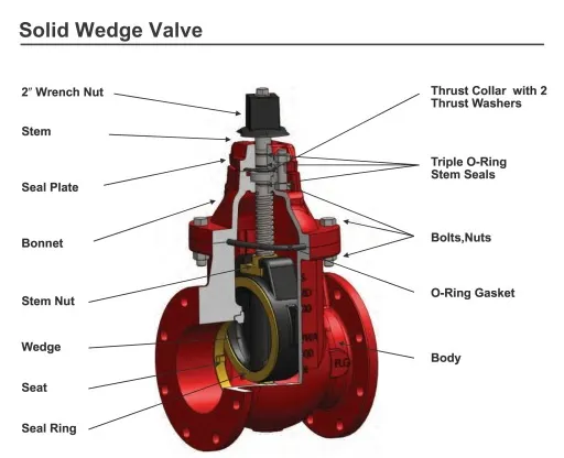
Types of Gate Valves:- Based on Construction, Gate valves for water supply systems can generally be divided into the following types-
- By wedge: parallel gate valves and wedge gate valves
- By seat: metal seat or resilient seated gate valves
- By stem: with rising or non-rising stem.
For our simulation, we take a wedge gate valve because most gate valves used in water distribution systems are wedge gate valves. Wedge gate valves are so called because of a wedge-shaped gate. The wedge has ribs on both sides and is guided by the slots in the gate valve body. The wedge guides serve the following purposes:
- To transfer the axial loads imposed on the wedge by the medium to the valve body
- To enable a low-friction movement of the wedge in the radial direction
- To prevent the wedge from rotation while traveling between open/closed valve positions (serving as an anti-twist lock).
In this project, we need to calculate the mass flow rate at the outlet and also the flow coefficient and flow factor for each opening.
Mass Flow Rate:- The mass flow rate is the mass of a liquid substance passing per unit of time. In other words, the mass flow rate is defined as the rate of movement of liquid passing through a unit area. The mass flows directly depend on the density, velocity of the liquid, and area of the cross-section. It is the movement of mass per unit of time. The mass flow is denoted by m and the units in kg/s.
The mass flow formula is given by,
`m= ρVA`
Where, ρ = Density of fluid, V = Velocity of the liquid, and A = Area of cross-section.
Valve Flow Coefficient:- The valve flow coefficient is an essential measurement that helps you calculate how much fluid can pass through a valve. The valve flow coefficient (Cv) can measure the rate at which any gas or liquid can pass through a valve. Flow Coefficient(Cv) is defined as the number of gallons per minute (GPM) at 60°F that will pass through a fully open valve with a pressure drop of 1 psi.
For incompressible fluids like water, a close approximation can be found mathematically by the following equation;
`C_v=Q√(S_G/(∆P))`
Where,
- Cv = Valve flow coefficient
- Q = Fluid flow, (also given by Area of pipe x mean velocity)
- SG = Specific gravity of fluid relative to water @ 60°F
- ∆P = Pressure drop (P1 – P2) across the control valve at maximum flow, psi
The equation shows that the flow rate varies as the square root of the differential pressure across the control valve. The greater the pressure drop higher will be the flow rate.
Valve Flow Factor:- The metric equivalent of the flow coefficient - Cv - is based on the SI system and is called the flow factor(Kv). The flow factor(Kv) is defined as the flow of water with a temperature ranging from 5 oC - 30 oC through a valve in cubic meters per hour (m3/h) with a pressure drop of 1 bar. And the relation between `C_v` and `K_v` is
`K_v = 0.862 C_v`
and
`K_v=Q√(S_G/(∆P))`
After knowing all these things, now we can move towards our simulation where we perform a parametric study on the gate valve simulation by setting the opening from 10 % to 80%. The step of our simulation is -
- Geometry and Meshing
- Setting up the physics and solve the equations
- Postprocessing
Geometry and Meshing:-
Geometry prepare:-
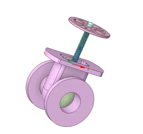
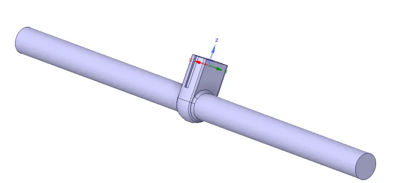
Here is our geometry, which is the Gate Valve we need to simulate-
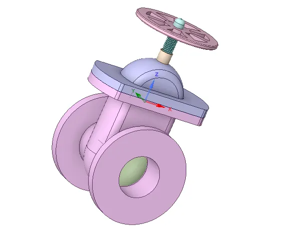
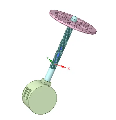
There is a gate disk inside the bottom part, which controls the flow of fluid-
Now we move our gate disk 10 mm in upward direction-
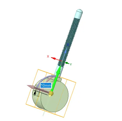
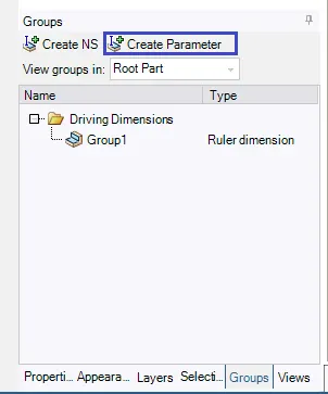
In order to change the upward movement of the gate disk, we need to click on the Create Parameter option.
We hide the bonnet to select the fluid region-
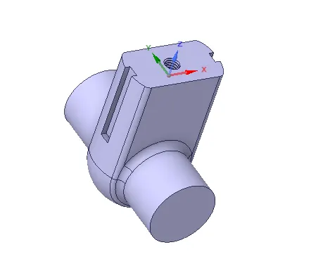
By using Volume Extract method, we create the fluid volume.
To increase the length of the inlet and the outlet pipe, we click on the pull option and increase the length to 800 mm.
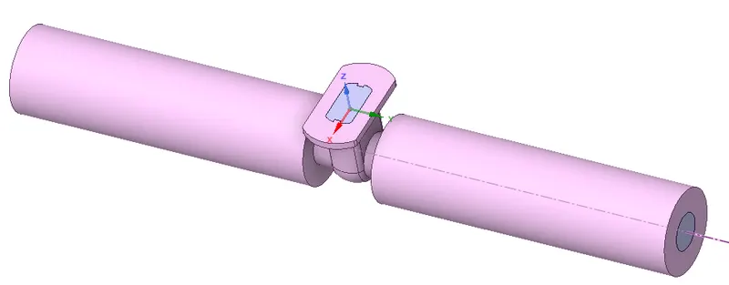
It is the fluid volume inside the bottom geometry, and it is in this fluid volume that meshing must be performed-
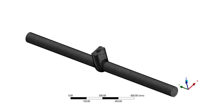
Meshing:- We meshed the geometry by taking the element size as 0.7mm.
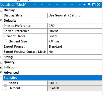
It is the meshing details where we can see the number of nodes and elements-
Setting up the physics and solve the equations:-
- Pressure-based solvers and absolute velocity are used.
- It is a 3D simulation.
- Steady-state simulation is performed.
- The gravity is enabled in the -ve Z-axis.
- The Realizable k-epsilon model is taken as the viscous model. And for better wall treatment, a scalable wall function is used.
- Here we take water as fluid.
- Instead of taking the velocity inlet, we will use the pressure inlet and set the inlet pressure to 10 Pa. A velocity of 0.14155 m/s is automatically calculated by fluent.
- In pressure-velocity coupling, a Coupled scheme is used. For the momentum, a second-order upwind scheme is used and for pressure, the second order is selected. In the case of Turbulent Kinetic Energy and Turbulent Dissipation Rate, a first-order scheme is chosen.
Report:- It's a report provided by the fluent for the Gate Disk's 10 mm upward movement.
Fluent
Version: 3d, dp, pbns, rke (3d, double precision, pressure-based, realizable k-epsilon)
Release: 22.1.0
Title:


Models
------

   Model                        Settings
   ------------------------------------------------------------------
   Space                        3D
   Time                         Steady
   Viscous                      Realizable k-epsilon turbulence model
   Wall Treatment               Scalable Wall Function
   Heat Transfer                Disabled
   Solidification and Melting   Disabled
   Species                      Disabled
   Coupled Dispersed Phase      Disabled
   NOx Pollutants               Disabled
   SOx Pollutants               Disabled
   Soot                         Disabled
   Mercury Pollutants           Disabled
   Structure                    Disabled
   Acoustics                    Disabled
   Eulerian Wall Film           Disabled
   Potential/Li-ion Battery     Disabled
   Multiphase                   Disabled


Material Properties
-------------------

   Material: water-liquid (fluid)

      Property                        Units      Method     Value(s)
      --------------------------------------------------------------
      Density                         kg/m^3     constant   998.2
      Cp (Specific Heat)              J/(kg K)   constant   4182
      Thermal Conductivity            W/(m K)    constant   0.6
      Viscosity                       kg/(m s)   constant   0.001003
      Molecular Weight                kg/kmol    constant   18.0152
      Thermal Expansion Coefficient   K^-1       constant   0
      Speed of Sound                  m/s        none       #f

   Material: aluminum (solid)

      Property               Units      Method     Value(s)
      -----------------------------------------------------
      Density                kg/m^3     constant   2719
      Cp (Specific Heat)     J/(kg K)   constant   871
      Thermal Conductivity   W/(m K)    constant   202.4


Cell Zone Conditions
--------------------

   Zones

      name            id   type
      --------------------------
      volume_volume   3    fluid

   Setup Conditions

      volume_volume

         Condition       Value
         ---------------------
         Frame Motion?   no


Boundary Conditions
-------------------

   Zones

      name                 id   type
      -----------------------------------------
      inlet                6    pressure-inlet
      wall-volume_volume   1    wall
      outlet               7    pressure-outlet

   Setup Conditions

      inlet

         Condition                   Value
         ---------------------------------
         Gauge Total Pressure [Pa]   10

      wall-volume_volume

         Condition                  Value
         ------------------------------------------
         Wall Motion                Stationary Wall
         Shear Boundary Condition   No Slip

      outlet

         Condition   Value
         -----------------


Solver Settings
---------------

   Equations

      Equation     Solved
      -------------------
      Flow         yes
      Turbulence   yes

   Numerics

      Numeric                         Enabled
      ---------------------------------------
      Absolute Velocity Formulation   yes

   Pseudo Time Explicit Relaxation Factors

      Variable                     Relaxation Factor
      ----------------------------------------------
      Density                      1
      Body Forces                  1
      Turbulent Kinetic Energy     0.75
      Turbulent Dissipation Rate   0.75
      Turbulent Viscosity          1
      Explicit Momentum            0.5
      Explicit Pressure            0.5

   Linear Solver

      Variable                     Solver Type   Termination Criterion   Residual Reduction Tolerance
      -----------------------------------------------------------------------------------------------
      Flow                         F-Cycle       0.1
      Turbulent Kinetic Energy     F-Cycle       0.1
      Turbulent Dissipation Rate   F-Cycle       0.1

   Pressure-Velocity Coupling

      Parameter                               Value
      -----------------------------------------------
      Type                                    Coupled
      Pseudo Time Method (Global Time Step)   yes

   Discretization Scheme

      Variable                     Scheme
      ------------------------------------------------
      Pressure                     Second Order
      Momentum                     Second Order Upwind
      Turbulent Kinetic Energy     First Order Upwind
      Turbulent Dissipation Rate   First Order Upwind

   Solution Limits

      Quantity                         Limit
      ---------------------------------------
      Minimum Absolute Pressure        1
      Maximum Absolute Pressure        5e+10
      Minimum Temperature              1
      Maximum Temperature              5000
      Minimum Turb. Kinetic Energy     1e-14
      Minimum Turb. Dissipation Rate   1e-20
      Maximum Turb. Viscosity Ratio    100000
Postprocessing the results:-
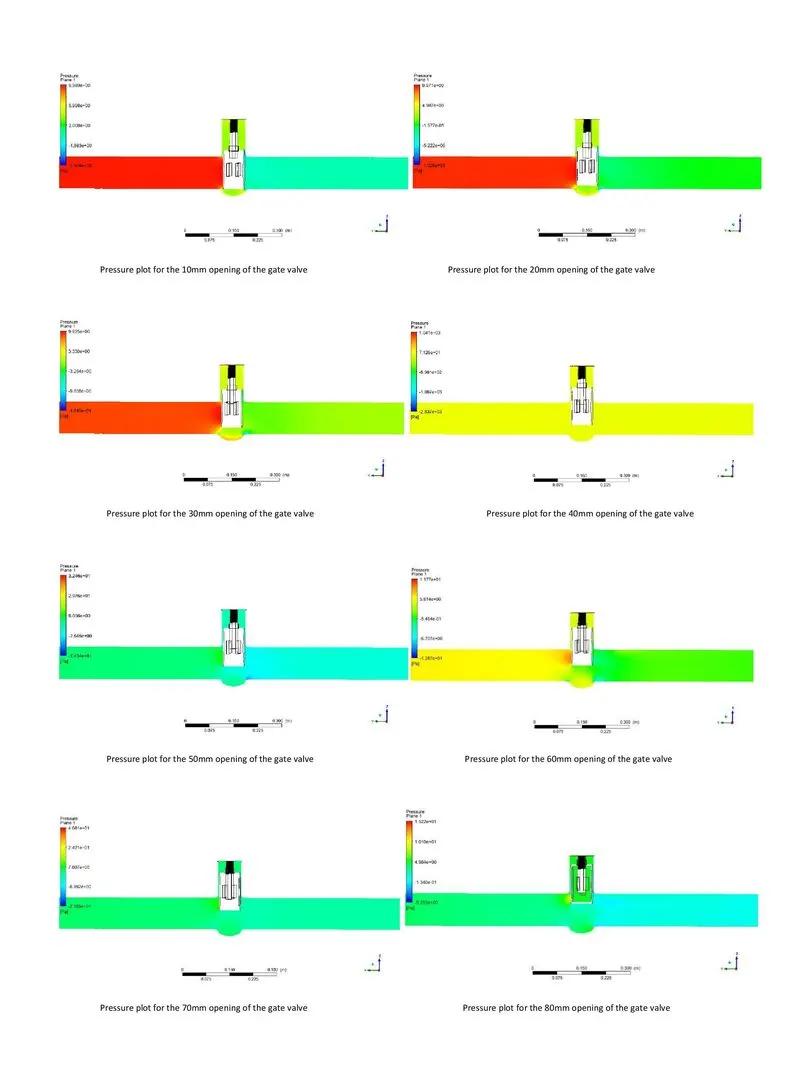
Pressure Plots for all design points:-
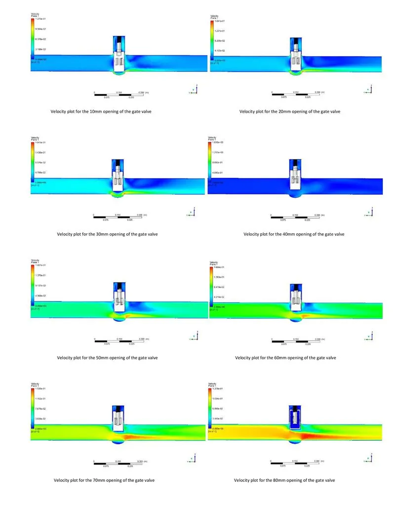
Velocity Plots for all design points:-
Mass Flow rate and Pressure drop values for all design points:-
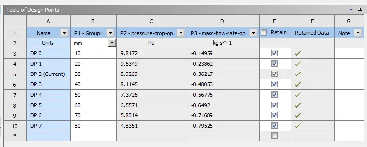
So, using those points we calculate flow rate, `K_v`, and `C_v`. Firstly, we calculate for 10mm lift of gate disk-
We know from the flow factor equation,
`K_v=Q.√(S_G/(∆P))`
And we know the mass flow rate,
`m^'= ρ*Q` [Here, `ρ` is the density of water, and Q is flow rate]
`=> Q= (m')/ρ = 0.14959/997`= = 0.00015 m3/s = 0.54 m3/h
Since, 1bar = 100000 Pa
`=>`9.8172 Pa = 0.000098172 bar
So,
`K_v=Q*√(S_G/(∆P))` = `0.54*(1/ 0.000098172)^0.5` = 54.5
and
`C_v=K_(v )/0.862= 54.5/0.862` = 63.23
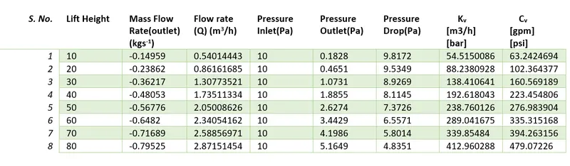
All calculated flow coefficients and flow factors are shown here, and we used Excel to calculate flow rate, `K_v`, and `C_v`.
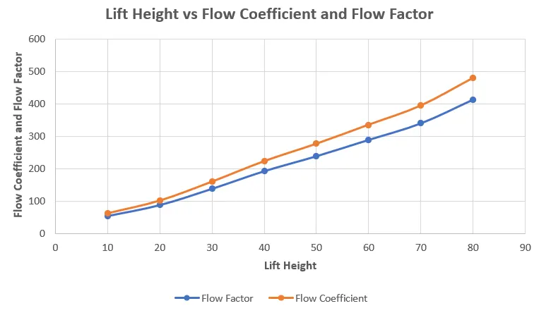
Lift Height vs Flow Coefficient and Flow Factor Plot:-
Lift Height vs Mass Flow Rate Plot:-
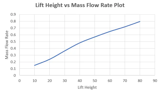
CONCLUSION:- Based on the results, we can conclude the following:
- As soon as the gate disk is lifted, the pressure difference between the inlet and outlet is very large, as the mass flow rate is very low at that time. As the lift height of the gate disk increases, the mass flow rate increases, and the pressure difference decreases drastically.
- In the table, we can see that Fluent gives us a negative mass flow rate, which is due to fluid escaping through the outlet.
- With the increase in lift height, the Flow factor and Flow coefficient also increase. This flow coefficient helps to calculate how much fluid can pass through a valve.
- By using a parametric study, we were able to reach our results very quickly.
- Since gate valves are isolation valves, they must be used either in the fully open or fully closed position and must not be deployed to regulate the water flow. When throttling a gate valve, turbulent flow rates through the valve body can cause vibration and cavitation, damaging the wedge and the seat, which will eventually lead to leakages and worse sealing capacities.