Week 8 - Simulation of a backward facing step in OpenFOAM
Aim:- Our project aims to simulate an incompressible-laminar-viscous flow through the backward-facing step geometry.
OBJECTIVE:- Objective is to create a geometry through which an incompressible-laminar-viscous flow occurs. And then, we divide our simulation into two parts, in the first case, we do not apply the grading factor in the block mesh part and observe the simulation how it happens, and then in the second case, we observe the simulation after applying the grading factor. And we compare both cases.
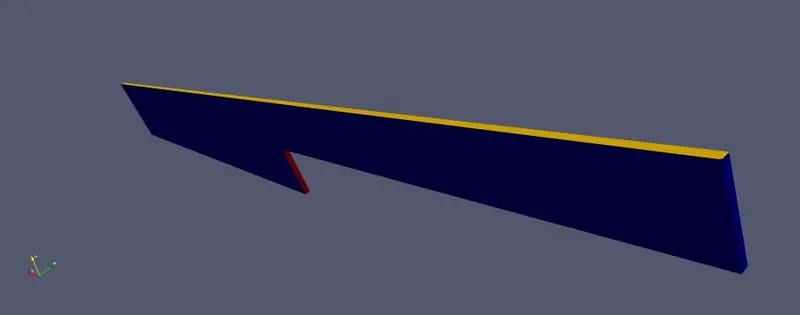
DETAIL DESCRIPTION OF THE PROJECT:- So first of all, we have to choose the solver. Here we should perform the transient solution, and we are going to simulate the incompressible-laminar-viscous flow through the backward-facing step geometry. So from all this description, we conclude that icoFoam is the type of solver that we need. Because icoFoam is a transient solver for the incompressible-laminar flow of Newtonian fluid. So we choose the cavity directory in icoFoam solver, and now we change the blockMesh file which is present in the system folder of the cavity directory to create our geometry. This is how the geometry looks like-
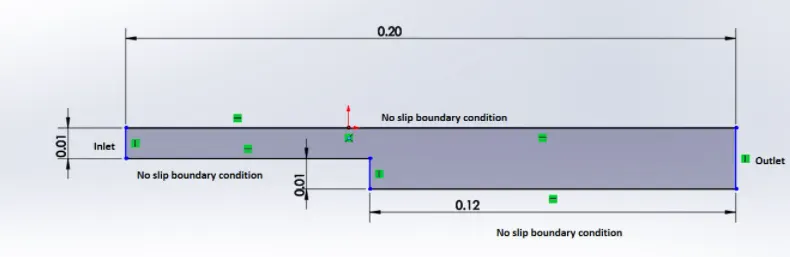
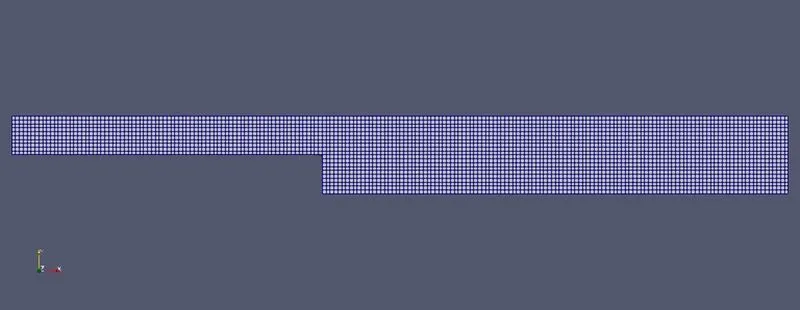
Mesh specification
- Number of cells along the x direction (longer dimension) = 200
- Number of cells along the longer y direction = 20;
- Here we use the grading factor 1, 0.2, and 0.5
To create this geometry we devide it into 5 blocks like this-
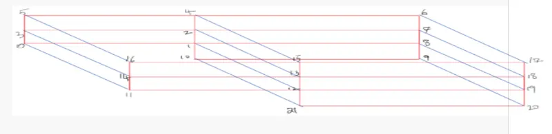
So in block mesh file first we create the vertices mens to create the 5 blocks we have to specify the points . Then we create those 5 blocks like the previos picture. In the blockMesh file to create a block we have to specify three parts, let's consider a block
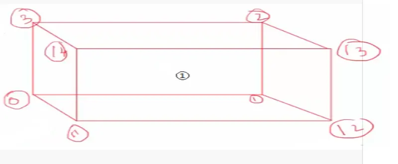
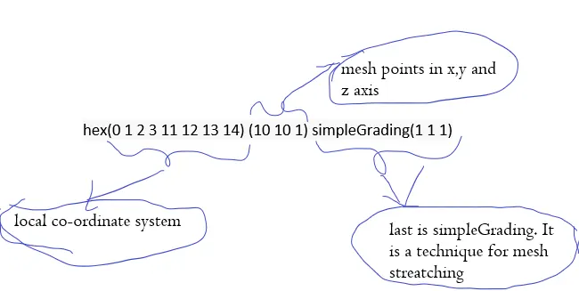
And, thus we write all 5 blocks in the file. After creating the blocks we need to specify the boundary like an inlet, an outlet of the flow, and the walls. Since it is a 2d simulation, we are not focusing on the z-direction so that’s why we are not mentioning the mesh point number in the z-direction, and also we keep the front and backside type as empty in the boundary conditions. To mention the faces of inlet, outlet, top, bottom, sidewall, and frontAndBack we use a technique. Each block face is defined by a list of 4 vertex numbers. The order in which the vertices are given must be such that, looking from inside the block and starting with any vertex, the face must be traversed in a clockwise direction and looking from outside the block and starting with any vertex, the face must be traversed in a anti-clockwise direction to define the other vertices. So thus we define the blockMesh file.
So the Blockmesh file is
/*--------------------------------*- C++ -*----------------------------------*
  =========                 |
        /  F ield         | OpenFOAM: The Open Source CFD Toolbox
       /   O peration     | Website:  https://openfoam.org
      /    A nd           | Version:  9
     /     M anipulation  |
*---------------------------------------------------------------------------*/
FoamFile
{
    format      ascii;
    class       dictionary;
    object      blockMeshDict;
}
// * * * * * * * * * * * * * * * * * * * * * * * * * * * * * * * * * * * * * //

convertToMeters 0.001;

vertices
(
    (0 0 0)  //0
    (80 0 0) //1
    (80 5 0) //2
    (0 5 0)  //3
    (80 10 0)//4
    (0 10 0)//5
    (200 10 0)//6
    (200 5 0)//7
    (200 0 0)//8
    (200 -10 0)//9
    (80 -10 0)//10

    (0 0 1) //11
    (80 0 1) //12
    (80 5 1) //13
    (0 5 1)  //14
    (80 10 1)//15
    (0 10 1)//16
    (200 10 1)//17
    (200 5 1)//18
    (200 0 1)//19
    (200 -10 1)//20
    (80 -10 1)//21
);

blocks
(
    hex (0 1 2 3 11 12 13 14) (80 5 1) simpleGrading (1 1 1)
    hex (3 2 4 5 14 13 15 16) (80 5 1) simpleGrading (1 1 1)

    hex (2 7 6 4 13 18 17 15) (120 5 1) simpleGrading (1 1 1)
    hex (1 8 7 2 12 19 18 13) (120 5 1) simpleGrading (1 1 1)
    hex (10 9 8 1 21 20 19 12) (120 10 1) simpleGrading (1 1 1)
);

edges
(
);

boundary
(
    inlet
    {
        type patch;
        faces
        (
            (0 11 14 3)
            (3 14 16 5)
        );
    }

    outlet
    {
        type patch;
        faces
        (
            (9 8 19 20)
            (8 7 18 19)
            (7 6 17 18)
        );
    }

    topwalls
    {
        type wall;
        faces
        (
            (4 5 16 15)
            (6 4 15 17)
        );
    }

    bottomwalls
    {
        type wall;
        faces
        (

            (12 11 0 1)
            (10 9 20 21)
        );
    }

    stepsidewall
    {
        type wall;
        faces
        (

            (10 21 12 1)
        );
    }

    frontAndBack
    {
        type empty;
        faces
        (
            (13 15 16 14)
            (12 13 14 11)
            (18 17 15 13)
            (19 18 13 12)
            (20 19 12 21)

            (2 3 5 4)
            (1 0 3 2)
            (7 2 4 6)
            (8 1 2 7)
            (9 10 1 8)
        );
    }
);

mergePatchPairs
(

);
// ************************************************************************* //
After creating the blockMesh file the geometry looks like
this is how the mesh looks like
Pressure file
Pressure for incompressible solvers, this field is actually the pressure normalized by constant fluid density.
/*--------------------------------*- C++ -*----------------------------------*
  =========                 |
        /  F ield         | OpenFOAM: The Open Source CFD Toolbox
       /   O peration     | Website:  https://openfoam.org
      /    A nd           | Version:  9
     /     M anipulation  |
*---------------------------------------------------------------------------*/
FoamFile
{
    format      ascii;
    class       volScalarField;
    object      p;
}
// * * * * * * * * * * * * * * * * * * * * * * * * * * * * * * * * * * * * * //

dimensions      [0 2 -2 0 0 0 0];

internalField   uniform 0;

boundaryField
{
    inlet
    {
        type     zeroGradient;
    }

    outlet
    {
        type     fixedValue;
        value    uniform 0;
    }

    topwalls
    {
        type     zeroGradient;
    }

    bottomwalls
    {
        type     zeroGradient;
    }

    stepsidewall
    {
        type     zeroGradient;
    }

    frontAndBack
    {
        type     empty;
    }
}
// ************************************************************************* //
Velocity profile
/*--------------------------------*- C++ -*----------------------------------*
  =========                 |
        /  F ield         | OpenFOAM: The Open Source CFD Toolbox
       /   O peration     | Website:  https://openfoam.org
      /    A nd           | Version:  9
     /     M anipulation  |
*---------------------------------------------------------------------------*/
FoamFile
{
    format      ascii;
    class       volVectorField;
    object      U;
}
// * * * * * * * * * * * * * * * * * * * * * * * * * * * * * * * * * * * * * //

dimensions      [0 1 -1 0 0 0 0];

internalField   uniform (0 0 0);

boundaryField
{
    inlet
    {
        type     fixedValue;
        value    uniform (0.01 0 0);
    }

    outlet
    {
        type     zeroGradient;
    }

    topwalls
    {
        type     noSlip;
    }

    bottomwalls
    {
        type     noSlip;
    }

    stepsidewall
    {
        type     noSlip;
    }

    frontAndBack
    {
        type     empty;
    }
}
// ************************************************************************* //
Viscosity file
In OpenFOAM, solvers that do not include energy/heat, include a library of models for viscosity `nu`. The models typically relate viscosity to strain rate `dotgamma` and are specified by the user in the transportProperties dictionary.
The Newtonian model assumes `nu` is constant. Viscosity is specified by a dimensionedScalar nu in transportProperties.
Here we use the incompressible fluid water which kinematic viscosity is 1.7e-6
/*--------------------------------*- C++ -*----------------------------------*
  =========                 |
        /  F ield         | OpenFOAM: The Open Source CFD Toolbox
       /   O peration     | Website:  https://openfoam.org
      /    A nd           | Version:  9
     /     M anipulation  |
*---------------------------------------------------------------------------*/
FoamFile
{
    format      ascii;
    class       dictionary;
    location    "constant";
    object      transportProperties;
}
// * * * * * * * * * * * * * * * * * * * * * * * * * * * * * * * * * * * * * //

nu              [0 2 -1 0 0 0 0] 1.7e-6;


// ************************************************************************* //
controlDict file
After changing all the files according to the geometry and the physics which is given in challange now we see the controlDict file. The controlDict dictionary is used to specify the main case controls. This includes timing information, write format, and optional libraries that can be loaded at run time.
/*--------------------------------*- C++ -*----------------------------------*
  =========                 |
        /  F ield         | OpenFOAM: The Open Source CFD Toolbox
       /   O peration     | Website:  https://openfoam.org
      /    A nd           | Version:  9
     /     M anipulation  |
*---------------------------------------------------------------------------*/
FoamFile
{
    format      ascii;
    class       dictionary;
    location    "system";
    object      controlDict;
}
// * * * * * * * * * * * * * * * * * * * * * * * * * * * * * * * * * * * * * //

application     icoFoam;

startFrom       startTime;

startTime       0;

stopAt          endTime;

endTime         20;

deltaT          0.005;

writeControl    timeStep;

writeInterval   20;

purgeWrite      0;

writeFormat     ascii;

writePrecision  6;

writeCompression off;

timeFormat      general;

timePrecision   6;

runTimeModifiable true;

// ************************************************************************* //
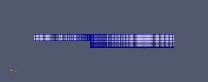
After seeing the first case we are now go for the second case where we apply the grading factor 0.2. This is how we change the grading factor in blockMesh file-
blocks
(
    hex (0 1 2 3 11 12 13 14) (80 5 1) simpleGrading (0.2 5 1)
    hex (3 2 4 5 14 13 15 16) (80 5 1) simpleGrading (0.2 0.2 1)

    hex (2 7 6 4 13 18 17 15) (120 5 1) simpleGrading (5 0.2 1)
    hex (1 8 7 2 12 19 18 13) (120 5 1) simpleGrading (5 5 1)
    hex (10 9 8 1 21 20 19 12) (120 10 1) simpleGrading (5 5 1)
);
Here is the picture after applying the grading factor thus the mesh looks like
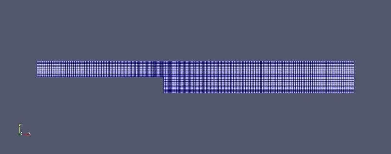
We are now go for the third case where we apply the grading factor 0.5. This is how we change the grading factor in blockMesh file-
blocks
(
    hex (0 1 2 3 11 12 13 14) (80 5 1) simpleGrading (0.5 2 1)
    hex (3 2 4 5 14 13 15 16) (80 5 1) simpleGrading (0.5 0.5 1)

    hex (2 7 6 4 13 18 17 15) (120 5 1) simpleGrading (2 0.5 1)
    hex (1 8 7 2 12 19 18 13) (120 5 1) simpleGrading (2 2 1)
    hex (10 9 8 1 21 20 19 12) (120 10 1) simpleGrading (2 2 1)
);
The mesh looks like-
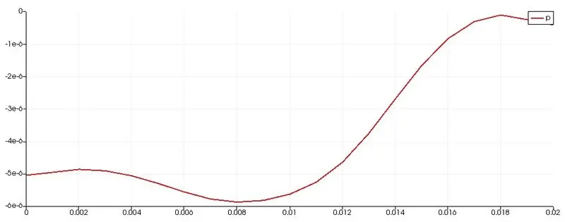
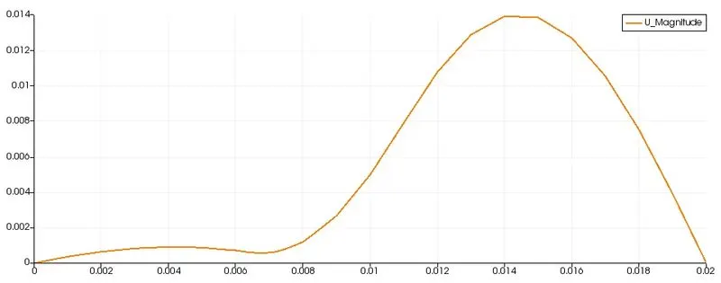
Solution:- Those solution is for the first case when we did not apply any grading factor-
Pressure Plot
Velocity Plot
For better understanding how the flow occurs you can see the video
Those solution is for the second case when we apply 0.2 grading factor-
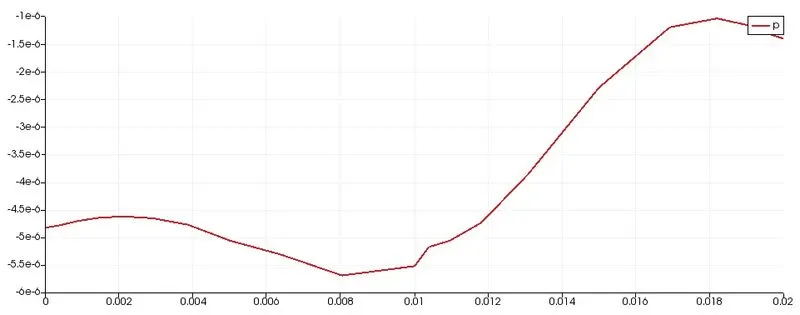
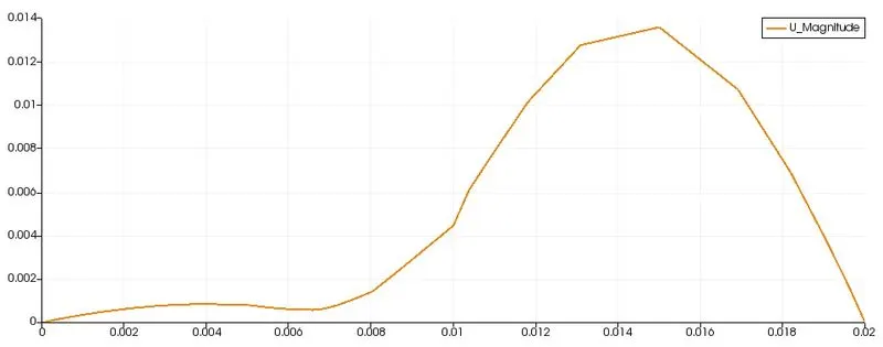
For better understanding how the flow occurs you can see the video
Those solution is for the second case when we apply 0.5 grading factor-
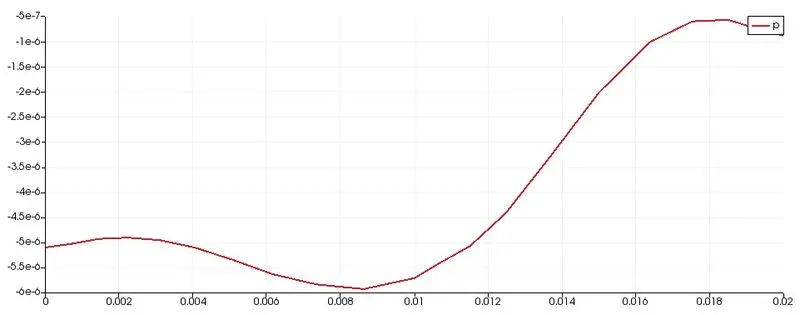
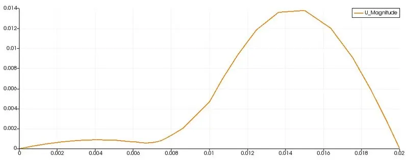
For better understanding how the flow occurs you can see the video
CONCLUSION:-
- If we see the graphs, we do not see more differences but if we see the flow we can understand that with the griding factor we can see a smoother flow.
- With the grading factor, the mesh is more finner and smoother.
- The grading factor helps us to give finer mesh where we need it so the flow is smoother and less time-consuming.
- Because of the grading factor, the simulation time decreases because if we go for creating more cell for better realistic fluid flow it takes more time to converge the solution. But grading factor avoids unnecessary cell in unnecessary part of the geometry that’s why we don’t need to solve equations for those cells we solve only that part where we need more.