Week 9 - Parametric study on Gate valve.
Aim
To perform a parametric study on the gate valve simulation by setting the opening from 10 % to 80%.
Objective
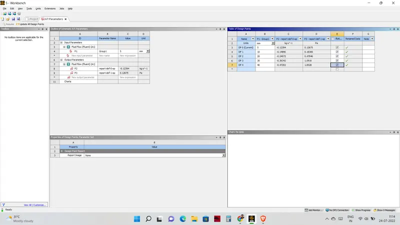
- Obtain the mass flow rates at the outlet for each design point.
- Calculate the flow coefficient and flow factor for each opening and plot the graph.
- Discuss the results of the mass flow rate and flow coefficient.
Introduction
Gate valve
Gate valves are used to shut off the flow of liquids rather than for flow regulation. When fully open, the typical gate valve has no obstruction in the flow path, resulting in very low flow resistance. The size of the open flow path generally varies in a nonlinear manner as the gate is moved. This means that the flow rate does not change evenly with stem travel. Depending on the construction, a partially open gate can vibrate from the fluid flow.
Parameter analysis
A parameter is defined as a numerical or other measurable factor forming one of a set that defines a system or sets of conditions of its operation. Parameters are elements of a system that are useful or critical to identifying a system or evaluating a system’s performance, status, or condition. As an example, parameters of an equation modeling movement could include the mechanics, masses, dimensions and shapes, and densities and viscosities of fluids within the system. A parametric analysis, also known as a sensitivity analysis, is the study of the influence of different geometric or physical parameters or both on the solution of the problem.
Parametric analysis is based on user-defined solving scenarios, producing “unrefined” solutions. These results need to post-processed in order to find the optimal solution or compromise in an overall design.
Flow coefficient`(C_v)`
Gate valves are used to shut off the flow of liquids rather than for flow regulation. When fully open, the typical gate valve has no obstruction in the flow path, resulting in very low flow resistance. The size of the open flow path generally varies in a nonlinear manner as the gate is moved. This means that the flow rate does not change evenly with stem travel. Depending on the construction, a partially open gate can vibrate from the fluid flow.
Mathematical expression `C_v=Qsqrt((SG)/(DeltaP))`
where:
- Q is the rate of flow (expressed in US gallons per minute),
- SG is the specific gravity of the fluid (for water = 1),
- ΔP is the pressure drop across the valve (expressed in psi).
Flow factor(`K_v`)
The metric equivalent of the flow coefficient - Cv - is based on the SI-system and is called the
- Flow Factor - Kv
The flow factor - Kv - is defined as
- the flow of water with temperature ranging 5 - 30 oC through a valve in cubic meters per hour (m3/h) with a pressure drop of 1 bar.
The relationship between Cv and Kv can be expressed as:
`K_v = 0.862 C_v`
Pre-processing
Spaceclaim
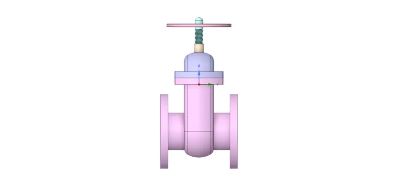
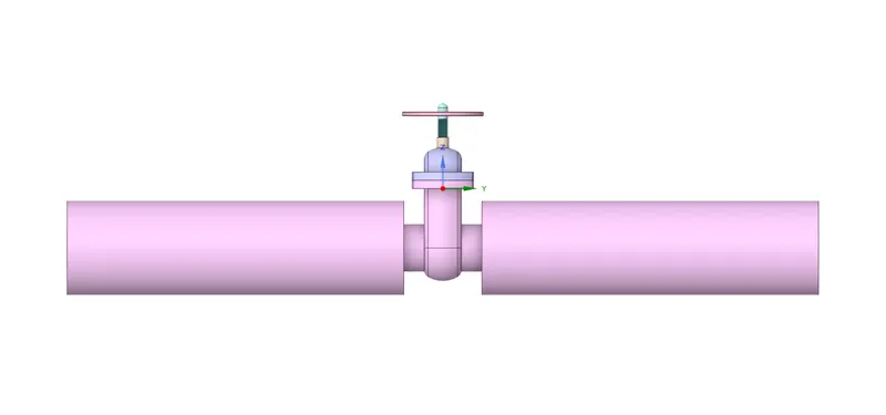
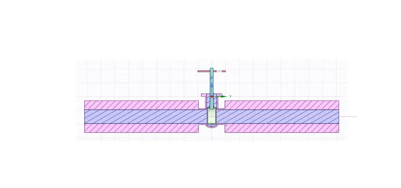
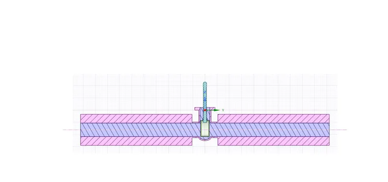
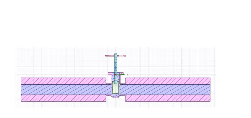
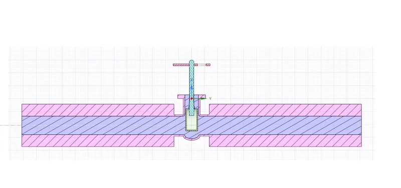
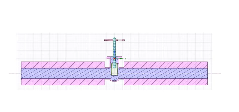
The step file is imported into spaceclaim and the gate disc is raised using the move option and the bottom is pulled to 800mm. The fluid volume is extracted and all the solid components are suppresed for physics. The sides of the valve are included using the update volume body in context.
Meshing
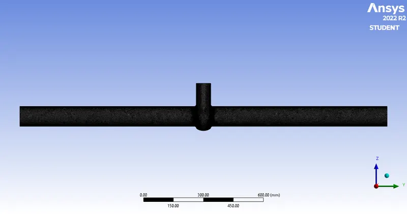
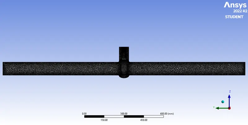
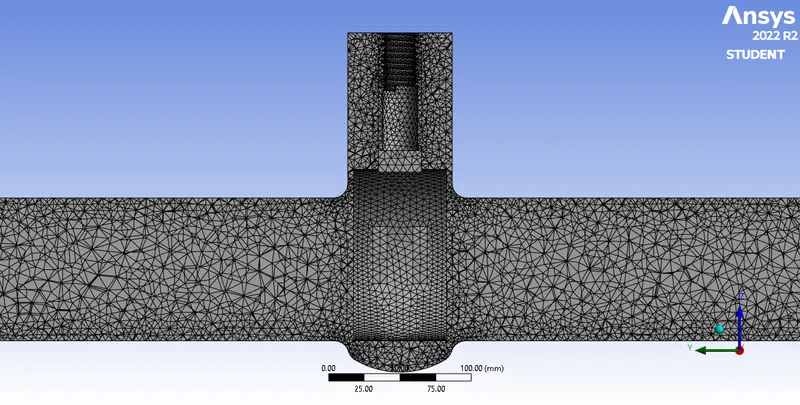
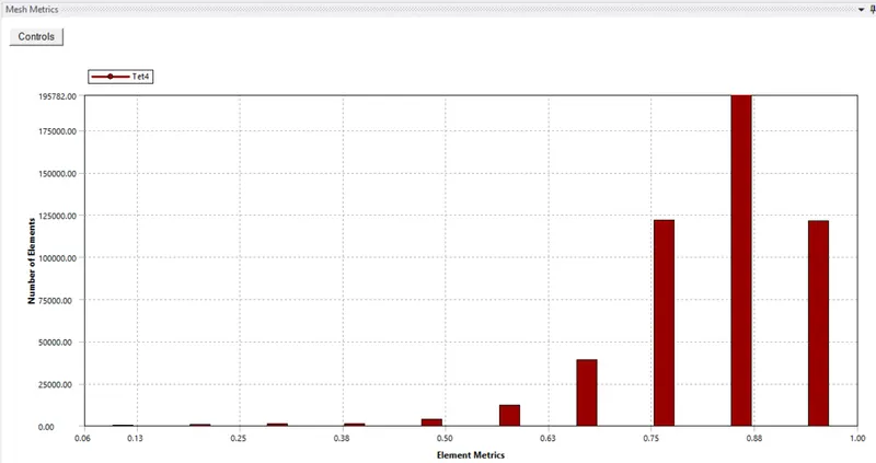
The mesh size is set to 5.5mm and the inlet and the outlet are named.
No of elements : 494131
Grid size : 5.5mm
Solver
Set-up
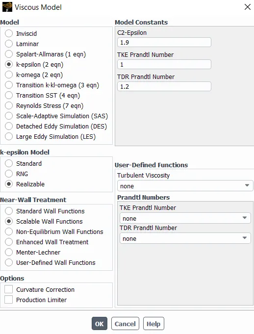
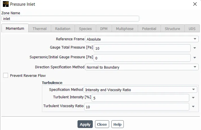
The gravity is set in the Z-direction and the K-`epsi``rarr`realizable`rarr`enhanced wall function is chosen. The volume element is changed to water from the fluent database. Then the inlet is set to pressure-inlet and a pressure of 10bar is set.
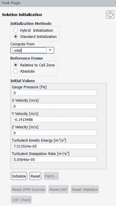
The standard initialization is performed from the inlet.
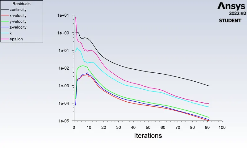
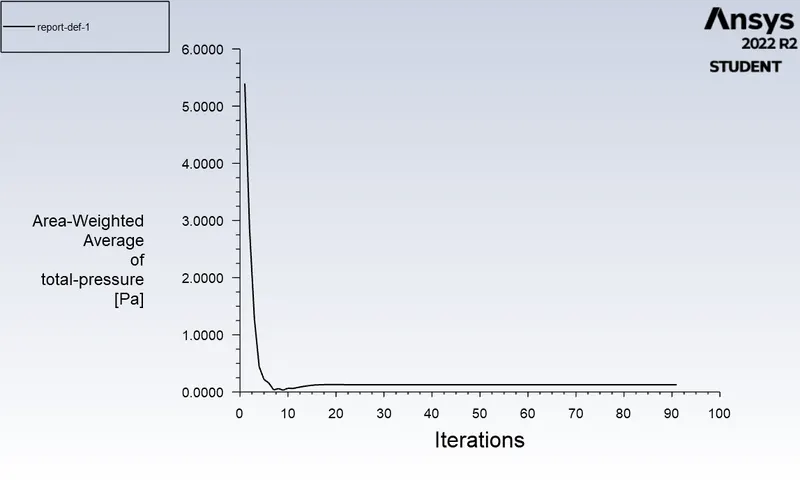
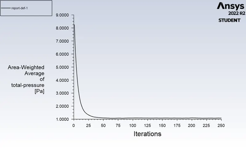
Then the report is generated using the definitions Surface report`rarr`Area weighted average`rarr`pressure and for the massflow rate definitions`rarr`Flux report`rarr`Mass flow rate is used
10%
           Area-Weighted Average                [Pa]
-------------------------------- -------------------
                          outlet            0.126745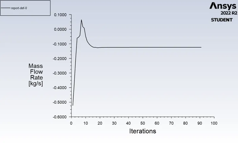
                  Mass Flow Rate              [kg/s]
-------------------------------- -------------------
                          outlet         -0.12394433
`Delta``P=0.0014319945693`psi
20%
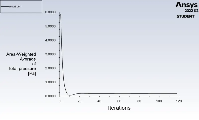
           Area-Weighted Average                [Pa]
-------------------------------- -------------------
                          outlet          0.18702994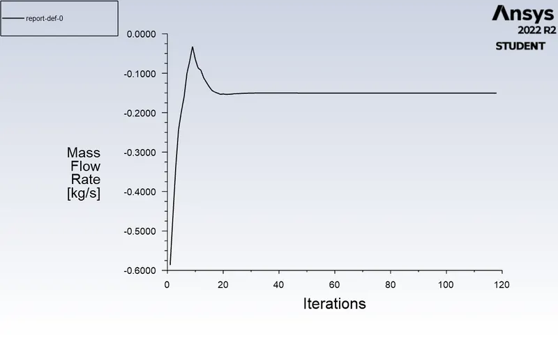
                  Mass Flow Rate              [kg/s]
-------------------------------- -------------------
                          outlet         -0.15037756
`DeltaP=0.001423250977951`
40%
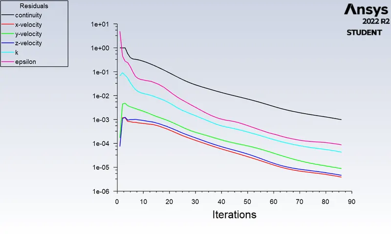
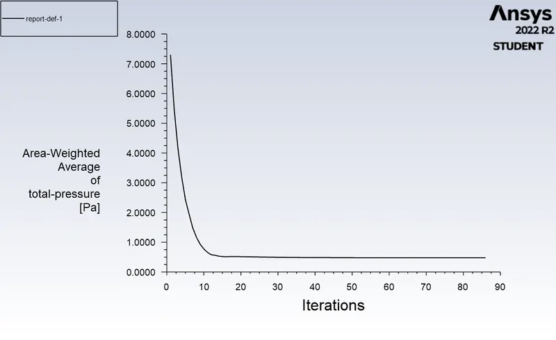
           Area-Weighted Average                [Pa]
-------------------------------- -------------------
                          outlet          0.47766698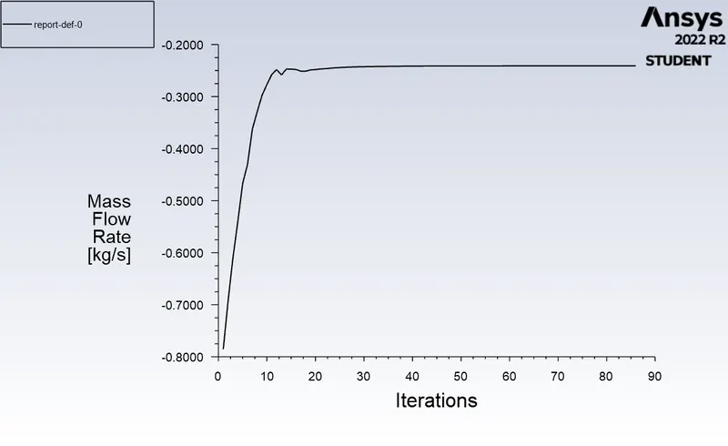
                  Mass Flow Rate              [kg/s]
-------------------------------- -------------------
                          outlet         -0.24081143
`DeltaP=0.00138109723016`
60%
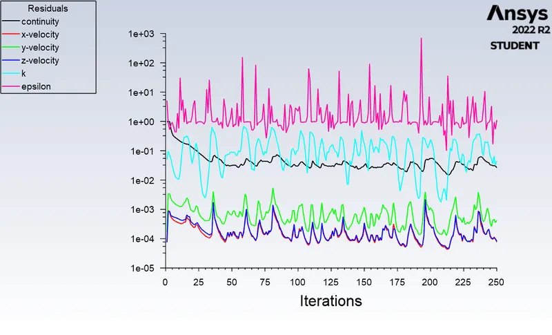
           Area-Weighted Average                [Pa]
-------------------------------- -------------------
                          outlet           1.0866723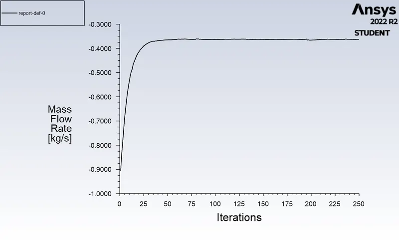
                  Mass Flow Rate              [kg/s]
-------------------------------- -------------------
                          outlet           -0.362468
`DeltaP=0.0012927687838`
80%
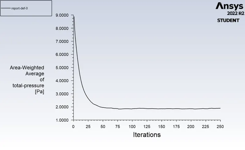
           Area-Weighted Average                [Pa]
-------------------------------- -------------------
                          outlet           1.8953769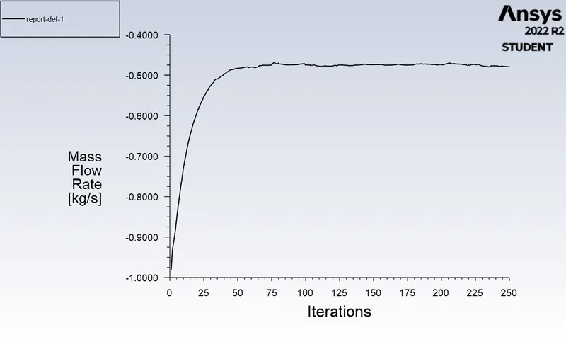
                  Mass Flow Rate              [kg/s]
-------------------------------- -------------------
                          outlet         -0.47923436
`DeltaP=0.00117547619961`
Result
| Disc lift | Mass flow rate(kg/s) | Volume flow rate(g/min) | Flow coefficient(Cv, psi) | Flow Factor(kv) |
| 5mm(10%) | 0.12394433 | 1.96 | 51.794707625919508938296650784447 | 45.32243625 |
| 10mm(20%) | 0.15037756 | 2.38 | 63.08646774055387470713745300854 | 54.5697879 |
| 20mm(40%) | 0.24081143 | 3.82 | 102.79008750524293650546351868411 | 88.9134256875 |
| 30mm(60%) | 0.362468 | 5.75 | 159.92170682867198296074242643799 | 138.332276382 |
| 40mm(80%) | 0.47923436 | 7.60 | 221.66987285806766832766352556309 | 191.744439972 |
The Mass Flow rate increases as the gate disc is increased.
The Pressure also decreases as the disc is lifted.
Also the flow coefficient and fow factor increases with gate lift.
Conclusion
Thus a parametric study on the gate valve simulation by setting the opening from 10 % to 80% has been done.