Week 9 - Parametric study on Gate valve.
gate valve - Definition and theory- gate valve, also known as a sluice valve, is a valve that opens by lifting a barrier (gate) out of the path of the fluid. Gate valves require very little space along the pipe axis and hardly restrict the flow of fluid when the gate is fully opened. The gate faces can be parallel but are most commonly wedge-shaped (in order to be able to apply pressure on the sealing surface).
#) Construction of the gate valve -
Common gate valves are actuated by a threaded stem that connects the actuator (e.g. handwheel or motor) to the gate. They are characterised as having either a rising or a nonrising stem, depending on which end of the stem is threaded. Rising stems are fixed to the gate and rise and lower together as the valve is operated, providing a visual indication of valve position. The actuator is attached to a nut that is rotated around the threaded stem to move it. Nonrising stem valves are fixed to, and rotate with, the actuator, and are threaded into the gate. They may have a pointer threaded onto the stem to indicate valve position, since the gate's motion is concealed inside the valve. Nonrising stems are used where vertical space is limited.
Gate valves may have flanged ends drilled according to pipeline-compatible flange dimensional standards.
Gate valves are typically constructed from cast iron , carbon steel gunmetal ,stainless steel , alloy steel , forged steel
All-metal gate valves are used in ultra-high vacuum chambers to isolate regions of the chamber.
#) Uses of the Gate valve-
1) Wedge gate valve.
2) Plug disk gate valves.
3) knife gate valve.
4) Insider screw gate valve.
5) Rising stem gate valve.
#) Functioning of the gate valve--
The main components of gate valve are body, seat, stem, bonnet, and actuator , the main operation mechanism is simple when the wheel is turned on then it rotates the fluid which is translated into the vertical movement of a gate disc via threads,
They are considered multi-turn valve as it makes more than one 360 degree to fully open and close the valve . when the gate is opened from the path of the flow and when it returns to its close position it seals the bore resulting in a full closure of the valve.
#) Uses of the gate valve -
1) Gate valves are used to shut off the flow of liquid rather than flow regulation when the fully open the typical gate valve has no distortion in the flow path resulting in the low flow resistance. the size of the open flow path generally varies in a nonlinear manner as the gate is removed. This means the flow rate does not change evenly with stem travel . Depending on the construction a partially opened gate valve can vibrate.
2) Gate vaves are used in large diameter pipes since they are less complex to construct than other types of valves in large size.
3) Gate valves without an extra sealing rings on the gate or the seat are used in application where minor leaking of valve is not an issue such as heating circuit or sewer pipes.
#) parametric study of the valve-
One of the best way to get value of the simulation is to do parametric analysis . With very little marginal work a completed model can be parameterized to simulate scenarios limited by the computay=tional time and resources.
As we move forward in the design you can assess the impact that changing certain parameters have on the design. Parametric studies allow you to nominate parameters for evaluations define the parameter ranges specify the design constraints and analyze the result of each parameter variation.
#) A parametric study requires-
1) design objective is set to parametric dimension
2) Parameters nominated for use in the simulation.
3) Parameter ranges identified.
4) Design criteria specified.
5) Various configurations generated.
#) Analysis-
1) Here we will do simulation of the gate valve by opening the valve for 10% to 80% by lifting the gate disc at different level from 10 to 80 %.
2) With the help of the parametric option for lif of gate disc we can parameterized the lift amount and see the different results .
3) Once we study for 10 % of the lift we will parametrize the lift and perform an analysis.
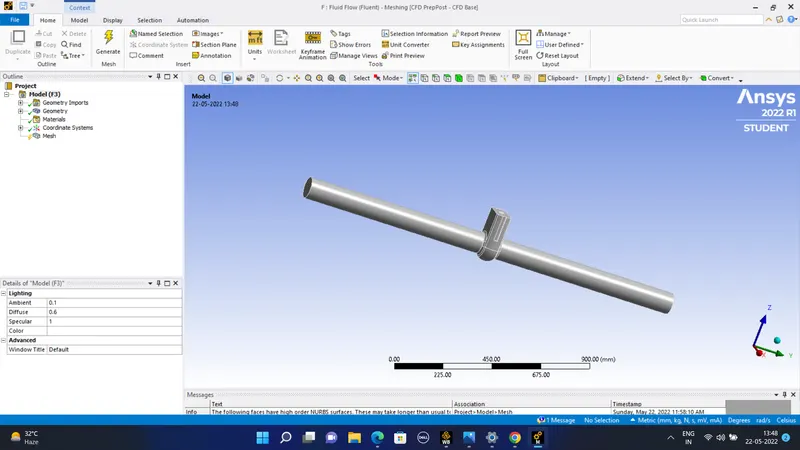
The geometry imported in SpaceClaim is -
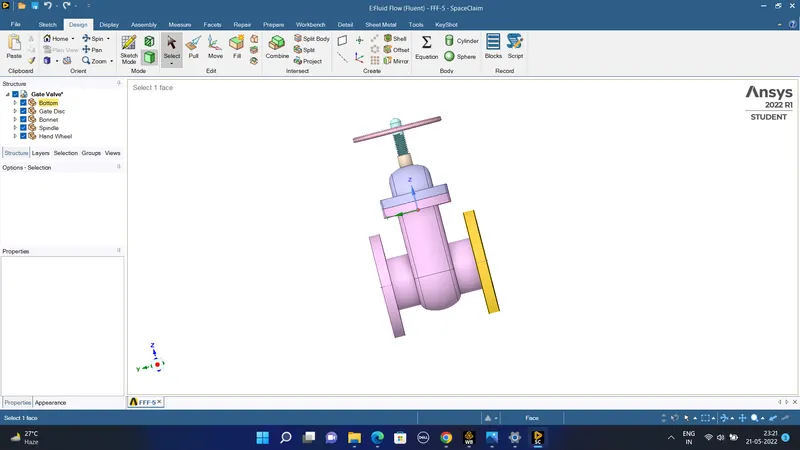
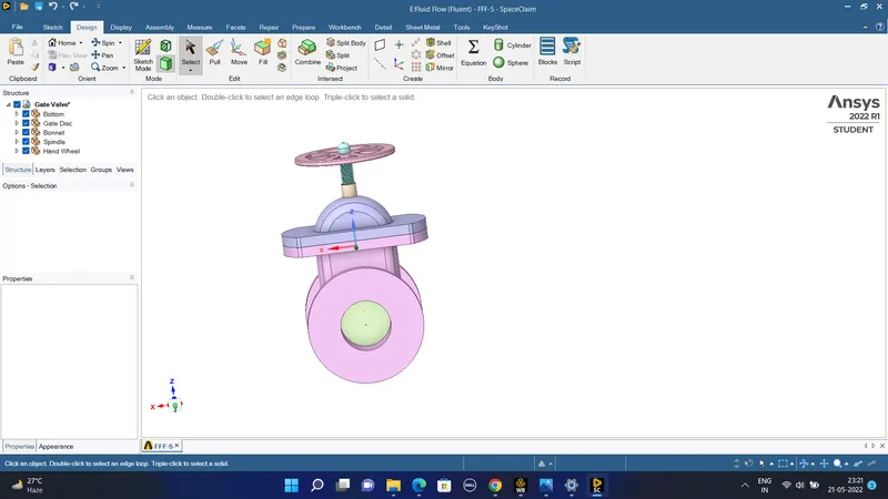
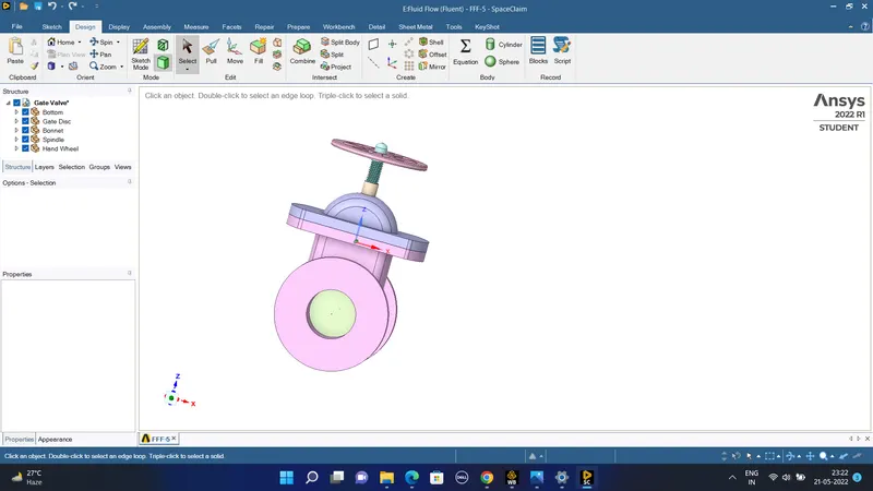
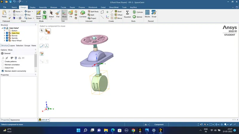
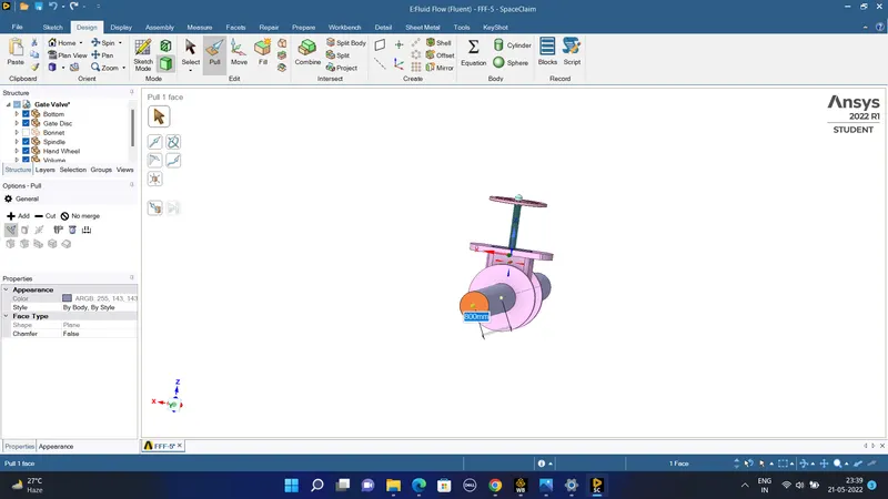
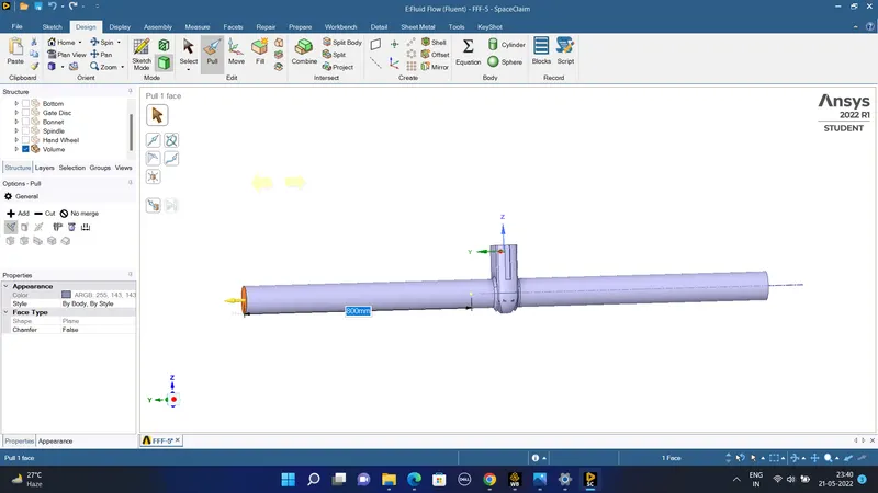
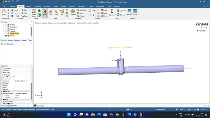
#) To do the parametric study we have to lift the gate valve by a certain distance of 10 mm and increase the distance in a sequential manner from the 10 mm to the 80 mm so that the mass flow rate from the inlet through the gate valve to the exit-
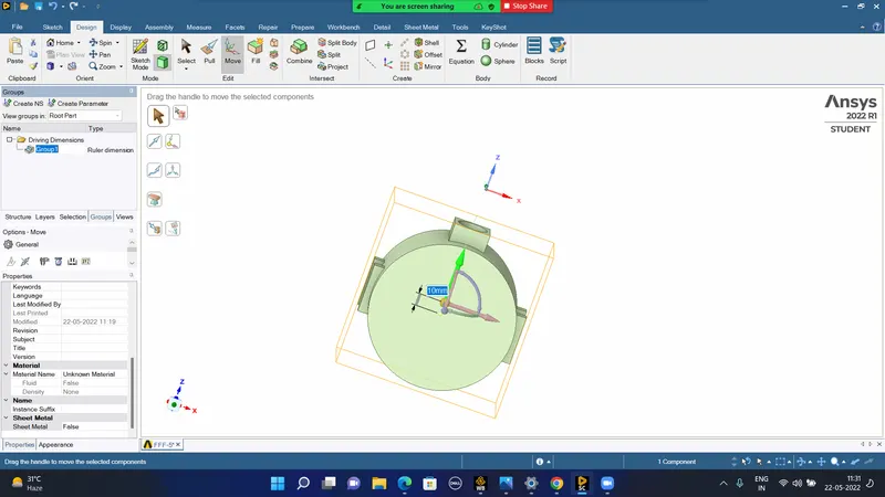
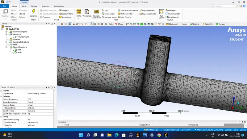
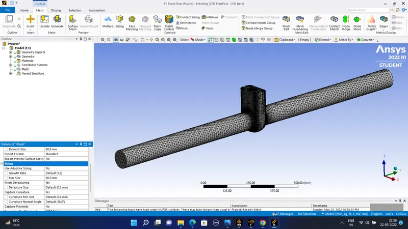
#) Next the fluid volume is meshed using the mesher so that we can solve the velocity distribution in the valve-
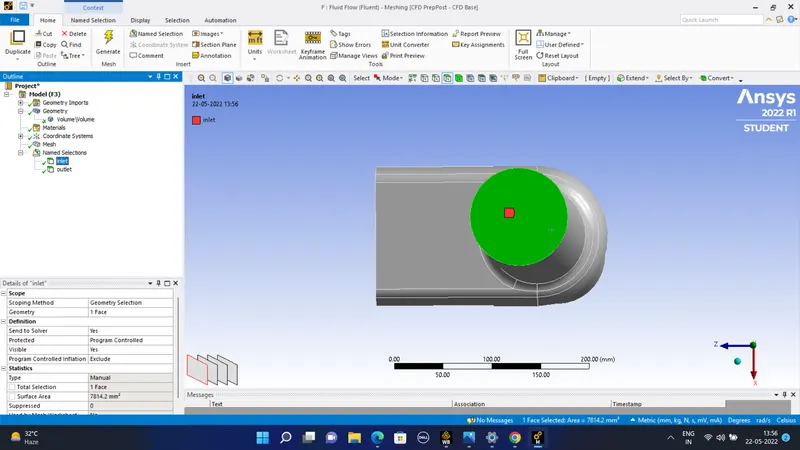
#) The inlet and the outlet bare shown as the following-
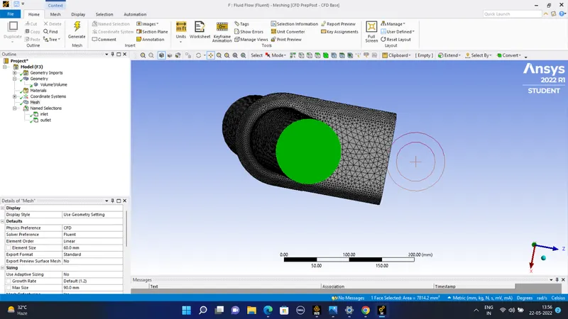
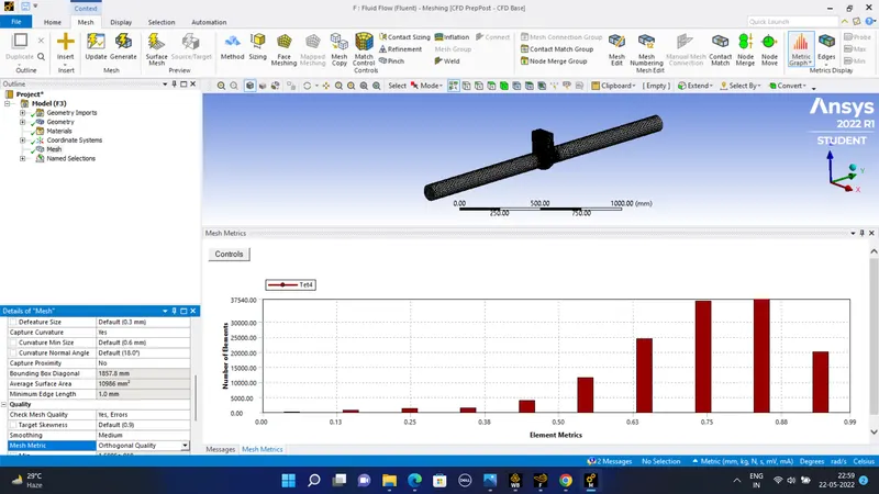
The complete mesh created with the following element size and the mesh metric is as follows-
#) General settings for the solver-
1) Analysis type - Steady type solver.
2) Solver type - Pressure based solver.
3) Gravity - 9.81 m/s^2.
Material specifications-
1) Water - liquid of H2o.
2) Chemical formula- H2o.
3) Density of water = 998.2 kg/m^3.
4) Viscosity- 0.001003 kg/m-s.
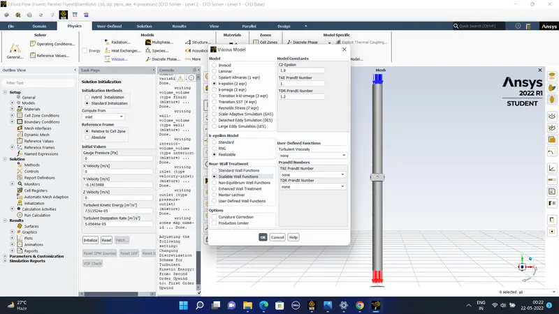
Viscous model - K - epsilon.
K-epsilon - Realizable.
#) Boundary conditions-
Inlet - Type - pressure inlet.
Gauge pressure inlet - 10 pascals.
Outlet - Type- pressure outlet-
Gauge total pressure= 0 pascals.
wall type -wall
stationary wall and shear condition - no slip.
Near wall treatment- Scalable wall function.
We would be using the standard initialization method so that we can directly put the values of the pressure and velocity as the initial value in the iteration so the compute is made from the inlet.
The Reynolds number of the flow is of the Re = 14087.14 which is way more than 2000 . So Reynolds number of more than 2000 is considered turbulent for the pipe flows.
So the flow is turbulent . So the viscous model is k-epsilon model .
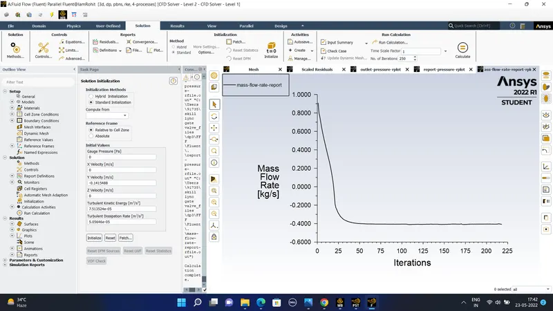
#)The simulation is conducted in the fluent using the following setup as follows- The following mass flow ratre is obtained for the parameter of 60 mm or when the valve is moved up by a distance of 60 mm
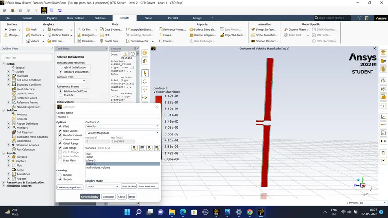
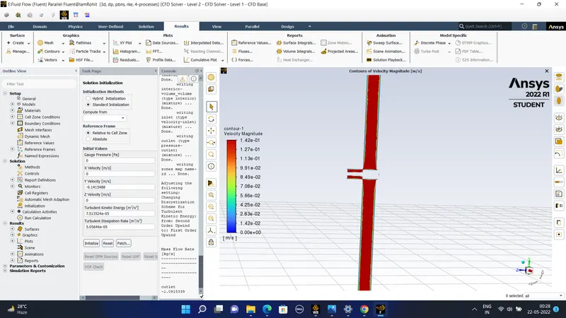
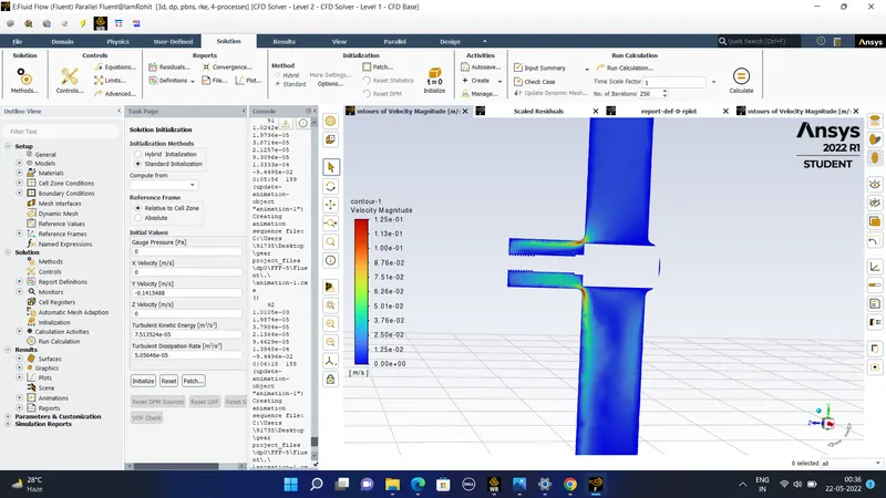
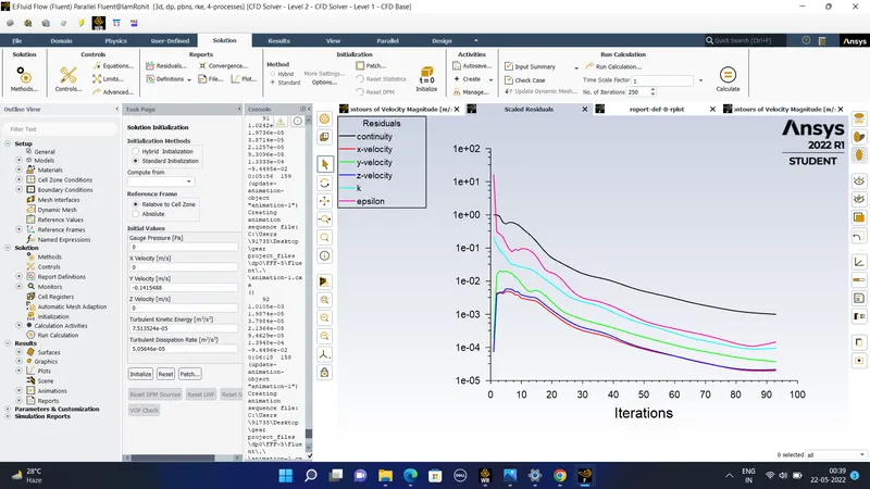
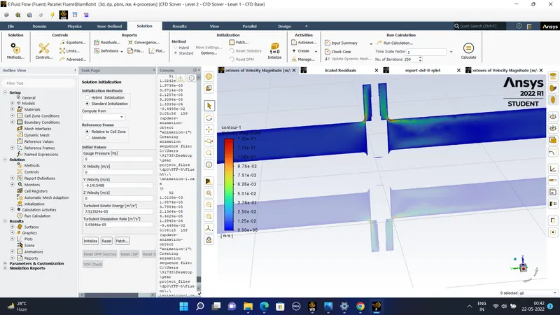
The mass flow rate obtained for this 54 mm case is 0.583 kg/sec.
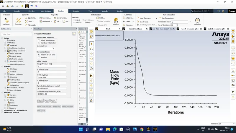
The mass flow rate obtained for the parameter of the 10 mm we obtain the mass flow rate as - 0.1433 kg/sec.
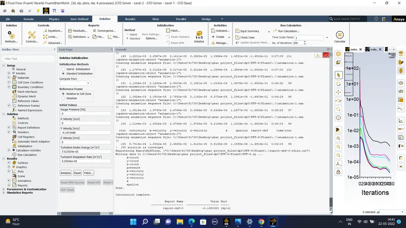
so the mass flow rate is 0.149 kg/sec.
#) For the parameter of the 25 mm we obtained the following plots-
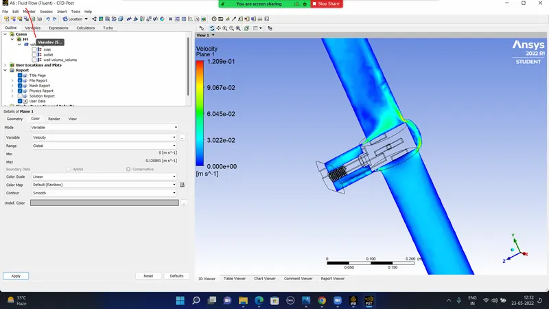
#) For the gate valve at a height of 35 mm above we obtain the following velocity contours and the following mass flow rates as the following-
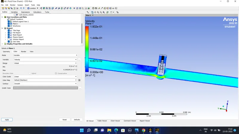
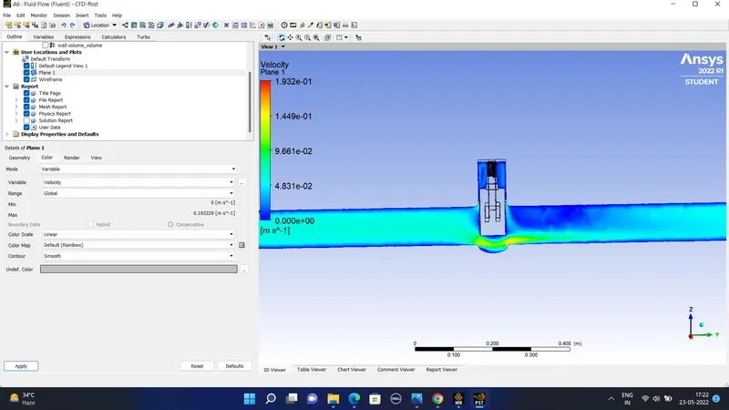
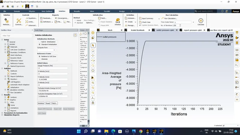
The mass flow rate obtained for 35 mm gate vave is = 0.405 kg/sec and the pressure drop = 8.627 pascals.
The table shows the parameters or the different mass flow rate and the pressure drop obtained as the gate valve is lifted up by different percentages-
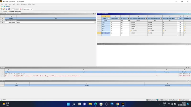
#) As the gate valve is moved from 10 to 80 percent of the valve length we can see that the mass flow rate is increasing and the pressure drop is reducing as the valve is opened more.
The flow coefficient is defined as so the flow coefficient is a relative measure of its efficiency at allowing fluid flow. It decribes the relation between fluid flow and the pressure drop across the orifice. The corresponding flow rate is defined as the following-
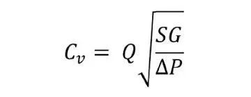
Cv is the flow coefficient q is the flow rate
SG is the specific gravity and deltap is he pressure drop across the orifice.
#) The flow factor is calculated as using the metric units as follows-
Kv = Q*(SG/deltap)^0.5 .
The metric equivalent flow factor (Kv) is calculated using metric units :

where
- Kv is the flow factor (expressed in m3·h−1).
- Q is the flow rate (expressed in cubic metres per hour m3·h−1),
- SG is the specific gravity of the fluid (for water = 1),
- ∆P is the differential pressure across the device (expressed in bar).
Kv can be calculated from Cv using the equation
