Week 9 - Parametric study on Gate valve.
1.Aim:
- Parametric study for Gate valve.
2.Introduction:
- The valve has a disc or a gate. The gate has a transverse motion to the direction of fluid flow. Thus, this arrangement either fully stops or opens the passage of fluid. Gate valve finds its application where it is necessary to handle a constant flow of liquid and at the same time restrict the flow rate of the flow itself to limited values.
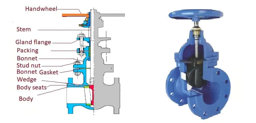
- It is a bi-directional valve. The gate is symmetrical at both ends. Therefore, we can use the inlet as an outlet & vice versa. It allows the fluid flow in both directions.
There are various construction forms of gate valves. Some of the constructive forms are.
- Rising Stem
- Falling Stem
- Knife
- Bulkhead
- Expansion
2.1 Types of Gate valve:
There are two types of gate valves based on the stem design.
- Rising Stem
- Non-rising Stem
2.1.1 Rising Stem:
- In the rising stem valve, the stem rises out on the opening of the valve. We can judge the valve opening or closing from the appearance of the valve stem. The valve stem nut is in the valve bonnet or housing when the valve is fully closed. The stem rotates to lift (gate open) and lower (gate close).
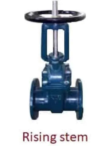
- This type of design is very popular because it is easy to lubricate the valve stem lead screw.
2.1.2 Non Rising Stem:
- Non-rising stem means external stem. We also call it a rotational stem design gate valve. The stem rotates to open and close the gate but, the stem does not move up or down as it rotates.
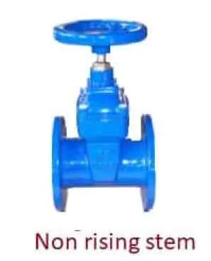
- Upon operating, the stem rotates, and the gate moves in or out. In this way, the non-rising stem moves the gate to open or seal the valve.
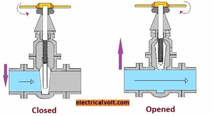
- Non-rising stem valve takes up less space. Therefore, it is most suitable where space is a constraint. The advantage of the non-rising pattern is that the height of the valve does not change. The total height remains the same, so a small control unit can be installed.
- It is suitable for large diameter valves with limited space for the control unit.
- The disadvantage of a non-rising stem valve is that it is impossible to lubricate the valve stem lead screw. Also, the valve stem is in direct contact with the medium. As a result, it can cause erosion and damage to the valve.
2.2 There are two types based on the gate configuration:
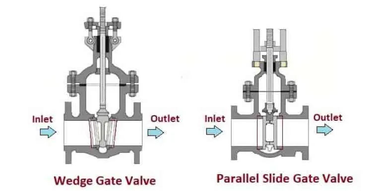
2.2.1 Parallel Slide Gate valve:
- Parallel slide gate valves can be divided into a single and a double gate. In parallel slide construction, as shown in the above figure, the sealing surface is parallel to the vertical centerline. It has an upper and bottom sealing parallel to each other.
2.2.2 Wedge Gate Valve:
- It has a wedge-type construction. It has an up and down gate operation for opening and closing.
- The wedge gate valve can be classified into single, double & flexible gate types. The sealing surface of the gate valve forms an angle with the vertical centerline. Here, the two sealing surfaces form the shape of a wedge.
2.3 Material of contruction:
- Carbon steel, stainless steel, Monel, Duplex, Inconel.
2.4 Advantages:
- High capacity.
- A very efficient hermetic closure.
- They are cheap.
- A very simple operation.
- They are a little resistant to movement.
2.5 Disadvantages:
- They are not efficient in controlling the flow.
- Produce cavitation with low-pressure drop.
- Must be fully open or closed.
- Not to be used for throttling purposes.
2.6 Applications:
- The most common application is for water pipelines, especially cold water.
2.7 Steps involves in Ansys Fluent software:
- Geometry: Construct a two or three dimensional representation of the object to be modelled and tested using the work plane co-ordinate system within Ansys.
- Mesh: At this point understands the makeup of the part. Now define how the modelled system should be broken down into finite pieces.
- Setup: This case setup will be done using Ansys Fluent.
- Solution: Ansys Fluent where run time result visualization is done.
- Results: Post processing of results will be done using CFD post.
3.Procdure:
3.1 Geomentry
1.Open new project, by clicking on Fluid flow(Fluent) in Ansys workbench.
2.Now click on geometry to import Gate valve. It will redirect to Spaceclaim, Ansys geometry model.
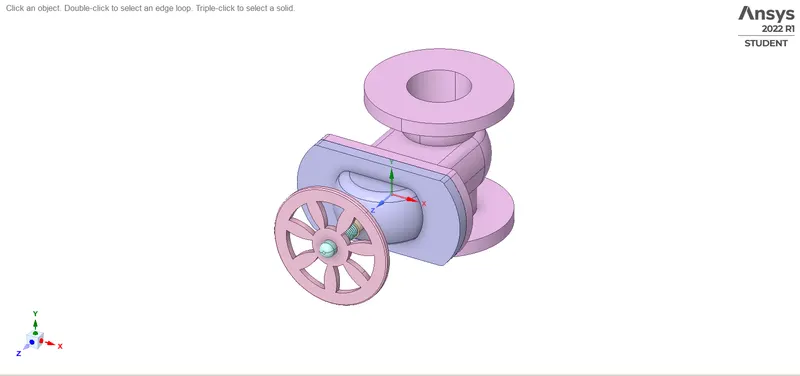
Fig: Gate valve
3. Using pull tool pulling the gate valve inlet and outlet.
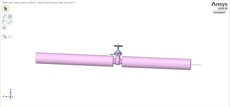
Fig: Pulled Geometry
4. Go to prepare menu and click on volume extract. Switch to edge selection and select three outer edges and click on green check button
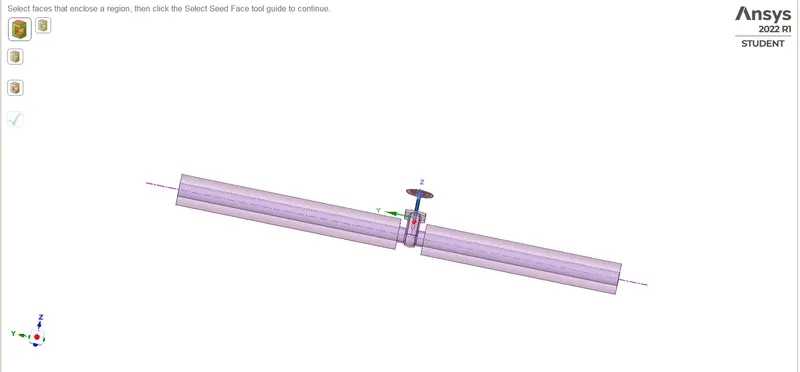
Fig: Extracted model
5. Create cut plane to know the cross section of a body
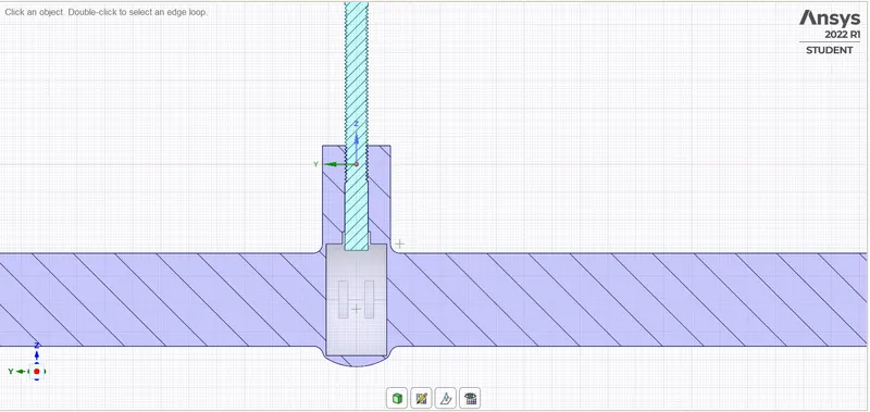
Fig: Geometry with cut plane
6.Exit from Spaceclaim and click on mesh to open mesh menu.
3.2 Mesh
7.Select wall face and press right click of mouse, it will open a menu. Click on option create named selection and write suitable name for Inlet and outlet faces.
8. Now click on mesh option and choose generate mesh. It will generate mesh.
- Mesh Element sizing= 8mm
- Number of Nodes= 52538
- Number of Elements= 255446
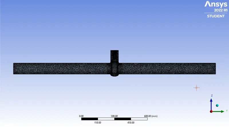
Fig:Generated Mesh
Fig: Futhur zooming of Mesh
3.3 Setup and Solution
9.Exit mesh and open setup. First, Check mesh, it is throwing no error then only we can proceed further. We are going to do pressure based steady state simulation, So choose these options on task page and give the value of gravity of Z direction -9.81.
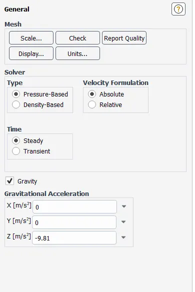
Fig: Task page
10. Go to physics menu and select viscous model. It will open a menu, choose realizable K-epsilon model, Realizable and Scalable Wall functions close it.
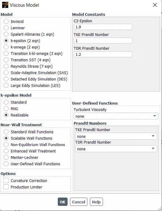
Fig: Viscous model parameters
11.Click on material and choose water as working fluid. check working fluid by clicking on cell zone conditions option, if it Fluid is water then proceed.
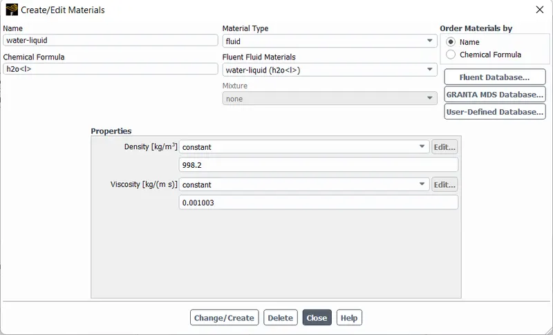
Fig: Fluid Mateials
12.Now go to boundaries option to set boundary conditions. Select inlet x and click on option edit. It will open a menu, Where it is thermal radiation, momentum etc. Put the value of pressure as 10 Pascal.
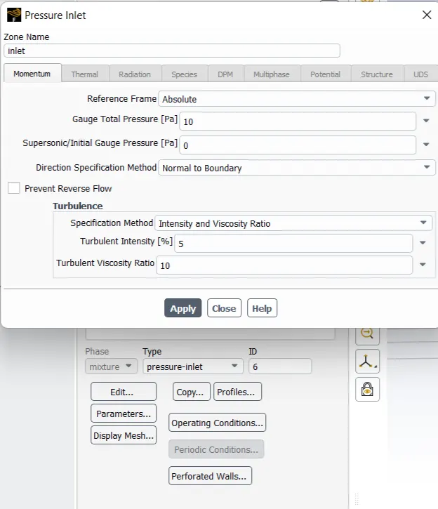
Fig: Boundary condition of inlet
13.Now click on Standard intialization and start compute from inlet for calculate approximate values of velocity and pressure.
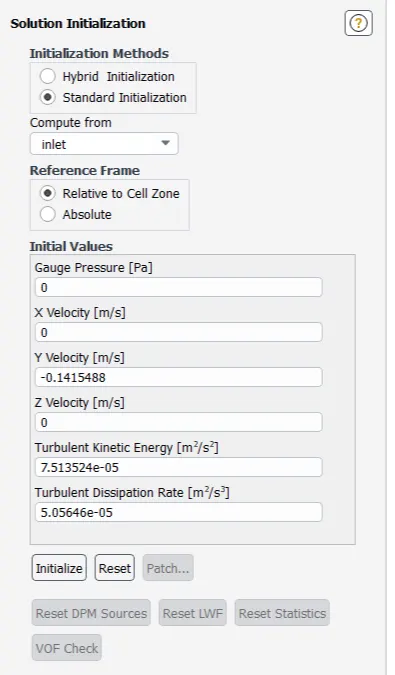
Fig: standard Intialization
14.Change the number of iteration 250(approx) and click on calculate.
15.Exit setup and double click on result to open CFD post. Check boxes to see walls and other parts.
4.Results
4.1 Calculation of stem opening giving in this problem condition:
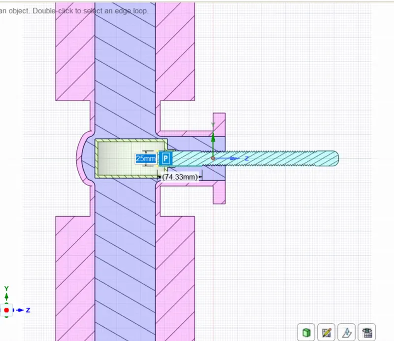
Fig: Dimension of Disc and spendle
- In given condition 10% to 80% of valve opened.
- Length between the Disc side edge and thread side is 74.33
Maximum opening length = 0.8*74.33= 50.9%
4.2 Resulting plots:
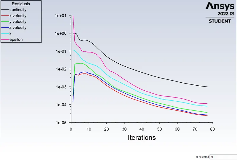
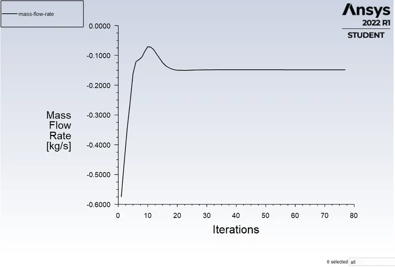
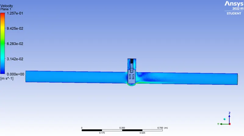
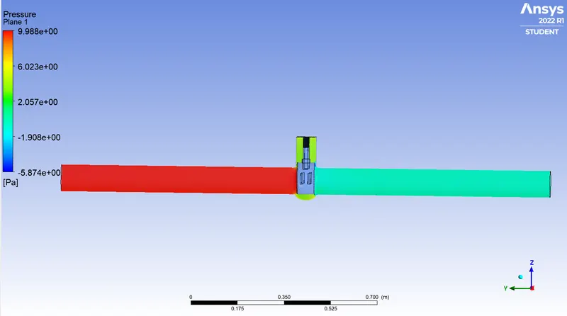
Case:1 Valve opening = 10%
Residual
Mass flow rate
Velocity contour
Pressure contour
Case:2 Valve opening = 20%
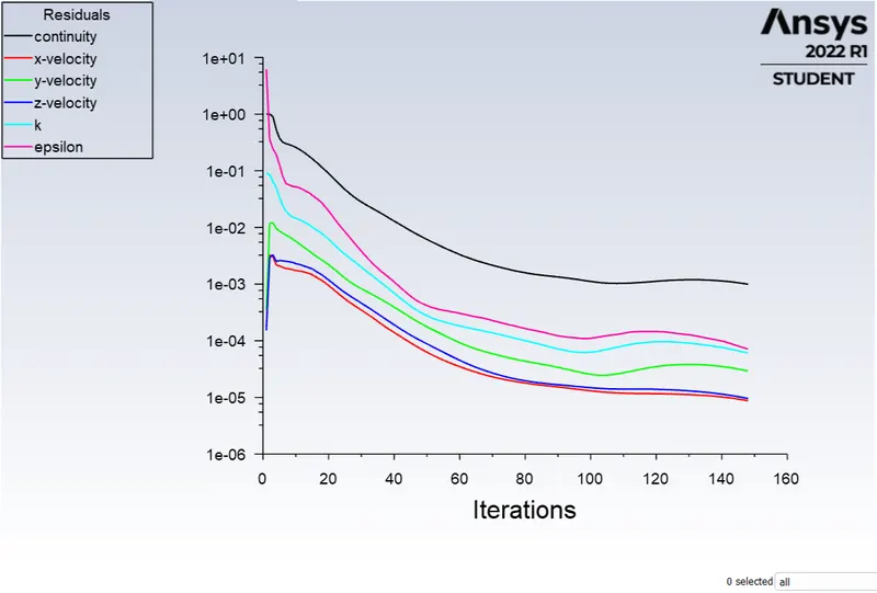
Residual
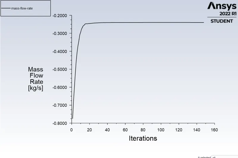
Mass flow rate
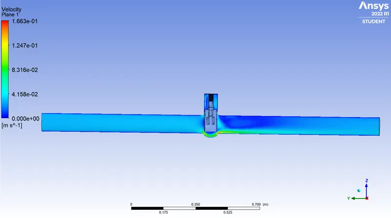
Velocity contour
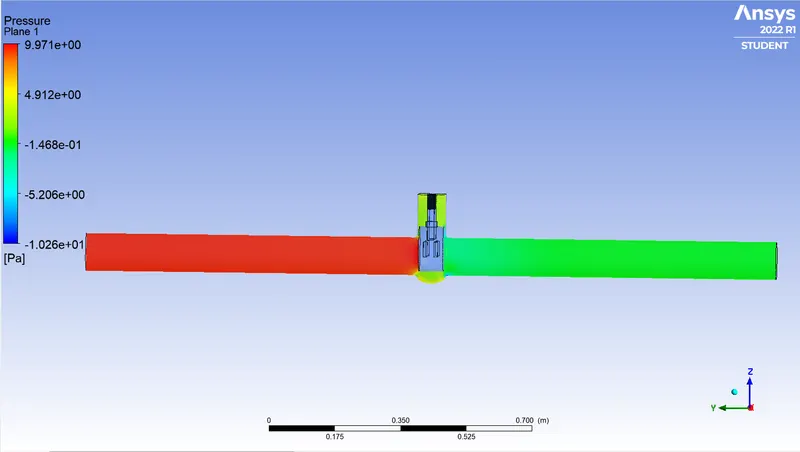
Pressure contour
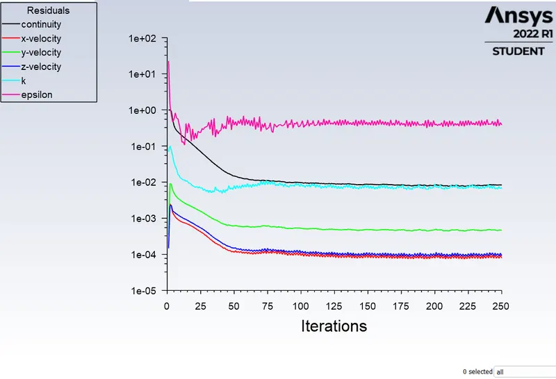
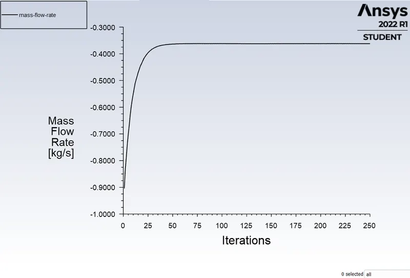
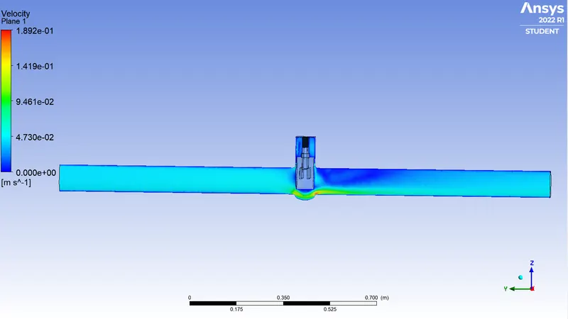
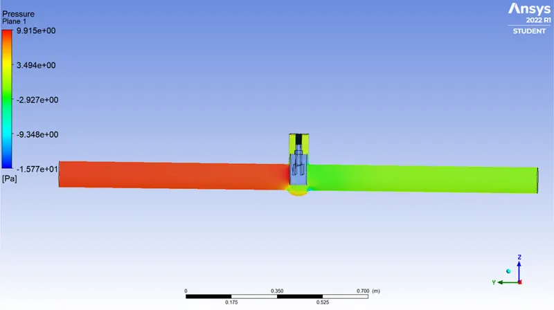
Case:3 Valve opening = 30%
Residual
Mass flow rate
Velocity contour
Pressure contour
Case:4 Valve opening = 40%
Residual
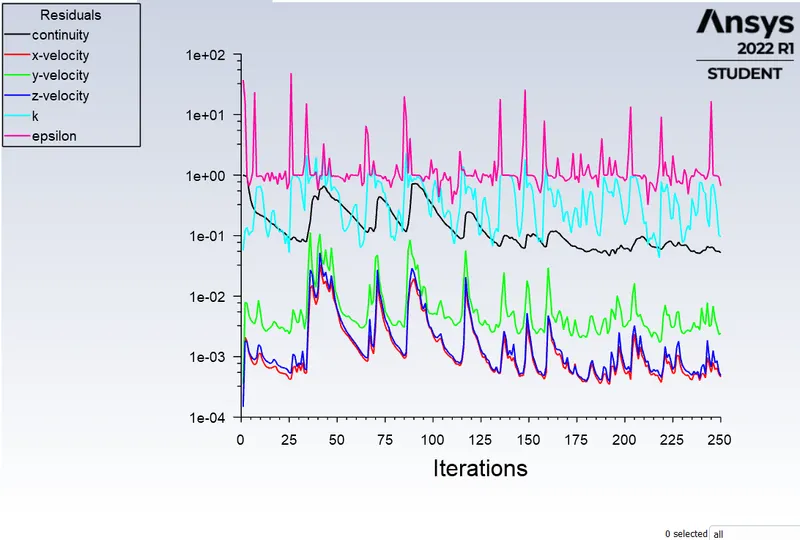
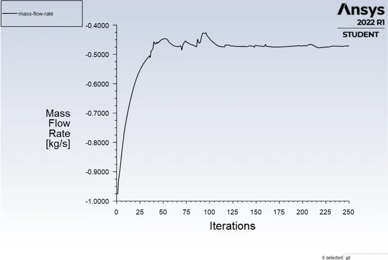
Mass flow rate
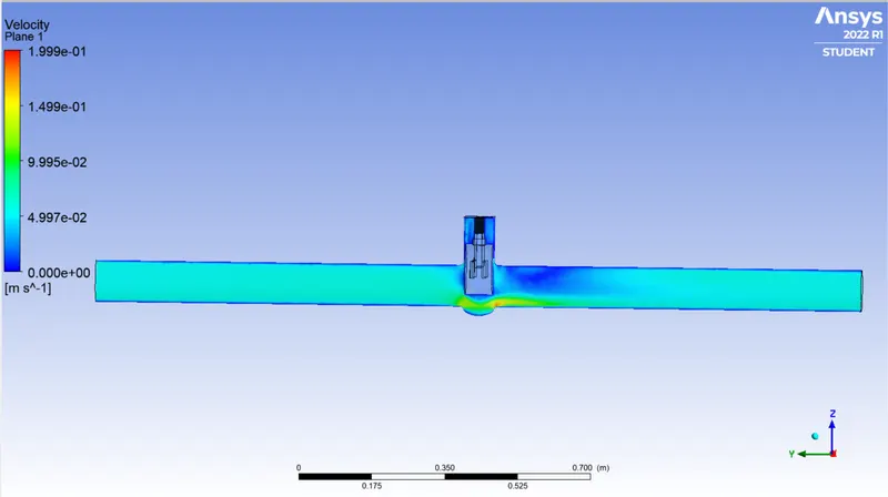
Velocity contour
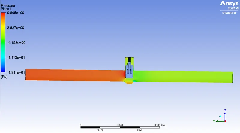
Pressure contour
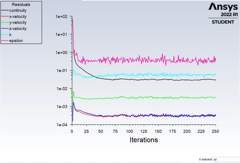
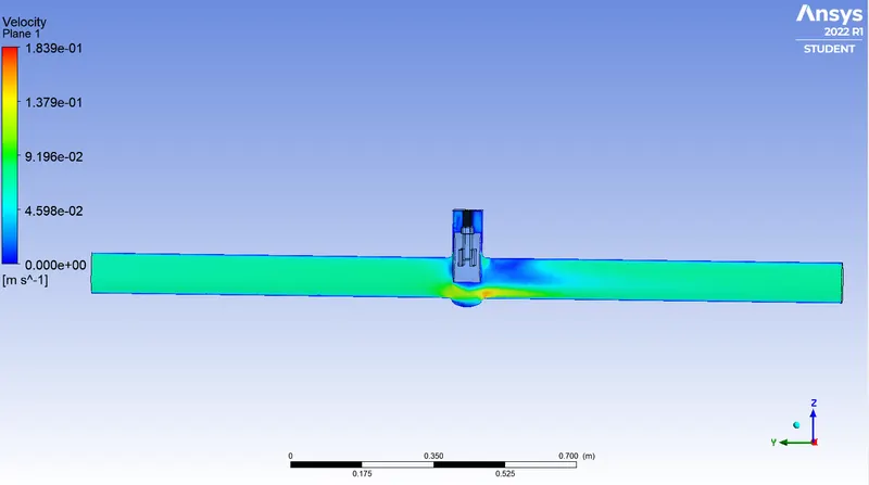
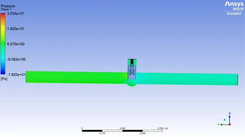
Case 5 valve opening = 50%
Residual
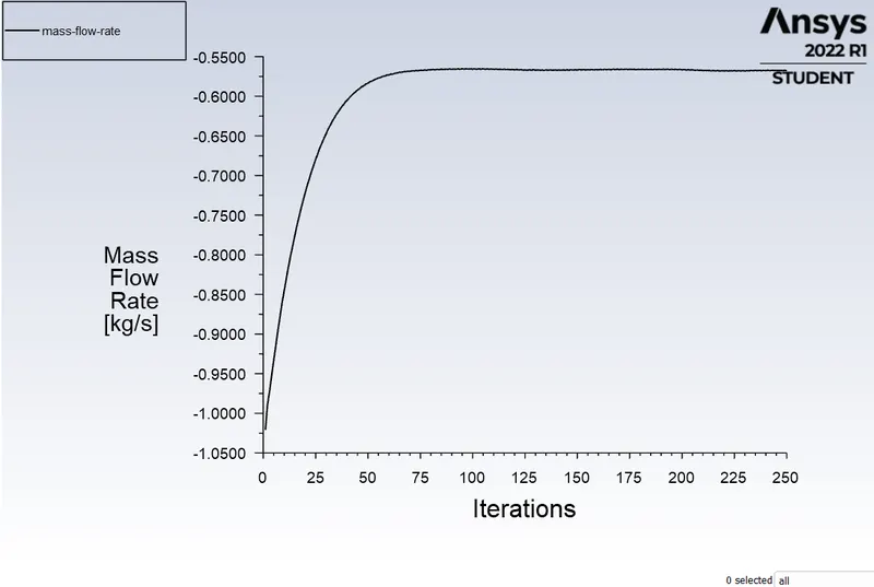
Mass flow rate
Velocity contour
Pressure contour
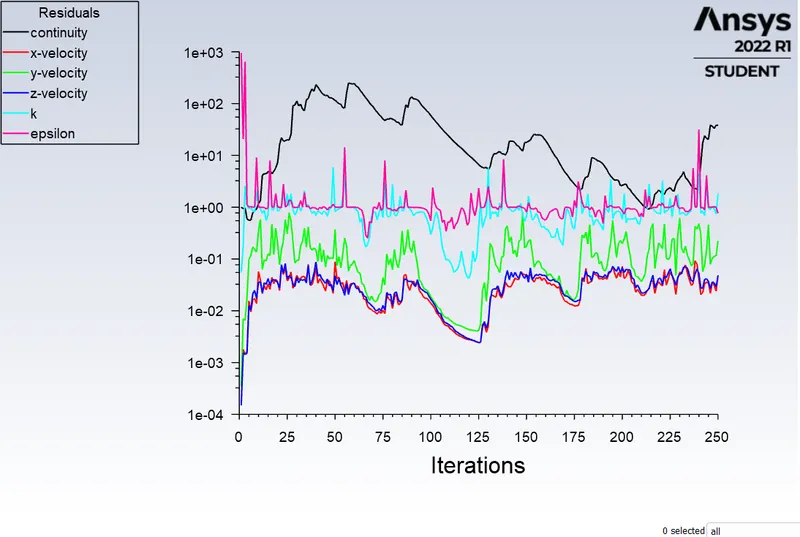
Case:5 Valve opening = 60%
Residual
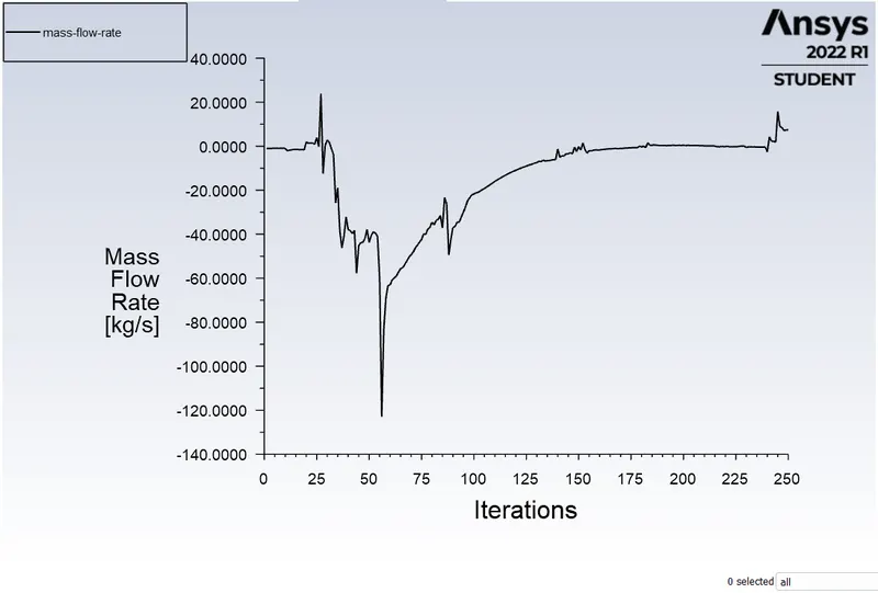
Mass flow rate
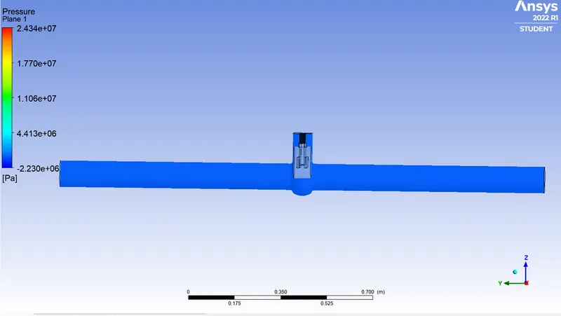
Pressure contour
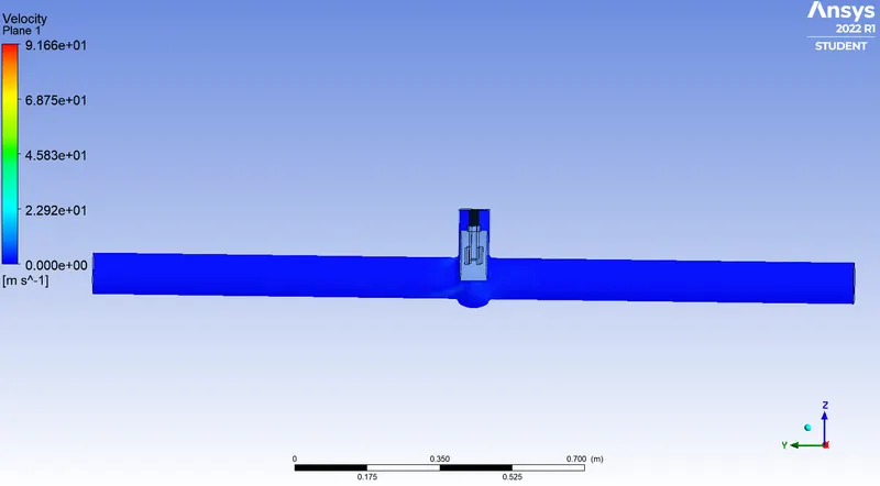
Velocity contour
4.3 Observation about results:
| S.no | Number of iteration | Valve opening percentage(%) | Mass flow rate kg s^-1 |
| 1 | 78 | 10 | -0.1484 |
| 2 | 155 | 20 | -0.24013 |
| 3 | 250 | 30 | -0.36225 |
| 4 | 250 | 40 | -0.4713 |
| 5 | 250 | 50 | -0.56786 |
| 6 | 250 | 60 | 7.3248 |
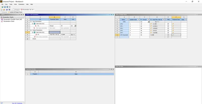
Fig: Parameter
- In above First Five cases are fluid flow across the disc, So that's mass flow rate value is in negative. But the 6th case, Some amount of fluid flow through the Disc because of the distance between Disc inside edge to threated side edge.
5.COnclusion:
- The low lift height refers to the higher pressure drop and thus low flow rate through the valve.
- The negative mass flow is due to the mass exiting the outlet.
- With the help of the parameters the solving time and effort can be reduced drastically.
- Flow factor and coefficient increases as mass flow rate through the valve increases.