Week 9 - Parametric study on Gate valve.
WEEK 9 - PARAMETRIC STUDY ON GATE VALVE
AIM:
- To perform a parametric study on the gate valve simulation by setting the opening from 10 % to 80%.
- Obtain the mass flow rates at the outlet for each design point.
- Calculate the flow coefficient and flow factor for each opening and plot the graph.
- Discuss the results of the mass flow rate and flow coefficient.
- To submit a well-defined report with all the necessary details.
THEORY:
Gate valve:
- A gate valve, or sluice valve, differs from other applications in its family as it operates by raising a barrier up and down to control the fluid path.
- These types of valves require minimal space along a pipe’s axis, and have an extremely low resistance to fluid flow when the barrier is fully lifted allowing full stream power.
- A gate valve design’s main goal is to shut off the flow of fluid.
Types of valves:
- Ball valves.
- Gate valves.
- Globe valves.
Typical gate valve applications:
These types of valves are utilized in a number of different industrial applications, including but not limited to:
- Refinery machinery
- Petrochemical plant machinery
- Low-pressure and high-temperature operations.
Need of analysis:
- Gate valve applications need to be analyzed in the early design process to predict performance in terms of thermal as well as pressure shock.
- In addition to this, pressure drop and the force acting upon the walls of the valve should be evaluated.
PROCEDURE:
1. Spaceclaim:
- Open the spaceclaim and import the gate valve geometry to it.
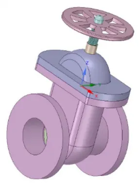
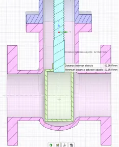
- Now we need to hide the bottm and bottom to extract the fluid volume and to see the gate valve disc which is covered by the bottom part.
- Now we nedd to extract the fluid volume by selecting 3 edges using edge tool.
- Now we need to extend the fluid volume on both sides inlet and outlet using pull tool by giving required dimension.
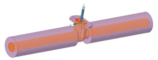
- We also need to suppress all the gate valve parts except the fluid volume.
- Now we need to parametrize, this can be done by going to the design tab and select move and now selecting the move component and selecting the gate disc, there by selecting the right axis we can give the value, according to that the gate disc moves.
- Now we can see in the groups which is adjacent to the structure and there also we can able to edit the value to lift the gate disc.
- Now we need to make sure the spindle is visible and now we need to update the volume body in contact.
- close spaceclaim.
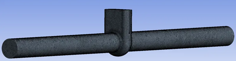
2. Mesh:
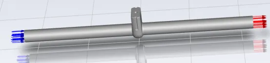
- Firstly we need to name the inlet and outlet.
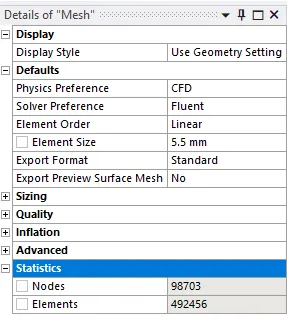
- Now we need to do thee baseline mesh.
- Now we can refine the mesh for the improvement in results.
3. Set-up:
- Open the Set-up
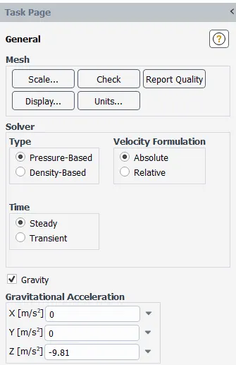
- Enable gravity and give the C.G value in Z-direction, since the geometry is designed in that manner.
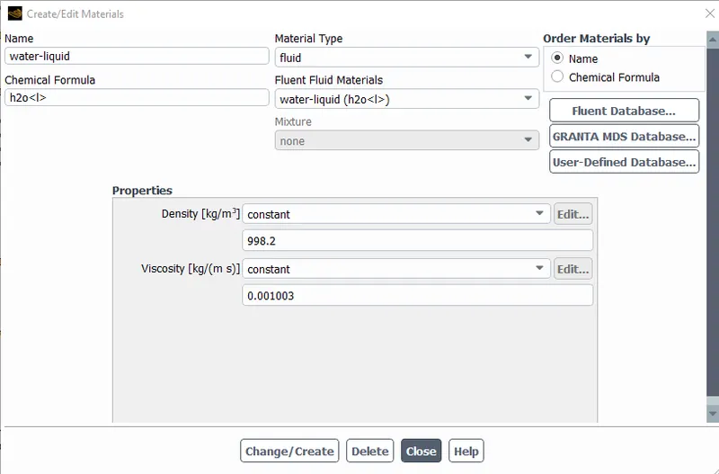
- Now we need to add the material which is water-liquid and we need to delete the default material air if possible.
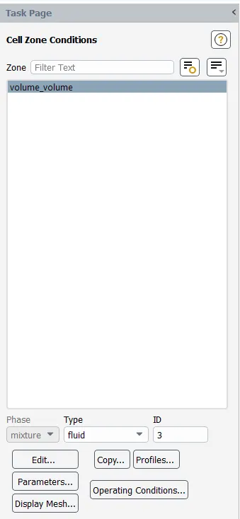
- We need to make sure that the selected material is assigned to our analysis which can be done in cell zones.
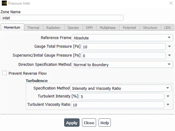
- Now we need to go to boundary conditions and change to the pressure inlet for the inlet and we need to give the gauge total pressure value and other boundary conditions need not to be changed.
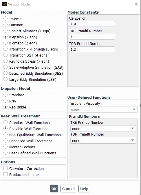
- Now we need to select the viscous model as K-Epsilon, realizable and scalable wall functioins.
- Now we need to create report definition for the mass flow rate and also for pressure at the outlet and we need to print on the console.
- To parametrize, we need to make sure that output parameter is enabled while creating the report definition.
- Initialize by hybrid or standard.
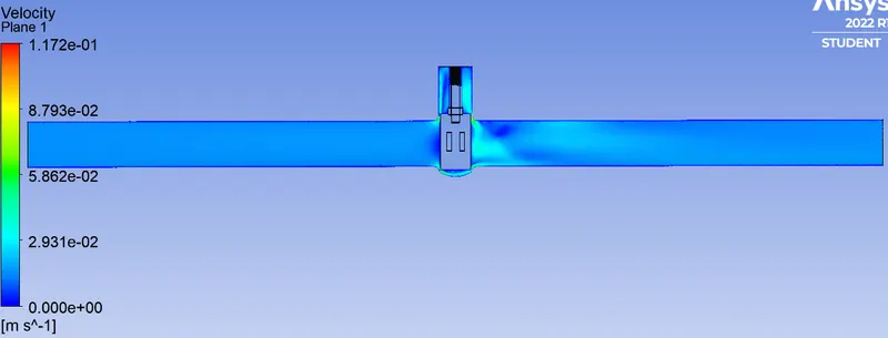
- We need to create the plane and finally velocity contour using the plane which is created.
4. Parameter set:
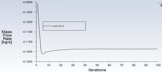
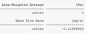
- Here we can see the mass flow rate of the fluid, here we can see the value of mass flow rate for the dimensionn given in the spaceclaim.
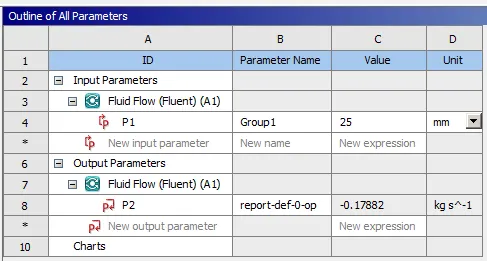
- Here parametrization is already done, so we dont want to go back to spaceclaim and change the value each and every time, here itself we can able to give n number of values for disc lift and we can able to see the mass flow rates correspondingly.
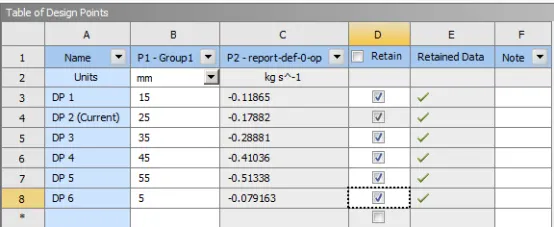
- To see the plots, contours or any results of any case we can do that by assigning that as a current case.
Results:
5 mm:
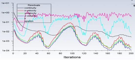
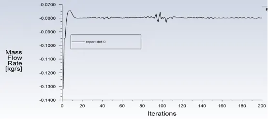
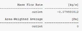
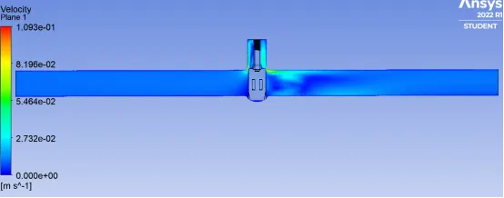
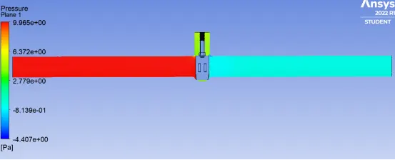
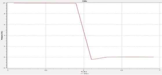
15 mm:
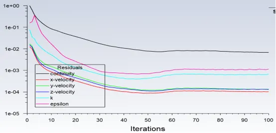
25 mm:
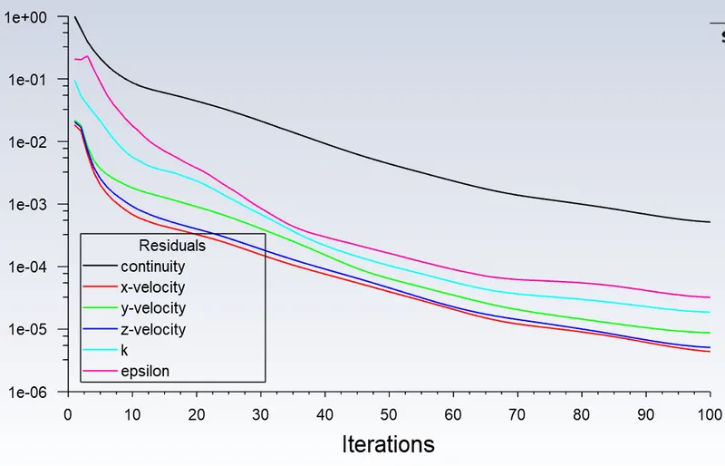
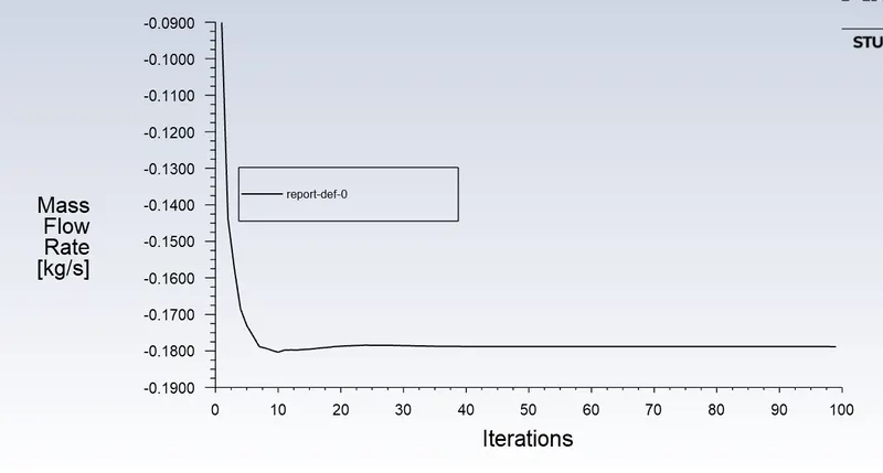
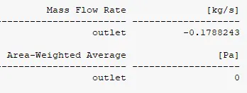
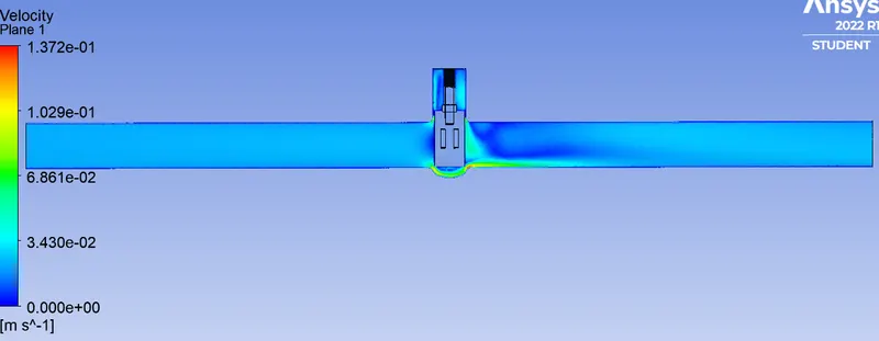
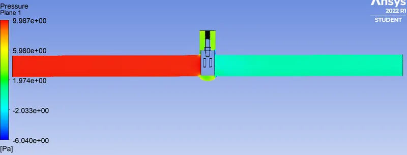
35 mm:
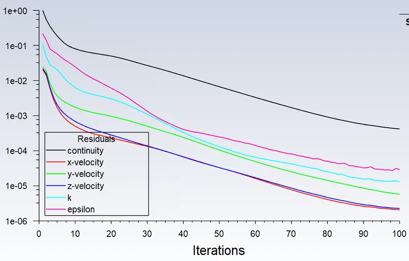
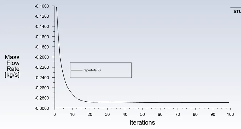
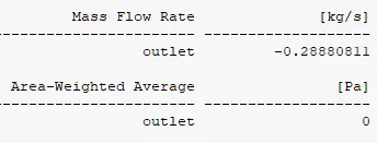
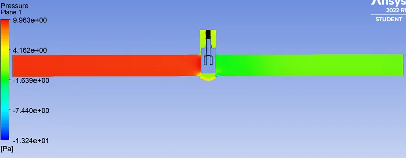
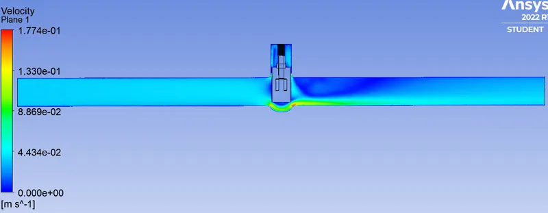
45 mm:

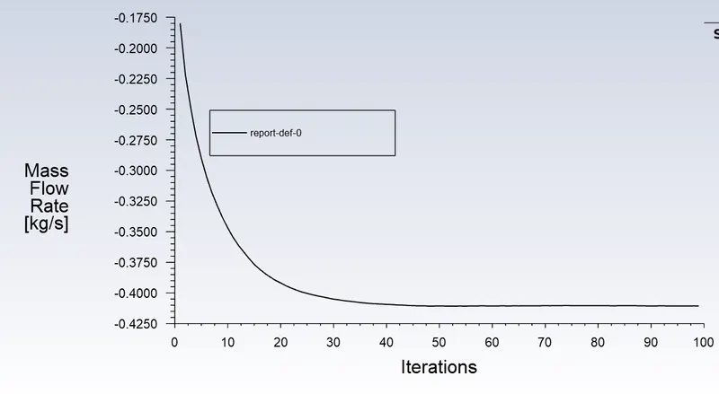
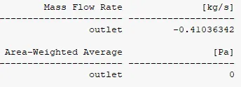
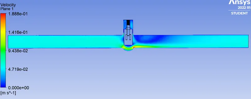
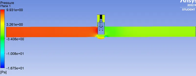
Conclusion:
Flow co-efficient:
`F_c = Q * sqrt (S_g/(Delta P))`
where,
`F_c` = Flow co-efficient
`Q` = Rate of flow
`S_g` = Specific gravity of fluid (water = 1)
`Delta P` = Pressure drop across the valve.
Flow factor:
`F_f = 0.865 * F_c`
Tabulation:
| S.no | Disc lift (m) |
Mass flow rate (Kg/s) |
Inlet pressure (pa) | Outlet pressure (pa) | Pressure drop (pa) | Pressure drop (PSI) | Flow rate (Q) (m^3/s) |
Flow rate (Q) (gallons /min) |
Flow co-efficient | Flow factor |
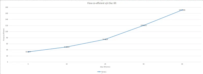
| 1 | 5 | 0.079981 | 10 | 0 | 10 | 0.00145038 | 7.9981e-5 | 1.2677246 | 33.2877 | 28.7938 |
| 2 | 15 | 0.11865 | 10 | 0 | 10 | 0.00145038 | 1.1865e-4 | 1.8806408 | 49.3815 | 42.7149 |
| 3 | 25 | 0.17882 | 10 | 0 | 10 | 0.00145038 | 1.7882e-4 | 2.8343547 | 74.4239 | 64.3766 |
| 4 | 35 | 0.28881 | 10 | 0 | 10 | 0.00145038 | 2.8881e-4 | 4.5777318 | 120.2011 | 103.973 |
| 5 | 45 | 0.41036 | 10 | 0 | 10 | 0.00145038 | 4.1036e-4 | 6.5043386 | 170.7896 | 147.733 |
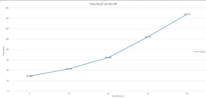
- The mass flow rate increases whenever the gate valve disc is pushed higher and higher, which means volume of the fluid increases at the outlet.
- Flow co-efficient, flow factor and flow rate increases when the mass flow rate increases.
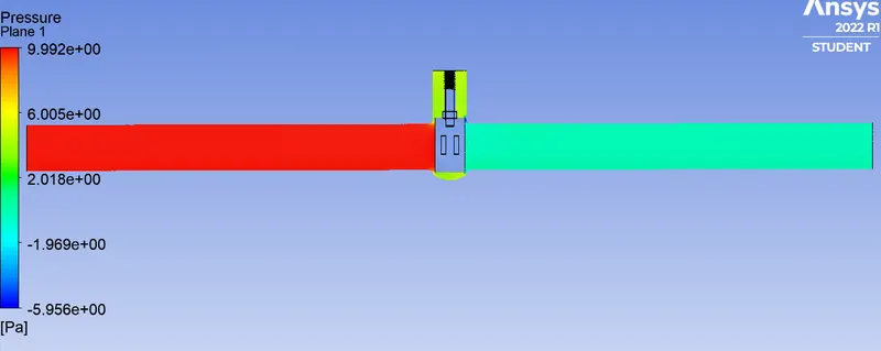
- When the disc is pushed higher and higher, the pressure drop decreases due to increase in outlet pressure, but in my case outlet pressure is zero for all the cases.
- The flow coefficient of a device is a relative measure of its efficiency at allowing fluid flow. It describes the relationship between the pressure drop across an orifice valve or other assembly and the corresponding flow rate.
- High flow coefficient of a device such as restriction orifice or a control valve indicates low resistance to the passage of flow. Similarly low coefficient indicates higher resistance to the passage of flow and high pressure drop for a given flow.