Week 9 - Parametric study on Gate valve.
PARAMETRIC STUDY ON GATE VALVE
A gate valve controls the media’s flow by lifting the gate (open) and lowering the gate (closed). A gate valves distinct feature is the straight-through unobstructed passageway, which induces minimal pressure loss over the valve. Gate valves are used for applications where valve operation is infrequent, such as isolating valves. Gate valves should be used either fully open or fully closed, not to regulate flow.
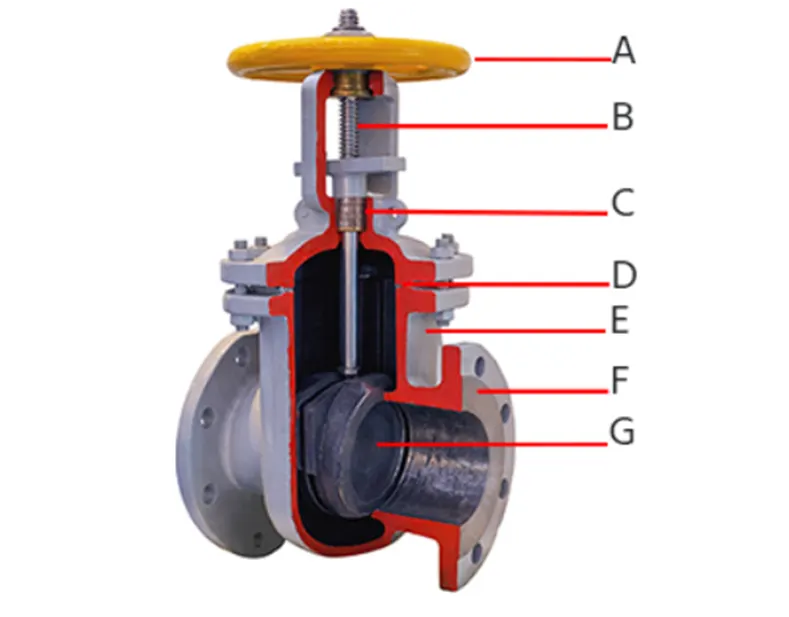
A gate valves main components as seen in figure 1 are the handwheel (A), spindle (B), gasket (C), bonnet (D), valve body (E), flange (F), and gate (G).
For a gate valve, the relationship between the gates vertical travel and the flow rate is nonlinear, with the highest changes occurring near shutoff. When used to regulate flow, the relatively high velocity of the flow at partial opening results in gate and seat wear, which along with possible vibrations of the gate, shortens the valves service life.
OBJECTIVES
- For this project, a parametric study on the Gate valve is done in Ansys Fluent.
- This involves varying the valve opening from 10% to 80% of pipe diameter or valve width. The mass flow rate increases as the valve opening increases.
- The flow coefficient, which is a measure of efficiency of a valve to allow flow through it is calculated for every valve opening.
SOLVING & MODELLING APPROACH
- The conditions of flow through a gate valve are mostly incompressible. In this case the fluid is water.
- The flow regime is assumed to be turbulent. So appropriate turbulent models are choosen.
- The flow is simulated for pressure inlet & pressure outlet boundary conditions.
- The fluid volume is chosen suitably as the control volume for analysis.
GEOMETRY & MESH
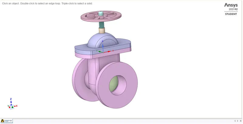
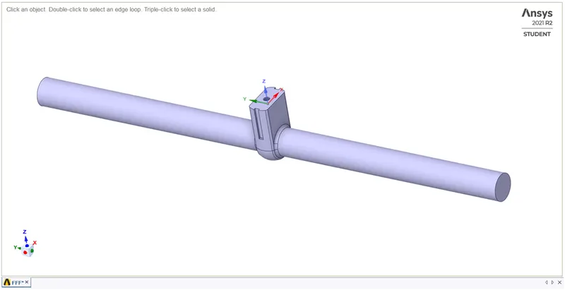
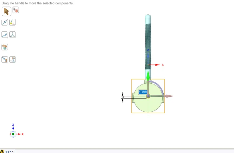
The geometry shown is similar to discussed in the previous section. Using the ‘Move’ option in SpaceClaim, the gate disc is moved up by some distance to open the valve. Initially this opening is small. The fluid volume is extracted by extending the flange in both the directions. Except the fluid volume, other components of the valve are suppressed for physics which ensures the equations are only solved for the fluid volume.
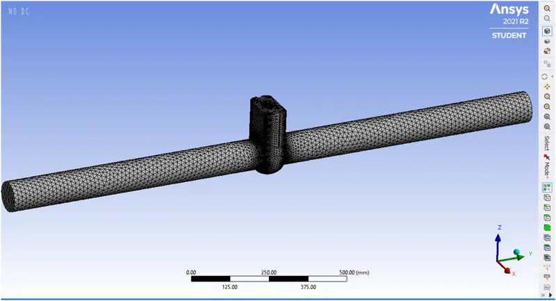
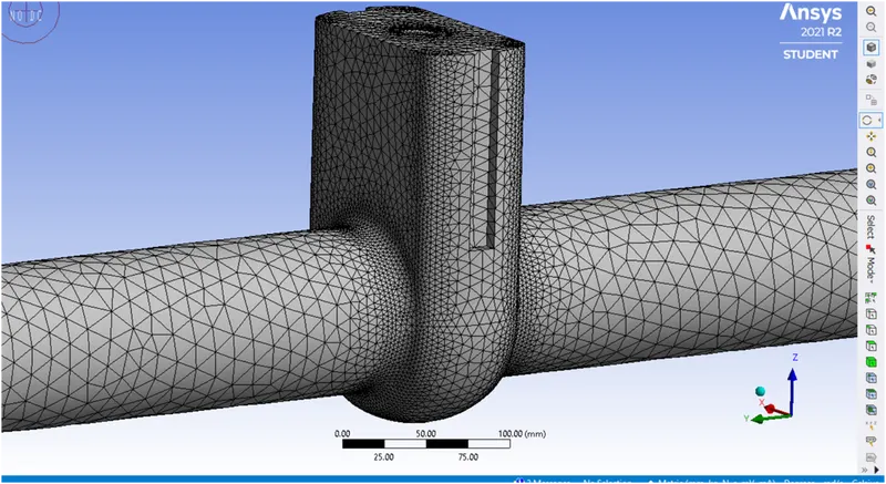
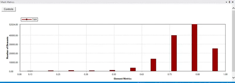
A default mesh is created with element size 50 mm. The element quality is also maintained within limits.
SOLVER REQUIREMENTS
The k-epsilon realizable with scalable wall treatment is employed to simulate turbulence.
The coupled method is enabled as the problem has pressure boundary conditions.
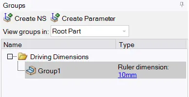
The valve opening is parametrized as shown below. In the Fluent solver the mass flow rate is parametrized as well. The values for valve opening are taken as inputs in the ‘parameters’tab. Ansys Fluent automatically updates the fluid volume and solves the equations and calculates the mass flow rate for each ‘Design Point’.
RESULTS
The following table shows the results after the simulation is ran for all the design points.
The 2nd column is valve opening in mm and the third column is mass flow rate in kg/s.
| Name | P1 - Group1 [mm] | P2 - report-def-0-op [kg s^-1] |
| DP 4 | 7.5 | -0.13350567 |
| DP 5 | 15 | -0.18709668 |
| DP 6 | 22.5 | -0.26739175 |
| DP 7 | 30 | -0.50408011 |
| DP 8 | 37.5 | -0.44594294 |
| DP 9 | 45 | -0.51506734 |
| DP 10 | 52.5 | -0.58025168 |
| DP 11 | 60 | -0.63170415 |
The flow factor is calculated from the formula defined below,
Kv = `Q*sqrt((SG)/(DeltaP))`
Kv is expressed in m^3/h
Q is the flow rate in m^3/h
SG is the specific gravity of fluid (For water SG = 1)
`DeltaP` is the pressure differential expressed in bar
The flow coefficient expressed in Gallons/minute is calculated from Kv by the correlation
Kv = 0.865*Cv
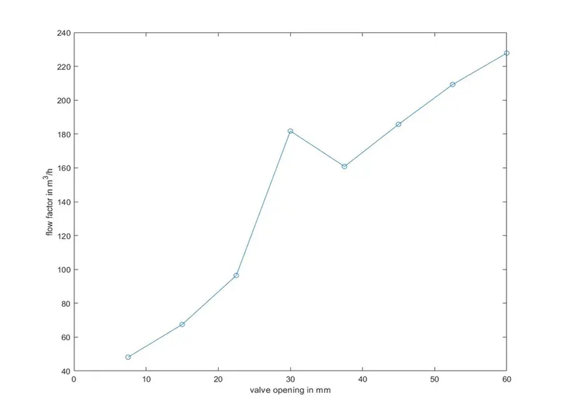
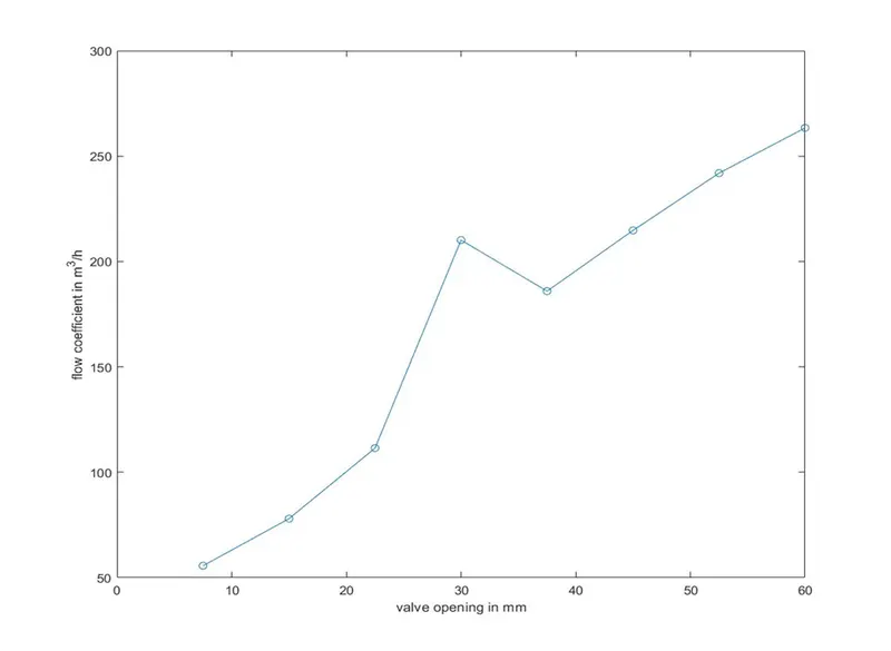
The flow factor and flow coefficient both are determined for each valve opening and the results are plotted in MATLAB, are as follows,
Flow factor Flow coefficient
Inferences/conclusions
From the graphs it is clear that the mass flow rate increases with increase in valve opening. The relationship between the valve opening and the flow coefficient is fairly linear.
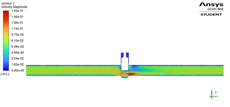
The flow attains maximum velocity at the valve exit which confirms with the Bernoulli’s principle(fluid accelerates at the expense of pressure).