Week 8 - Simulation of a backward facing step in OpenFOAM
The flow over a backward facing step is common practical engineering occurence which is observed in internal flows in turbines, diffusers, external flows over buildings or over stepped channels. These flows are characterized by flow separation and reattachment.
For this case we consider a incompressible laminar-viscous flow.
The geometry of the backward facing step
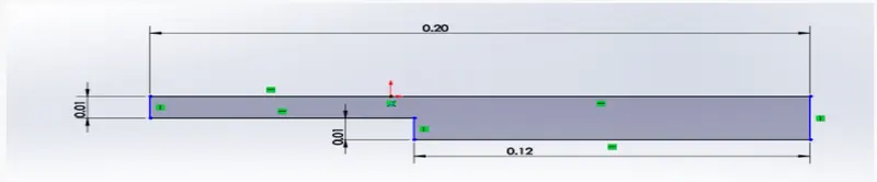
blockMesh description.
1) The flow domain is divided into three blocks.
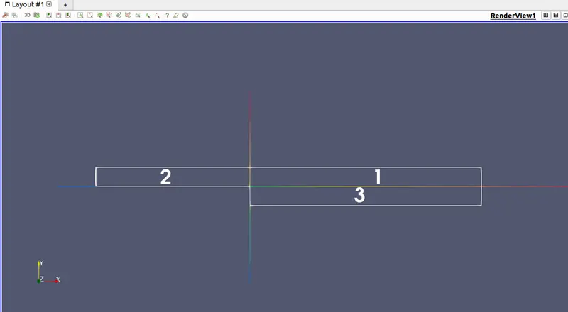
2) The vertices of the blocks are named starting from block 1.
Example:-
convertToMeters 0.001;
vertices
(
(0 0 0) //vertex 0
(120 0 0) //vertex 1
(120 10 0) //vertex 2
(0 10 0) //vertex 3
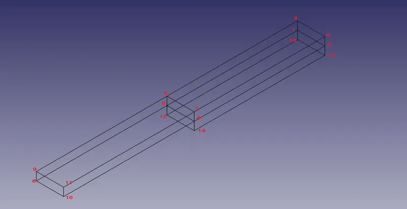
3) Mesh generation
The meshing of the blocks is done as follows
hex(0 1 2 3 4 5 6 7)(80 20 1) simpleGrading (1 1 1)
where
1] First brackets specify the vertices of the blocks for which the mesh is generated.
2]Second brackets specify the number of cells along a direction. Order being (nx ny nz).
3]simpleGrading specifies uniform expansion for the mesh in the local x,y,z directions with three ratios (1 1 1).
4) Boundaries
| type | description | |
| Inlet & Outlet | patch | no geometric info about mesh. |
| Front & back | empty | when a solution is required only in 2 dimensions. |
| noSlipWalls | wall | to specify no-slip condition. |
CASE-1
Grading factor = 1.
1] blockMeshDict file: -
/*--------------------------------*- C++ -*----------------------------------*\
 ========= |
 \\ / F ield | OpenFOAM: The Open Source CFD Toolbox
 \\ / O peration | Website: https://openfoam.org
 \\ / A nd | Version: 8
 \\/ M anipulation |
\*---------------------------------------------------------------------------*/
FoamFile
{
 version 2.0;
 format ascii;
 class dictionary;
 object blockMeshDict;
}
// * * * * * * * * * * * * * * * * * * * * * * * * * * * * * * * * * * * * * //
convertToMeters 0.001;
vertices
(
 (0 0 0) //vertex 0
 (120 0 0) //vertex 1
 (120 10 0) //vertex 2
 (0 10 0) //vertex 3

 (0 0 1) //vertex 4
 (120 0 1) //vertex 5
 (120 10 1) //vertex 6
 (0 10 1) //vertex 7

 (-80 0 0) //vertex 8
 (-80 10 0) //vertex 9
 (-80 0 1) //vertex 10
 (-80 10 1) //vertex 11

 (0 -10 0) //vertex 12
 (120 -10 0) //vertex 13
 (0 -10 1) //vertex 14
 (120 -10 1) //vertex 15
);
blocks
(
 hex (0 1 2 3 4 5 6 7) (80 20 1) simpleGrading (1 1 1)  //block 1
 hex (8 0 3 9 10 4 7 11) (200 20 1) simpleGrading (1 1 1)  //block 2
 hex (12 13 1 0 14 15 5 4) (80 10 1) simpleGrading (1 1 1)  //block 3
);
edges
(
);
boundary
(
 inlet
 {
 type patch;
 faces
 (
 (8 10 11 9)
 );
 }
 outlet
 {
 type patch;
 faces
File: /home/shritej/OpenFOAM/shrite…st/cavity/system/blockMeshDict Page 2 of 2
 (
 (13 1 5 15)
 (1 2 6 5)

 );
 }
 frontandBack
 {
 type empty;
 faces
 (
 (10 4 7 11)
 (4 5 6 7)
 (14 15 5 4)
 (0 3 2 1)
 (8 9 3 0)
 (12 0 1 13)
 );
 }
 noSlipWalls
 {
 type wall;
 faces
 (
 (11 7 3 9)
 (7 6 2 3)
 (14 4 0 12)
 (10 8 0 4)
 (14 12 13 15)

 );
 }
);
mergePatchPairs
(
);
// ************************************************************************* / 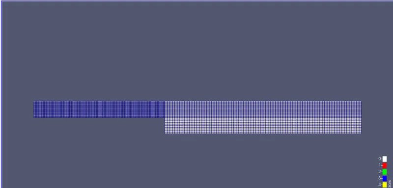
following are the mesh specifications for the blocks
hex (0 1 2 3 4 5 6 7) (80 20 1) simpleGrading (1 1 1) //block 1
hex (8 0 3 9 10 4 7 11) (200 20 1) simpleGrading (1 1 1) //block 2
hex (12 13 1 0 14 15 5 4) (80 10 1) simpleGrading (1 1 1) //block 3
2]The icoFoam solver uses PISO algorithm to solve the governing equations for laminar, incompressible flow of fluids, continuity and momentum equations.
`grad*u = 0`
`del/(delt)(u) + grad*(uoxu) - grad*(nu*gradu) = -gradp`
kinematic viscosity(nu) is choosen 0.01 (m^2/s) to make the flow laminar.
3]The initial pressure and velocity conditions
| inlet | outlet | |
| pressure |
zeroGradient (sets the value to internal field values) |
fixedValue (uniform 0) |
| velocity |
fixedValue uniform(1 0 0) |
zeroGradient |
4]The following is the controlDict file which states the timestep, running time etc for the solver.
/*--------------------------------*- C++ -*----------------------------------*\
 ========= |
 \\ / F ield | OpenFOAM: The Open Source CFD Toolbox
 \\ / O peration | Website: https://openfoam.org
 \\ / A nd | Version: 8
 \\/ M anipulation |
\*---------------------------------------------------------------------------*/
FoamFile
{
 version 2.0;
 format ascii;
 class dictionary;
 location "system";
 object controlDict;
}
// * * * * * * * * * * * * * * * * * * * * * * * * * * * * * * * * * * * * * //
application icoFoam;
startFrom startTime;
startTime 0;
stopAt endTime;
endTime 3;
deltaT 1e-4;
writeControl timeStep;
writeInterval 200;
purgeWrite 0;
writeFormat ascii;
writePrecision 6;
writeCompression off;
timeFormat general;
timePrecision 6;
runTimeModifiable true;
// ************************************************************************* /
Timestep(deltaT) is fixed at 1e-4 to adjust the Courant number to make the solution stable according to the CFL condition.
Velocity profile after reaching steady state.
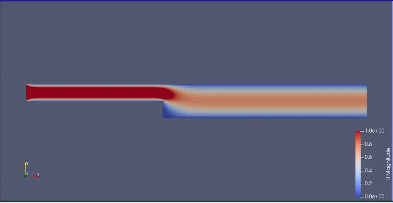
The velocity profile displays a steady laminar flow, flow separation at the step with no vortices.
The velocity profile is uniform over the entire cross-section.
No-slip boundary condition (u = 0) observed in blue along the walls in the figure.
The plot for U(magnitude) vs x(along the flow) is
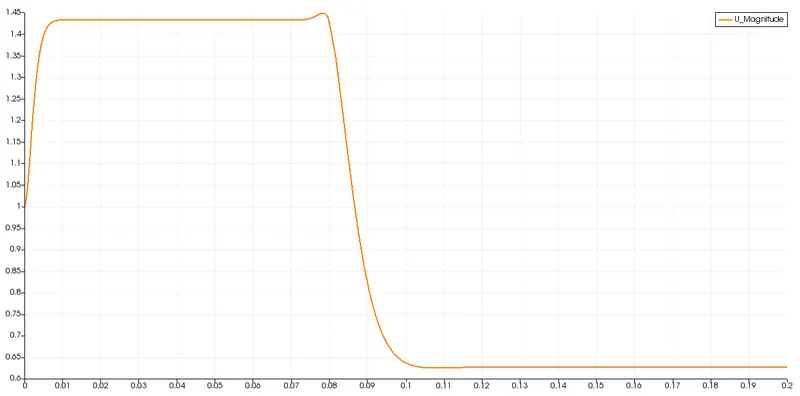
The velocity at the inlet is 1m/s. Along the centerline of the duct, the velocity increases due to entrance effects and reaches a constant value after the flow is developed. At the step, the flow experiences a sudden expansion and separates from the bottom wall. The velocity thereafter decreases to maintain continuity and attains a steady state as well.
The value of the velocity at 0.085 m from the entrance is U = 1.1032 m/s.
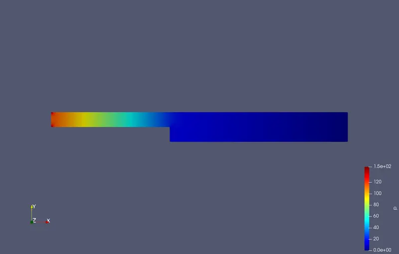
The pressure distribution inside the domain: -
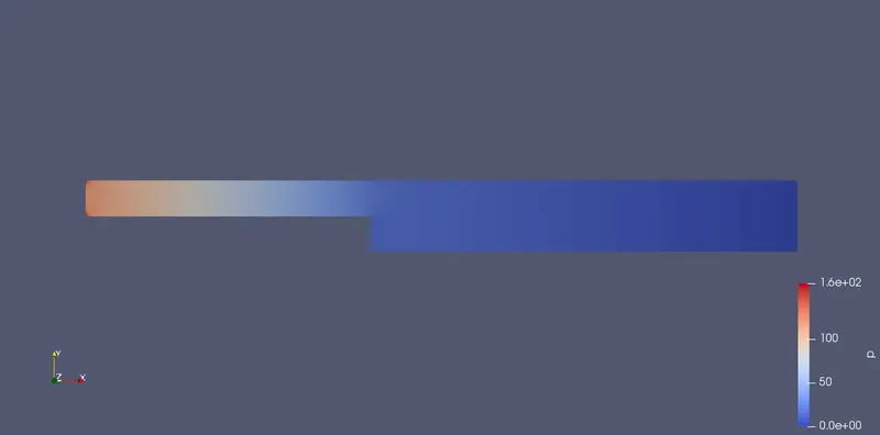
At the inlet, pressure develops according to the inlet conditions and hence is specified as zeroGradient. The pressure value reaches atmospheric at the outlet, as specified in the initial conditions.
CASE-2
Grading factor = 0.2
The grading for the blocks is as
hex (0 1 2 3 4 5 6 7) (80 20 1) simpleGrading (5 1 1) //block 1
hex (8 0 3 9 10 4 7 11) (200 20 1) simpleGrading (0.2 1 1) //block 2
hex (12 13 1 0 14 15 5 4) (80 10 1) simpleGrading (5 0.2 1) //block 3
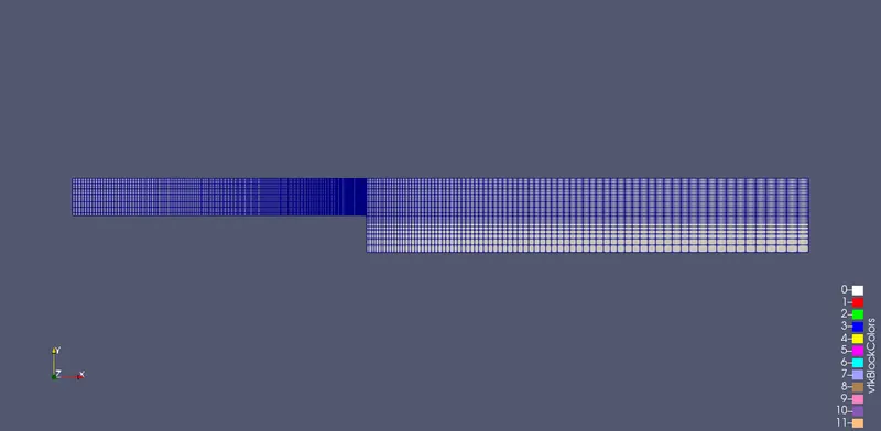
The mesh is finer near the walls and at the section where the flow experiences sudden expansion.
The velocity distribution
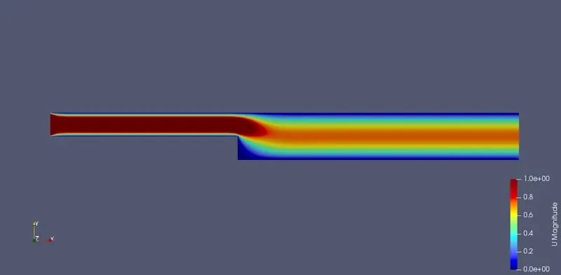
Velocity plot
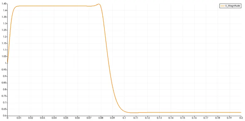
The velocity at 0.085 m from inlet is 1.109 m/s.
Pressure distribution
Mesh grading factor
for grading factor =1 velocity at 0.085m from inlet = 1.1032 m/s.
for grading factor = 0.2 velocity at 0.085m from inlet = 1.1093 m/s.
1. There is not much difference between the values for this case.
2. Grading factor is used to change the mesh to fine or coarse according to the requirement. Here, the mesh is made fine at the step wall. A fine mesh usually results into more accurate calculations of flow variables, a coarse mesh is less accurate.
3. A fine mesh requires more iterations and computing time. Some changes in the timestep or number of cells have to be made to keep the Courant number in limits for stability.