Week 9 - Parametric study on Gate valve.
Aim :
To perform a parametric study on the gate valve simulation by setting the opening from 10 % to 80%.
Objective :
- To perform a simulation for the different gate valve opening which is 10% to 80%.
- To obtain the mass flow rates at the outlet for each design point.
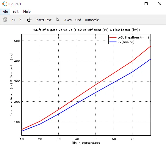
- To calculate the flow coefficient and flow factor for each opening and plot the graph.
- To discuss the results of the mass flow rate and flow coefficient.
Introduction :
A gate valve can be defined as a type of valve that uses a gate or wedge type disk and the disk moves perpendicular to the flow direction of fluid to start or stop the fluid flow. A gate valve is the most common type of valve that is used in any process plant. In service, these valves are either in fully open or fully closed position. When the gate valve is fully open, the disk of a gate valve is completely removed from the flow. Due to this, there is a very little pressure drop when fluid passes through a gate valve. Shown here are Gate Valves upon whom Stem Cap and T-Key are being installed for easy access while opening and closing the valve from a distance.
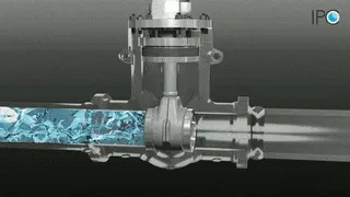
Working of gate valve
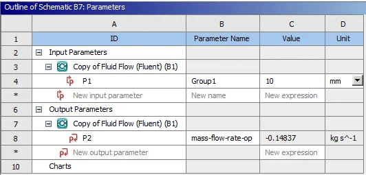
In this project the intend is to perform the simulation for different openings of gate valve can be done separately, however it would consume extensive analysis time. To set-up same simulation repetatively for a single different input condition is not the ideal way. In order to avoid this, parametric analysis is used in ANSYS Fluent which can be used to simulate all the cases with little work. The varying parameter in this case is the lift of the gate valve which can be set as "input parameter" and mass flow rate at the outlet can be set as "output parameter". This reduces monotonous work and calculates desired output for different cases. Moreover, the flow coeffcient and flow factor can be calculated using output parameters (mass flow rate and pressure drop) assigned for each case.
Theory :
Flow coefficient (Cv) :
Valve Flow Coefficient (Cv) is a valve's capacity for a liquid or gas to flow through it. It is technically defined as “the volume of water at 60°F (in US gallons) that will flow through a valve per minute with a pressure drop of 1 psi across the valve.
Mathematically flow coefficient can be given as,
Cv = `Qsqrt((S.G)/(nablap))`
where, Cv = Flow coefficient (US gallons/min)
Q = Flow rate (US gallons/min)
SG = Specific gravity of the fluid.
`nabla`p = Pressure drop (Psi)
The use of flow coeffcient offers a standard method of comparing valve capacities and sizing valves for specific applications that is widely accepted by industry.
Flow Factor (Kv) :
Kv is defined as the flow of water through the valve or orifice that has that rating, in cubic meters per hour (m³/hr), that creates a pressure drop of one bar with temperature ranging from 5 to 30 degree C. So a valve with a Kv rating of 1 at 25% open will cause a pressure drop of 1 bar when 1 m³/hr of 30 degree C water flows through it. It is the metric equivalent of the flow factor Cv, dimensioned in English units.
Flow factor can be given as,
Kv = `Qsqrt((S.G)/(nablap))`
where, Kv = Flow factor (`m^3`/hr)
Q = Flow rate (`m^3`/hr)
SG = Specific gravity of the fluid.
`nabla`p = Pressure drop (bar)
Flow factor (Kv) can be calculated from flow coefficient (Cv) using the equation,
Kv = 0.865Cv
Project Methodology :
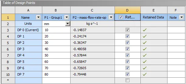
Initially the gate valve geometry was imported in SpaceClaim and cad clean-up (removal of extra edges) was performed. Subsequently lift of the gate valve was set to be as parameter and volume was extracted. Then the geometry was updated in meshing module and the mesh was generated. The meshed geometry was imported into the Fluent set-up by defining initial conditions, boundary conditions, materials, selecting turbulence model, and activating gravity in the negative z-direction. The report definition of mass flow rate at the outlet was created and set as an output parameter for the simulation. After resulting converged solution, the design points were created in the "Parameters" tab for the varying lift of the gate valve from 20 % to 80 %. Subsequently after running each case the results were extracted (Mass flow rate at the outlet and Pressure drop) and were plotted against opening percentage of lifting of the gate valve.
Pre-processing :
Geometry :
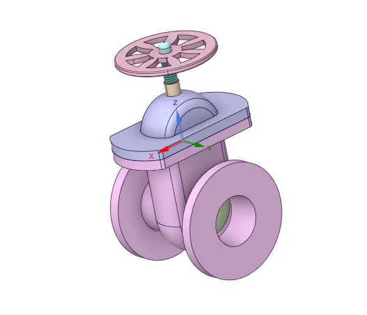
Import the geometry in spaceclaim and CAD cleanup is done here.
Nomenclature :
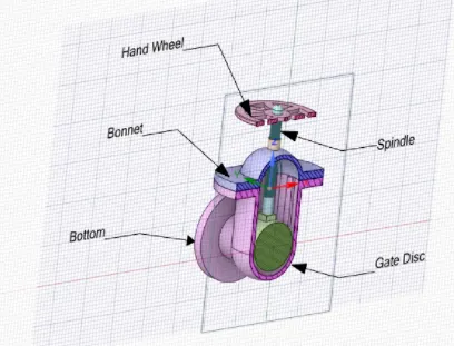
Bottom Elongation :
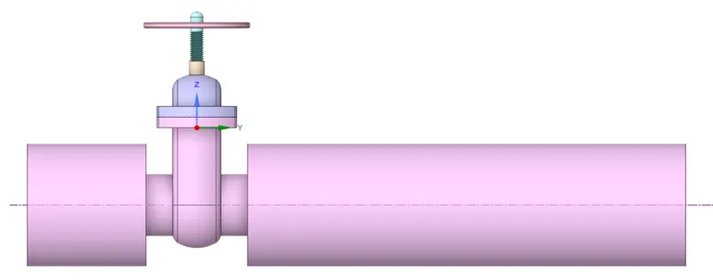
The bottom inlet and outlet pipes were elongated using "Pull" tool to have sufficient length for the fluid flow. Outlet section was intently kept long to have a fully developed region which will be free from flow characteristics fluctuations.
Lifting the Gate Disc :
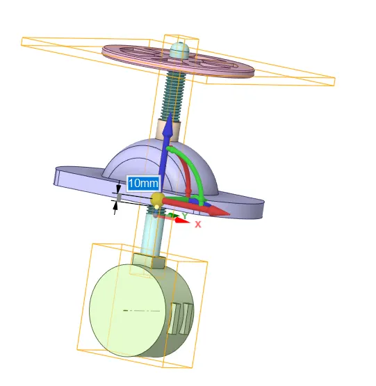
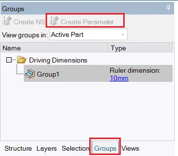
In order to lift the gate disc all the components except spindle and gate disc were selected to hide for convenience. Using "Move" tool the gate disc component was selected by choosing upward direction and was lifted by 10 mm. In groups "Create Parameter" tab was selected and parameter group got created with ruler dimension of 10 mm. So this lifting movement of the gate disc is parameterized and can be varied for all the cases in the "Parameters" tab in the Workbench window.
Mesh :
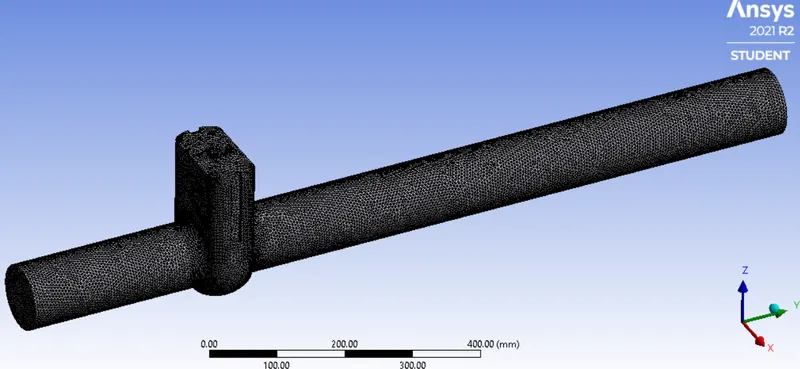
| Mesh Type | Unstructured mesh (Tetrahedrons) |
| Element Size | 5 mm |
| Maximum Element Size | 10 mm |
| Nodes | 83,698 |
| Elements | 4,14,269 |
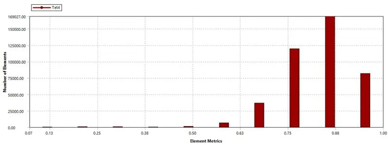
Element Quality :
Setup :
|
Gravity |
-9.81 in the Z direction | |
|
Solver Type |
Pressure-Based |
|
|
Velocity Formulation |
Absolute |
|
|
Time |
|
|
|
Models |
Viscous model : K-epsilon, Realize, Scaled wall functions. Energy model : OFF |
|
|
Material |
Fluid type : Water Solid-type : Aluminium |
|
|
Cell zones |
Fluid type : water Solid : Al |
|
|
Boundaries |
Pressure Inlet : 10pa(gauge pressure) Wall : wall Outlet : 0pa(gauge pressure) Volume : interior |
|
|
Reference values |
Standard |
|
|
Definitions |
Mass flow rate | |
|
Initialization |
Standard |
Post-processing :
A) 10% Opening :
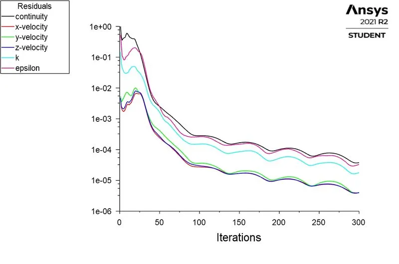
1. Residuals :
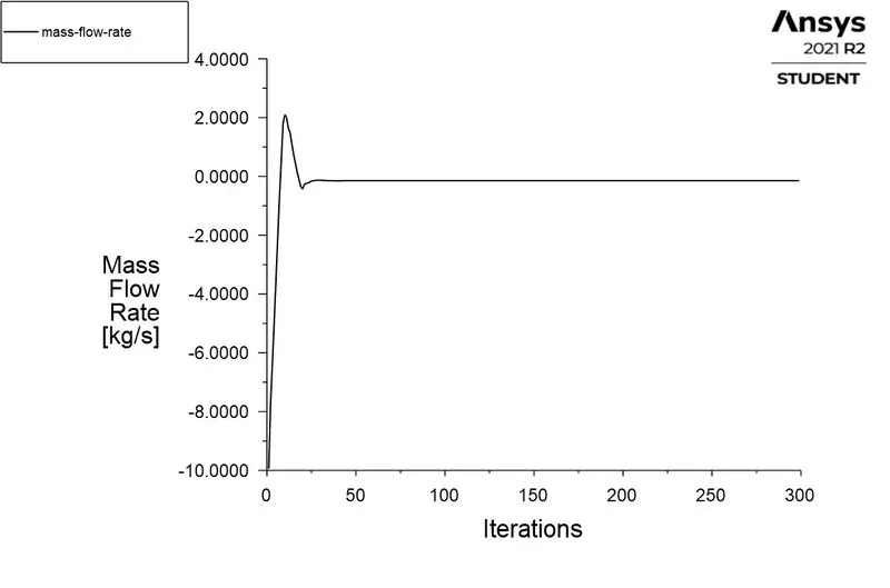
2. Mass Flow Rate :

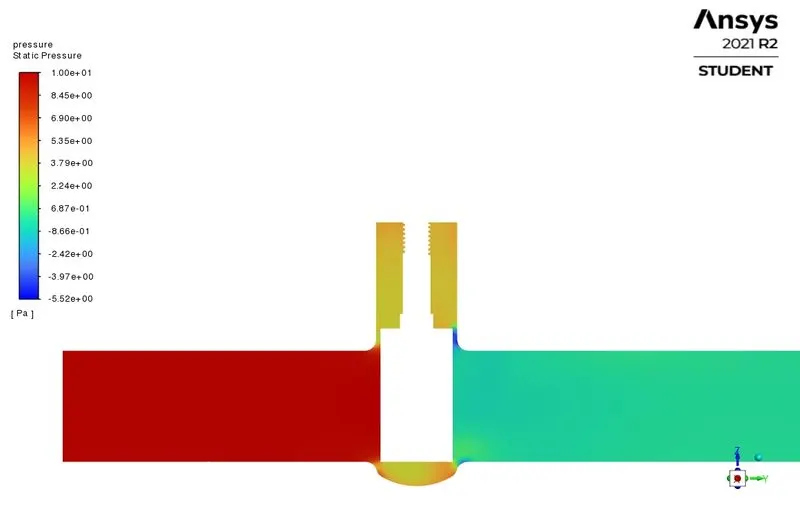
3. Pressure Contour :
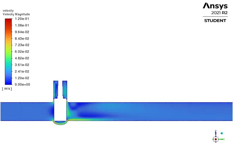
4. Velocity Contour :
Parameters tab :
B) 20% Opening :
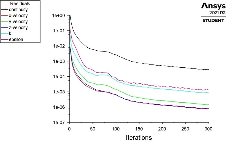
1. Residuals :
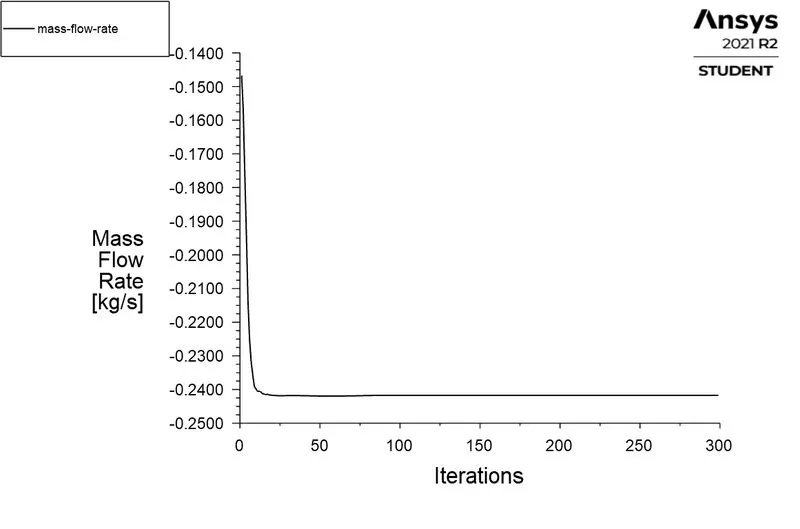
2. Mass Flow Rate :

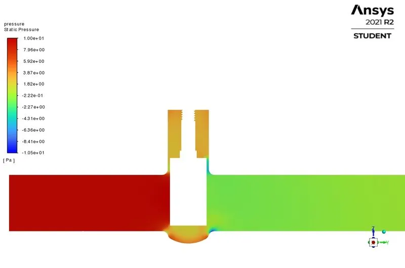
3. Pressure Contour :
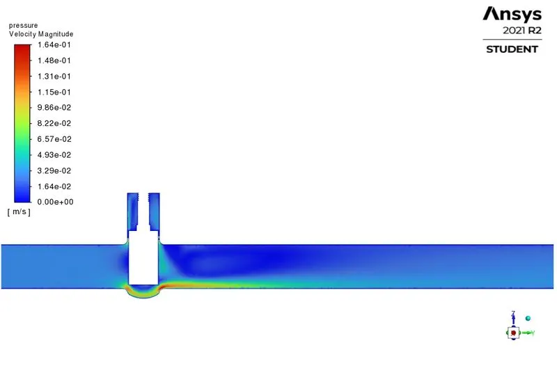
4. Velocity Contour :
c) 30% Opening :
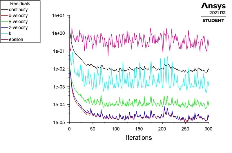
1. Residuals :
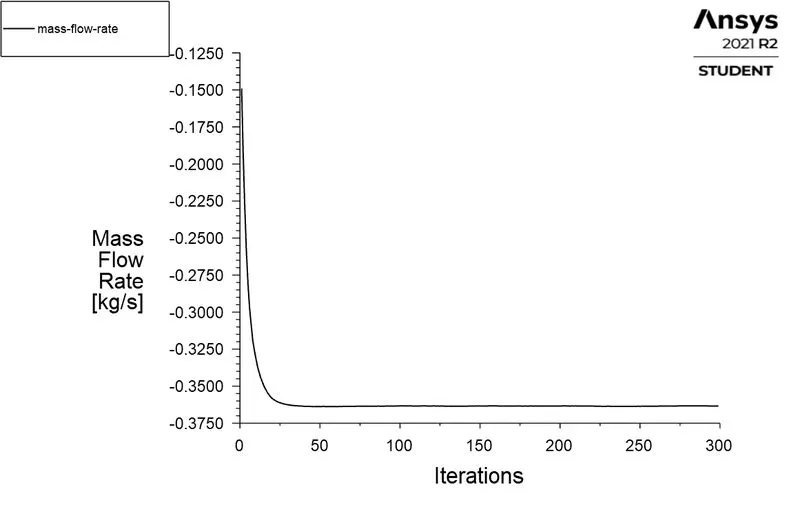
2. Mass Flow Rate :

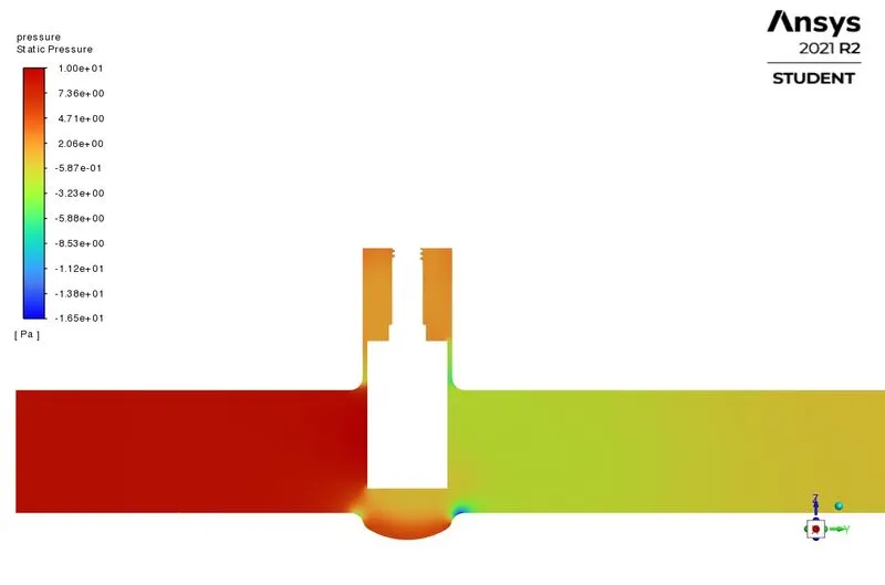
3. Pressure Contour :
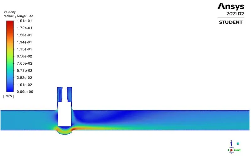
4. Velocity Contour :
d) 40% Opening :
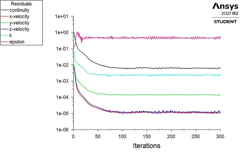
1. Residuals :
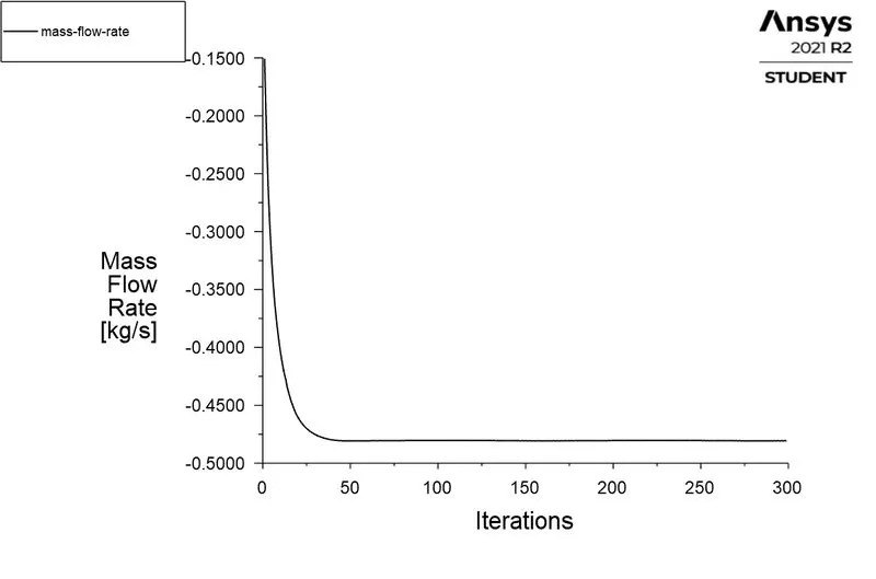
2. Mass Flow Rate :

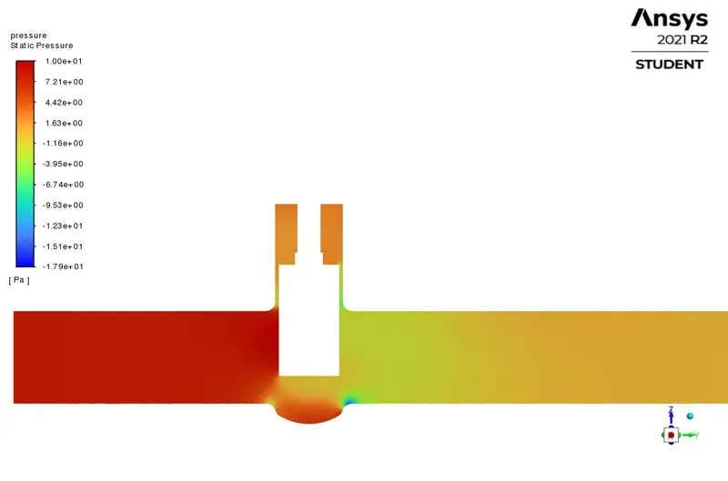
3. Pressure Contour :
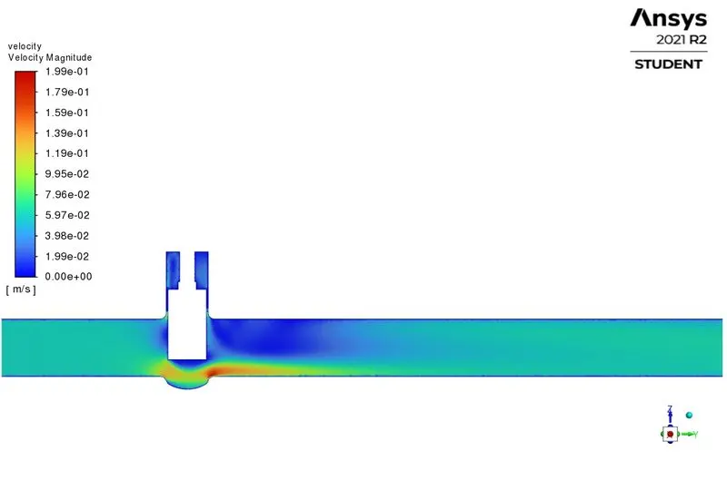
4. Velocity Contour :
e) 50% Opening :
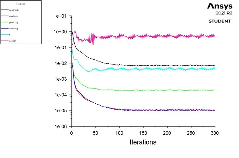
1. Residuals :
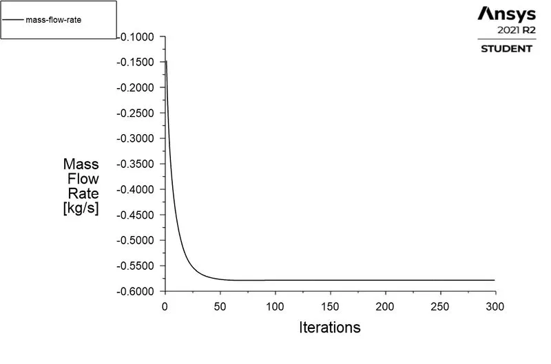
2. Mass Flow Rate :

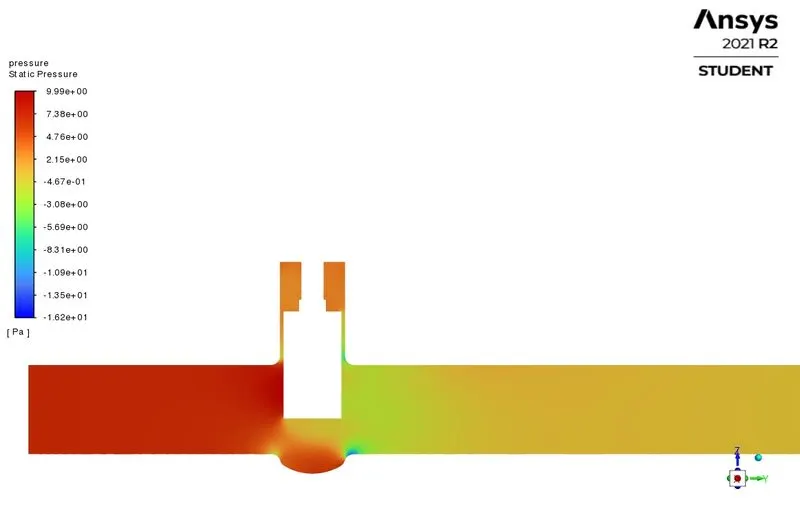
3. Pressure Contour :
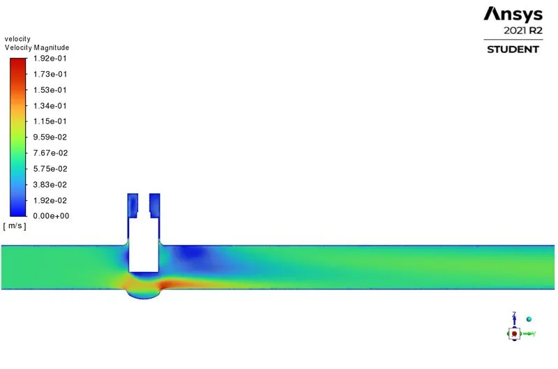
4. Velocity Contour :
f) 60% Opening :
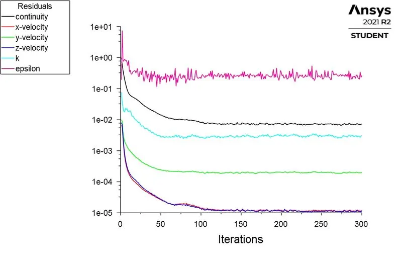
1. Residuals :
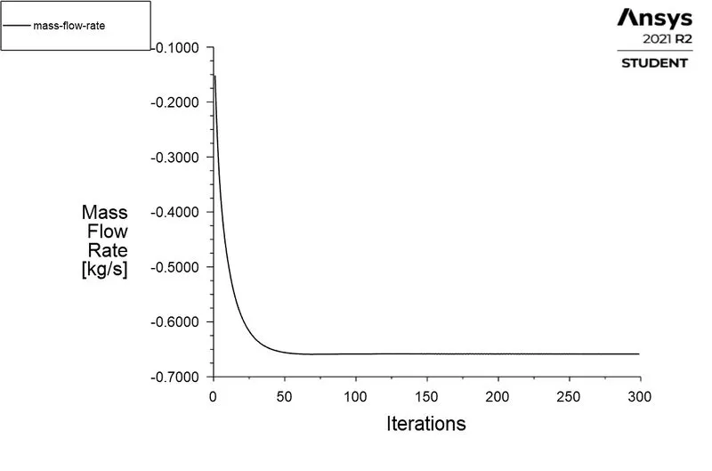
2. Mass Flow Rate :

3. Pressure Contour :
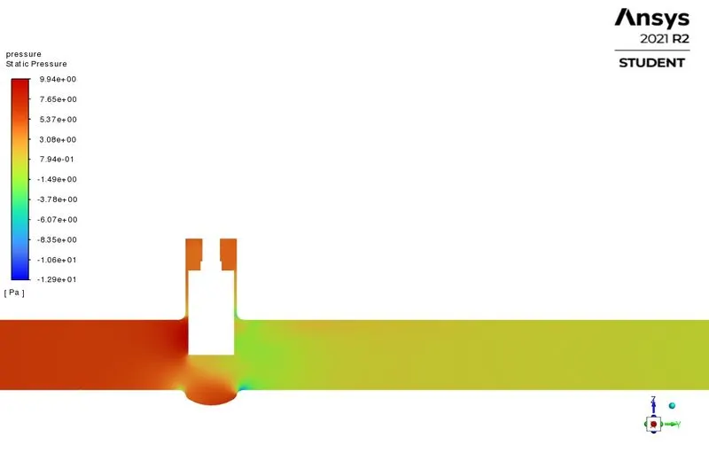
4. Velocity Contour :
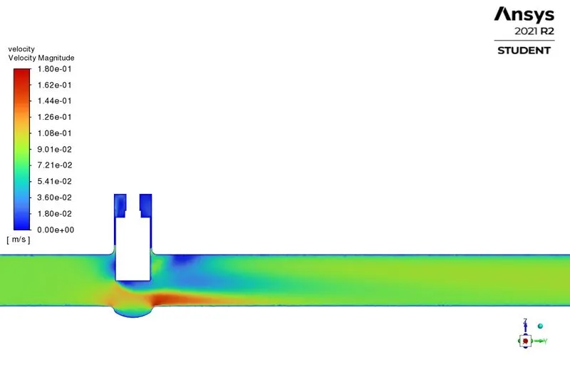
g) 70% Opening :
1. Residuals :
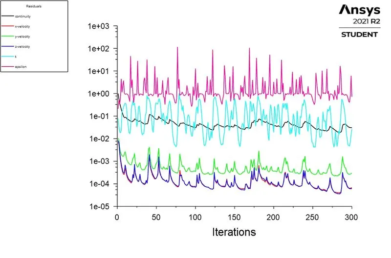
2. Mass Flow Rate :
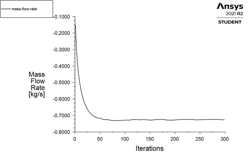

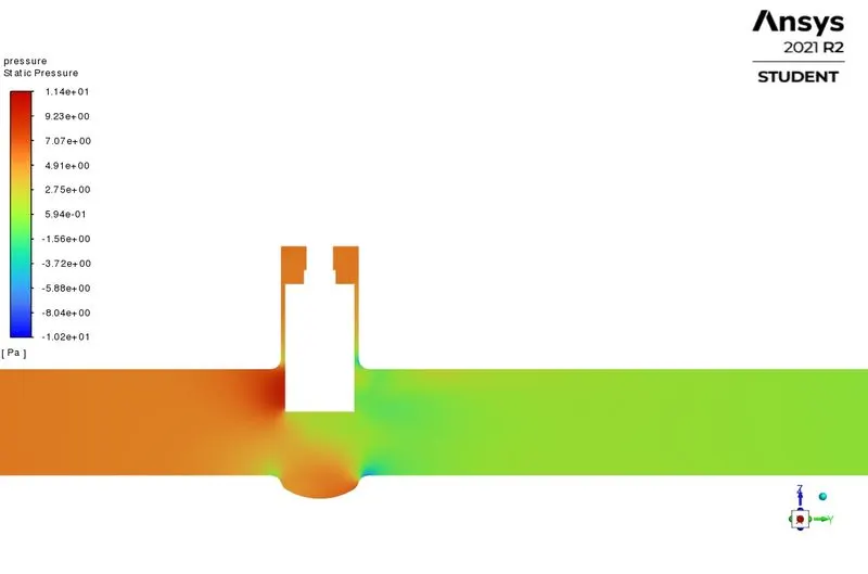
3. Pressure Contour :
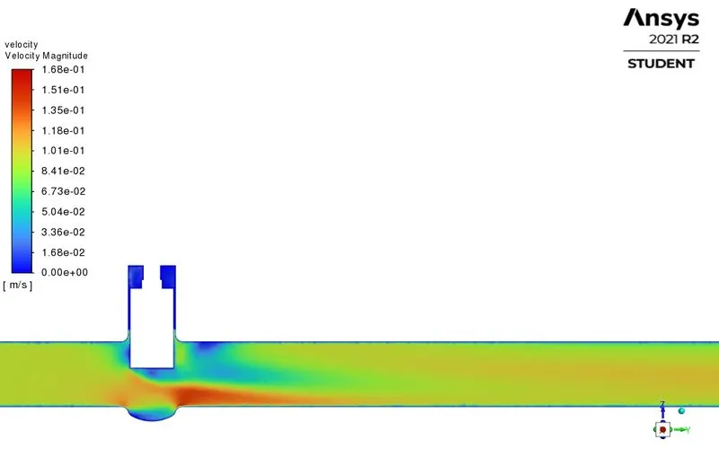
4. Velocity Contour :
h) 80% Opening :
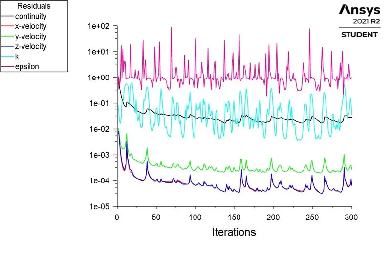
1. Residuals :
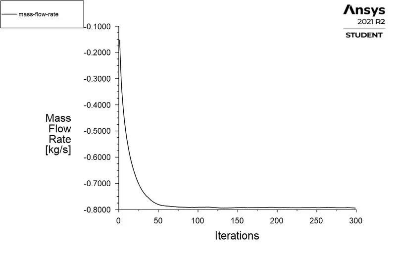
2. Mass Flow Rate :

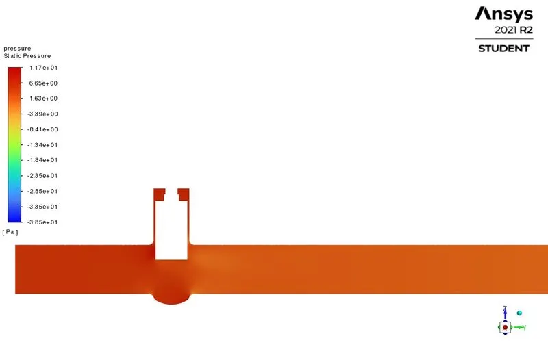
3. Pressure Contour :
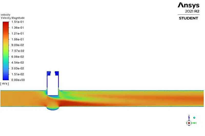
4. Velocity Contour :
Observation Table :
|
Lift of the Gate Valve(mm) |
Mass Flow Rate (Kg/s) |
Mass Flow Rate (US gallons/min) |
Pressure Drop (Pa) |
Pressure Drop (Psi) |
Flow coefficient(Cv) |
Flow Factor(Kv) |
| 10 | 0.14837 | 2.3517 | 9.8208 | 1.4244e-003 | 62.311 | 53.899 |
| 20 | 0.24174 | 3.8316 | 9.5243 | 1.3814e-003 | 103.092 | 89.174 |
| 30 | 0.36347 | 5.7610 | 8.9247 | 1.2944e-003 | 160.126 | 138.509 |
| 40 | 0.48057 | 7.6170 | 8.1195 | 1.1776e-003 | 221.961 | 191.997 |
| 50 | 0.57844 | 9.1683 | 7.2761 | 1.0553e-003 | 282.228 | 244.127 |
| 60 | 0.65847 | 10.437 | 6.4698 | 9.3837e-004 | 340.713 | 294.716 |
| 70 | 0.72605 | 11.508 | 5.7140 | 8.2874e-004 | 399.752 | 345.785 |
| 80 | 0.79448 | 12.593 | 4.8707 | 7.0644e-004 | 473.795 | 409.833 |
Conclusion :
- The parametric study on a gate valve with different valve lift was successfully studied.
- The mass flow rate gradually increases as the lift of gate disc is increased.
- Flow coefficient / flow factor increases with the lift of the gate valve.
- However, there is inverse relationship between the pressure drop and gate valve lift.
- The flow coefficient / flow factor changes according to the gate valve dimensions and it is important to account for these quantities to select gate valve for an appropriate application.
- Parametric study is time reducing option when studying the effects of changes of certain parameters on a system.
References :