AIR STANDARD CYCLE
AIM :
To write a MATLAB code for a study of an otto cycle and to find an thermal efficiency of an engine.
GOVERNING EQUATIONS :
`V_s =(pid^2l)/4`
`V_c=(V_s)/(cr-1)`
`PV^gamma` = Constant
`gamma = (C_p)/(C_v)`
`(PV)/(T)` = Constant
R = `(cl)/(a)`
`a = (Stroke)/(2)`
`V/V_c` = `1+(1)/(2)(cr-1)[R+1-costheta+sqrt(R^2-sin^2theta)]`
`eta = 1-(1)/(cr^(gamma-1))`
NOTATIONS:
P - pressure of an ideal gas.
V - volume of an ideal gas.
T - Temperature of an ideal gas.
`V_s` - Clearance volume.
`V_c` - Swept volume.
d - Bore of a cylinder.
l - Stroke of a cylinder.
`C_p` - Specific heat capacity at constant pressure.
`C_v` - Specific heat capacity at constant volume.
cr - Compression ratio.
cl - Connecting rod length.
a - Crank radius.
R - Ratio between connecting rod length and crank radius.
`eta` - Thermal efficiency of an otto cycle.
`gamma` - specific heat ratio.
OBJECTIVE :
To study about the codes which is used to create a graph which represents the otto cycle and to find the thermal efficiency of an engine.
THEORY :
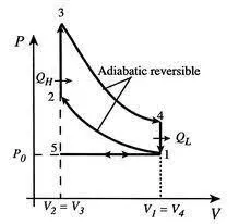
OTTO CYCLE :
An Otto cycle is an idealized thermodynamic cycle that describes the functioning of a typical spark ignition piston engine. It is the thermodynamic cycle most commonly found in automobile engines(petrol engine).
Process (5-1) : Suction stroke
In this process the working fluid is sucked from the atmosphere inside the cylinder.
Process (1-2) : Isentropic compression
The working fluid compresses isentropically as the piston moves from bottom dead center (BDC) to top dead center (TDC).
Process (2-3) : Constant volume heat addition
In this process, a spark is ignitated rapid burning occurs inside the piston; therefore, the heat addition takes place at the constant volume.
Process (3-4) : Isentropic expansion
In this process, the working fluid expands isentropically and produces the useful work for the cycle as the piston moves from top dead center (TDC) to bottom dead center (BDC).
Process (4-1) : Constant volume heat rejection
The heat is removed by expelling the exhaust gas to the atmosphere at constant volume as the piston moves from bottom dead center (BDC) to top dead center (TDC).
MAIN PROGRAM :
clear all
close all
clc

% Inputs
P1=101325;
T1=500;
T3=5000;
gamma1=1.4;
gamma2=1.3;
Bore = 0.1;
Stroke = 0.1;
% connecting_rod_length = cl
cl = 0.15;
% compression ratio
cr = 7;

% calculation of clearance volume and swept volume
V_s = (pi/4)*(Bore)^2*Stroke;
V_c = V_s/(cr-1);

% variable at stage1
V1 = V_s+V_c;

% variable at stage2
V2 = V_c;

% P2V2^gamma = P1V1^gamma
P2 = P1*(V1/V2)^gamma1;

% P2V2/T2 = P1V1/T1

T2 = P2*V2*T1/(P1*V1);

constant = P1*V1^gamma1;

V_compression = engine_kinematics(Bore,Stroke,cl,cr,180,0);

P_compression = constant./(V_compression).^gamma1;

% variable at stage3

V3 = V2;

P3 = T3*P2*V2/(V3*T2);

constant_c = P3*V3^gamma2;

V_expansion = engine_kinematics(Bore,Stroke,cl,cr,0,180);

P_expansion = constant_c./(V_expansion).^gamma2;

% variable at stage4

V4 = V1;

P4 = P3*(V3/V4)^gamma2;

% Thermal efficiency
thermal_efficiency = 1 -1/cr^(gamma1-1)
figure(1)
hold on

plot(V1,P1,'*','color','r')
plot(V_compression,P_compression)
plot(V2,P2,'*','color','b')
plot([V2 V3],[P2 P3])
plot(V3,P3,'*','color','g')
plot(V_expansion,P_expansion)
plot(V4,P4,'*','color','g')
plot([V4 V1],[P4 P1])
xlabel('volume')
ylabel('pressure')
grid on
legend('state 1','Isentropic compression','state 2','Constant volume heat addition','state 3','Isentropic expansion','state 4','Constant volume heat rejection')
title('otto cycle')
SUB PROGRAM :
function [V] = engine_kinematics(Bore,Stroke,cl,cr,start_cranck,end_crank)

V_s = (pi/4)*(Bore)^2*Stroke;
V_c = V_s/(cr-1);

% calculation of crank pin radius
a = Stroke/2;

R = cl/a;

% V/V_c = 1+0.5(cr-1)[(R+1-cos(theta))-(R^2-sin^2(theta))^0.5]
theta = linspace(start_cranck,end_crank,180);
term1 = 0.5*(cr-1);
term2 = R+1-cosd(theta);
term3 = (R^2-(sind(theta)).^2).^0.5;

V = (1+term1.*(term2-term3)).*V_c;
end
PROGRAM EXPLANATION :
- Assign all the inputs such as bore of cylinder, stroke of a cylinder, connecting rod length, compression ratio, specifc heat ratio, initial state pressure, temperature and the temperature after heat addition.
- Then find the value of pressure, volume and the temperature at each stage using governing equations.
- After all the state parameters are found then using that state parameters thermal efficiency is calculated.
- Then plot the pressure and volume points of an each stage using plot command.
- In order to draw a curve for constant volume heat addition and constant volume heat rejection there is no problem because it is an straight line.
- In the case of isentropic expansion and compression it is not a straight line so there is a relationship between volume of a cylinder and a crank angle.
- From that relation we can identiy how volume changes with respect to the crank angle at isentropic compression amd expansion stage is calculated .
- In order make the program clear and understandable and to reduce the size of a program calculation of isentropic compression amd expansion stage is done inside the function(engine_kinematics) called as sub program.
- This sub program is called inside a main program to get a output of that function.
- Then using the thermodynamic relation how pressure changes with respect to volume compression and volume expansion at isentropic stage is calculated.
- Then plot all the results using plot command.
- The legend command is used for displaying details about the plots and curve in the graph.
OUTPUT :
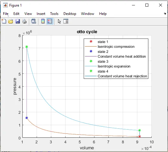
CONCLUSION :
- The code which is used to plot otto cycle is generated.
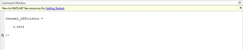
- The thermal efficiency of an otto cycle is calculated .
- The thermal efficiency of an otto cycle is 54.08%.
- The thermal efficiency of an otto cycle depends on the compression ratio and the specific heat ratio if we increase the compression ratio the thermal efficiency will get increased.
- But we can increase a compression ratio to a certain limit. Because high value of compression ratio leads to knocking so compression ratio should be kept optimum.
- If we increase the specific heat ratio thermal efficiency will also get increased, For example assume gamma = 1.5. This value is applicable only to monoatomic gases(i.e., inert gas) which is practically impossible.
- No IC engine can work with an inert gas. In practice, the nitrogen in the air used in the engine limits specific heat ratio to less than 1.4, and the fuels used in IC engines react to form carbon dioxide, water, and other, heavier hydrocarbon molecules, which further reduces specific heat ratio. A commonly selected value of specific heat ratio is 1.4 for the compression stroke and 1.3 for the expansion stroke.