Week 9 - Parametric study on Gate valve.
AIM:
- To perform Parametric study on a Gate Valve by setting the opening from 10% to 80%.
OBJECTIVE:
- To perform the simulation of a Gate Valve and perform the Parametric Study by setting the gate opening from 10% to 80%.
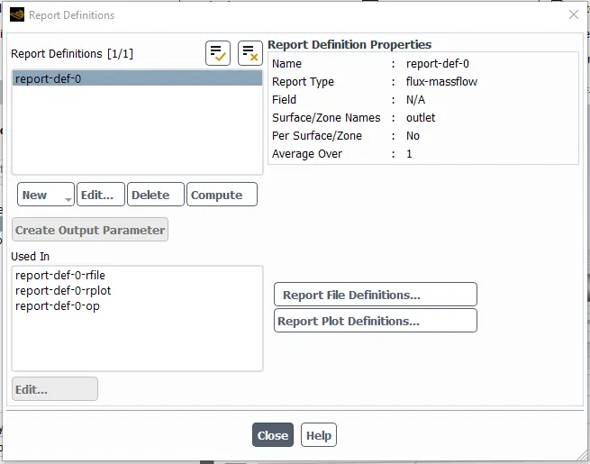
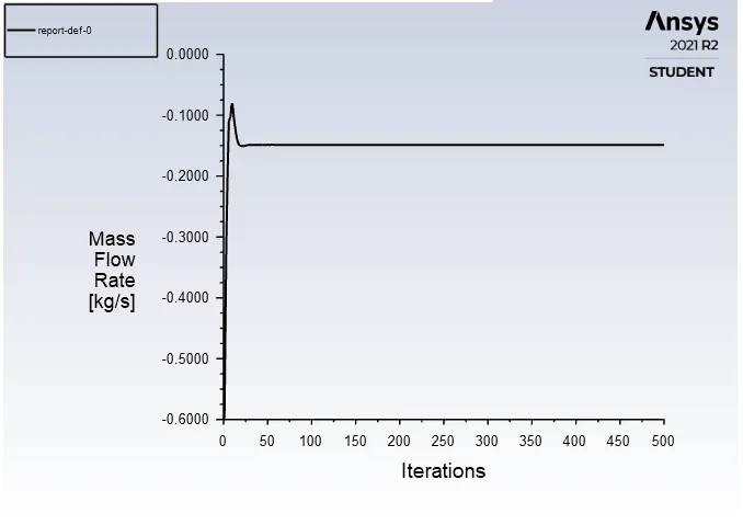
- To obtain the mass flow rates at the outlet for every design point.
- To calculate the Flow coefficient and the Flow factor for every opening and plotting the graph between them.
- To plot various plots and contours as per required.
INTRODUCTION:
GATE VALVE:
- A gate valve, also known as a sluice valve, is a valve that opens by lifting a barrier (gate) out of the path of the fluid. Gate valves require very little space along the pipe axis and hardly restrict the flow of fluid when the gate is fully opened. The gate faces can be parallel but are most commonly wedge-shaped (in order to be able to apply pressure on the sealing surface).
- Gate valves are used to shut off the flow of liquids rather than for flow regulation. When fully open, the typical gate valve has no obstruction in the flow path, resulting in very low flow resistance. The size of the open flow path generally varies in a nonlinear manner as the gate is moved. This means that the flow rate does not change evenly with stem travel. Depending on the construction, a partially open gate can vibrate from the fluid flow.
- Gate valves are mostly used with larger pipe diameters (from 2" to the largest pipelines) since they are less complex to construct than other types of valves in large sizes.
- At high pressures, friction can become a problem. As the gate is pushed against its guiding rail by the pressure of the medium, it becomes harder to operate the valve. Large gate valves are sometimes fitted with a bypass controlled by a smaller valve to be able to reduce the pressure before operating the gate valve itself.
- Gate valves without an extra sealing ring on the gate or the seat are used in applications where minor leaking of the valve is not an issue, such as heating circuits or sewer pipes.
- A gate valve controls the medias flow by lifting the gate (open) and lowering the gate (closed). A gate valves distinct feature is the straight-through unobstructed passageway, which induces minimal pressure loss over the valve. The unobstructed bore of a gate valve also allows for a pig's passage in cleaning pipe procedures, unlike butterfly valves. Gate valves are available in many options, including various sizes, materials, temperature and pressure ratings, and gate and bonnet designs.
- Gate valves tend to be slightly cheaper than ball valve of the same size and quality. They are slower in actuation than quarter-turn valves and are for applications where valve operation is infrequent, such as isolating valves. Gate valves should be used either fully open or fully closed, not to regulate flow. Automated gate valves exist with either an electric or pneumatic actuator, but a manual gate valve is cost-effective since they have infrequent usage.
FLOW COEFFICIENT:
- The flow coefficient of a device is a relative measure of its efficiency at allowing fluid flow. It describes the relationship between the pressure drop across an orifice valve or other assembly and the corresponding flow rate.
- Mathematically the flow coefficient Cv (or flow-capacity rating of valve) can be expressed as:
- `C_v = Qsqrt((SG)/(triangleP))`
- Where,
- Q = Mass Flow Rate (Gallons/minute)
- SG = Specific Gravity = Density of the material / Density of the reference material = 1
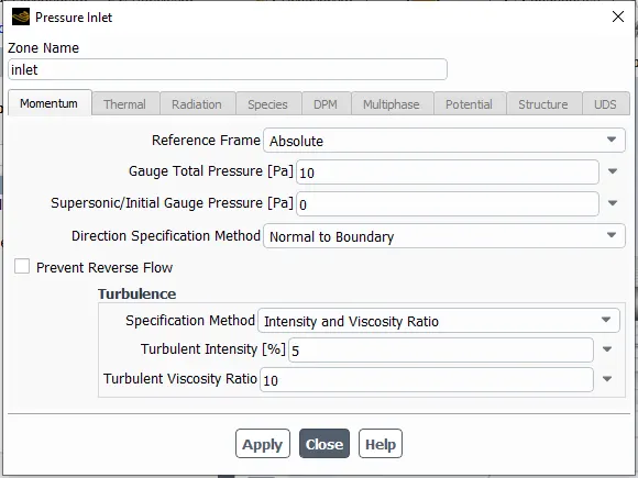
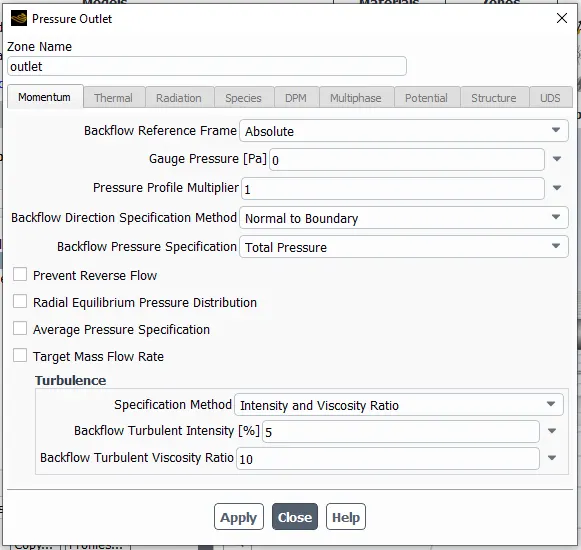
- `triangle P` = Pressure Difference = Pressure at Outlet - Pressure at Inlet = 0 - 10 = -10 Pa= 0.00145038 Psi
FLOW FACTOR:
- The Flow Factor can be calculated from the Flow Coefficient and can be expressed as:
- `K_v = 0.865*C_v`
PROBLEM METHODOLOGY:
CASE - 1:
- Gate Opening = 10mm
GEOMETRY:
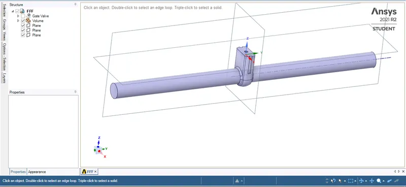
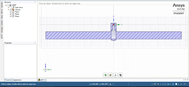
MESHING:
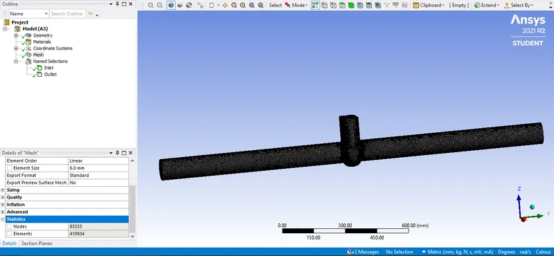
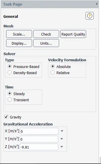
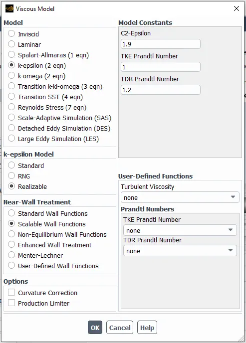
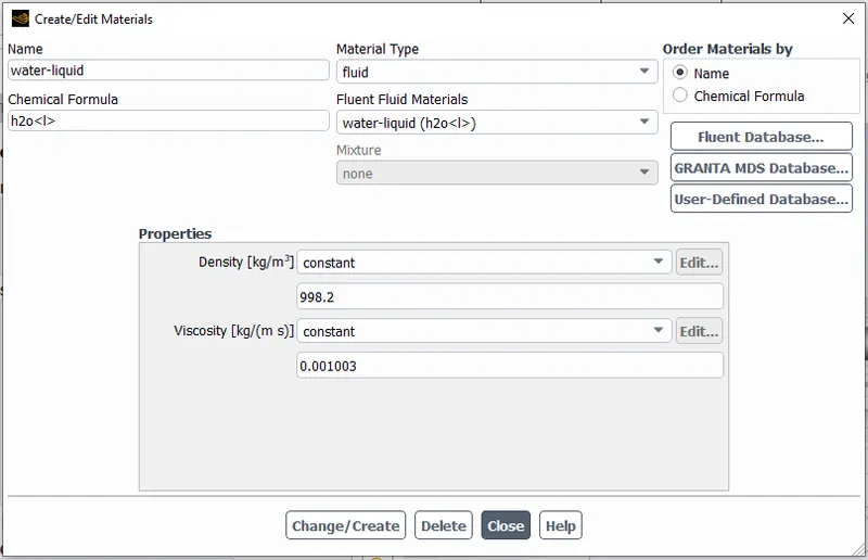
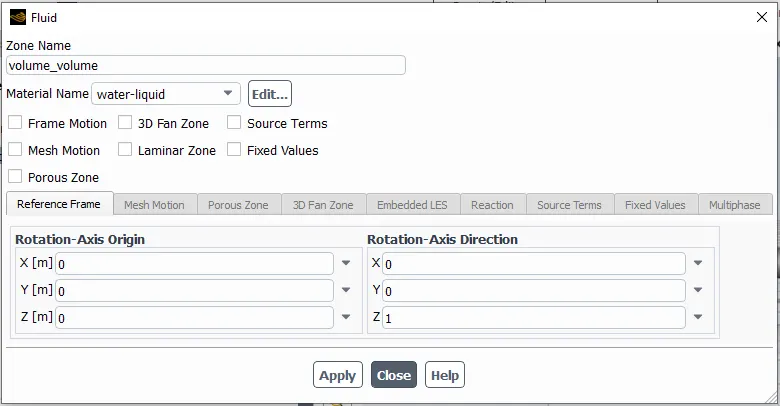
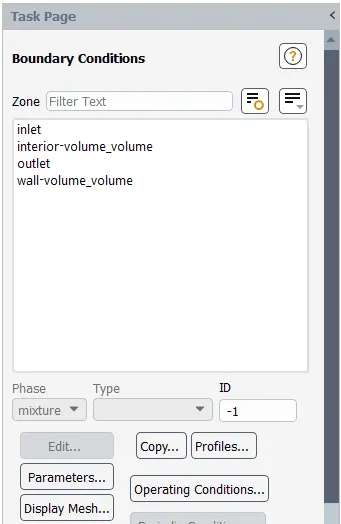
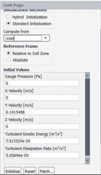
SETUP:
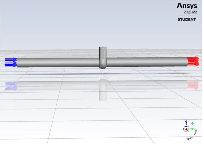
RESULTS:
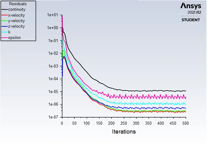
RESIDUALS:
MASS FLOW RATE PLOT:

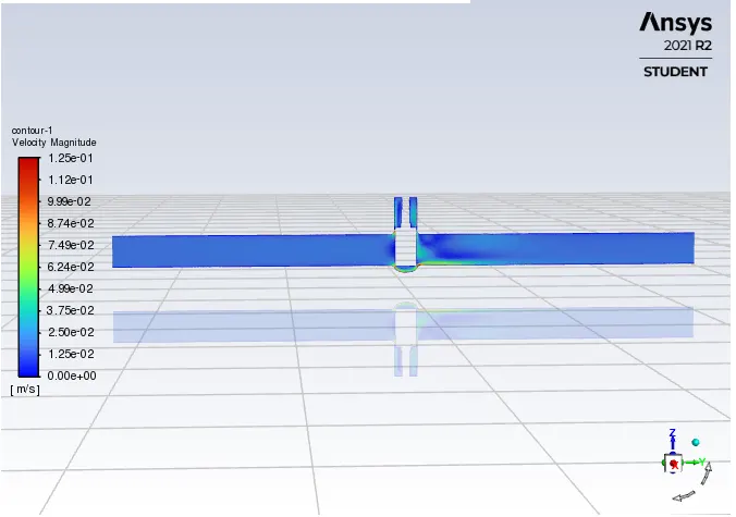
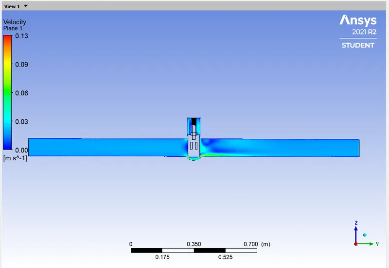
VELOCITY CONTOUR:
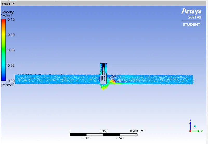
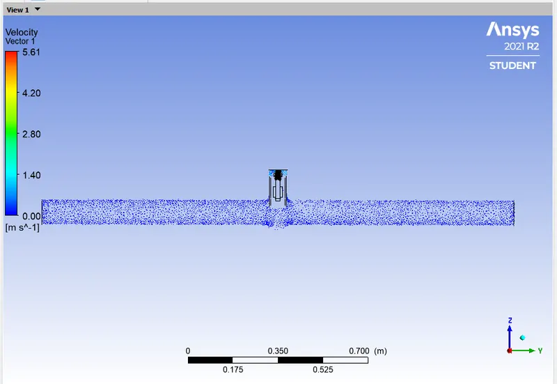
VELOCITY VECTOR:
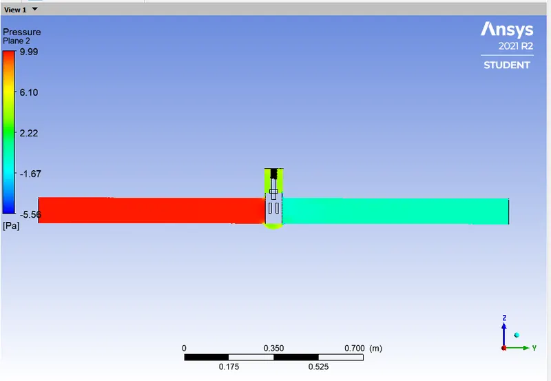
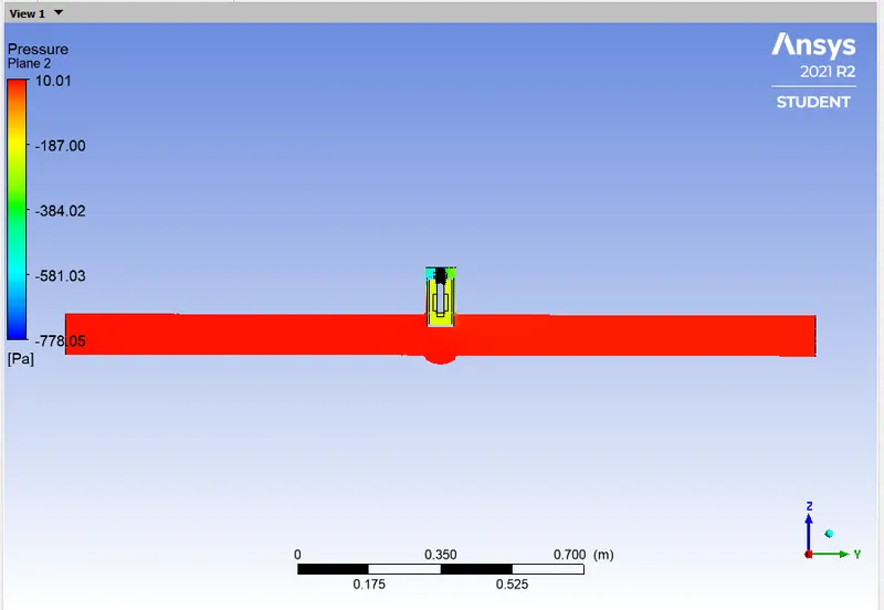
PRESSURE CONTOUR:
CALCULATION:
- Flow Coefficient: `C_v = Q*sqrt((SG)/(triangle P))`
- = `0.14864*15.85*sqrt(1/0.00145038)`
- = 0.14864*15.85*26.258
- = 61.8623
- Flow Factor: `K_v = 0.865*C_v`
- = 0.865*61.8623
- = 53.5109
CASE - 2:
- Gate Opening = 20mm
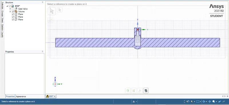
GEOMETRY:
MESHING:
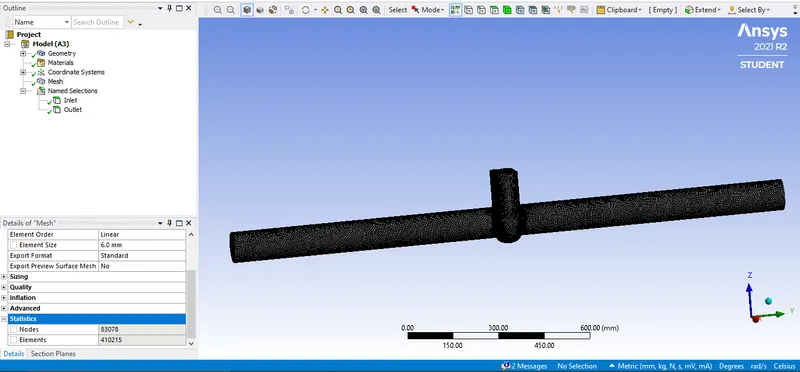
SETUP:
RESULTS:
RESIDUALS:
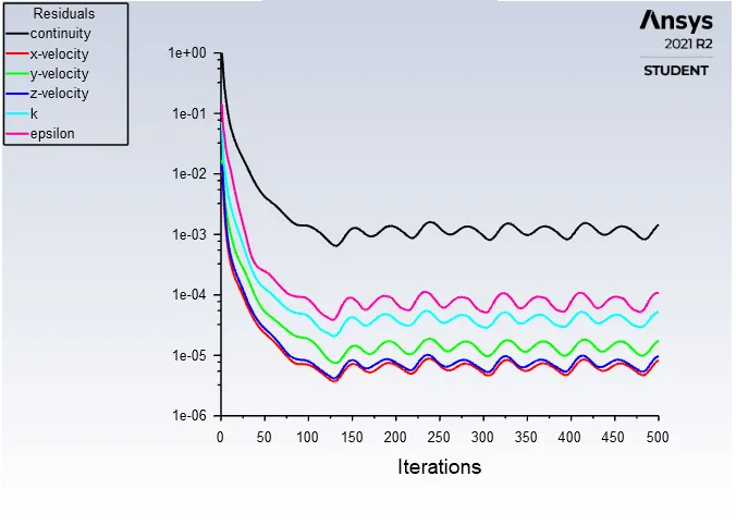
MASS FLOW RATE PLOT:
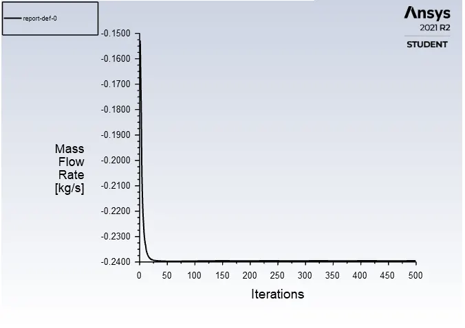

VELOCITY CONTOUR:
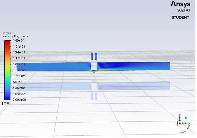

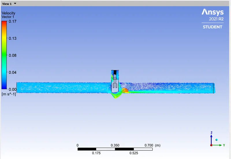
VELOCITY VECTOR:
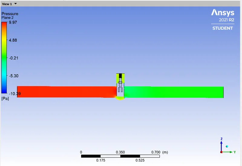
PRESSURE CONTOUR:
CALCULATION:
- Flow Coefficient: `C_v = Q*sqrt((SG)/(triangle P))`
- = `0.23952*15.85*sqrt(1/0.00145038)`
- = 0.23952*15.85*26.258
- = 99.6856
- Flow Factor: `K_v = 0.865*C_v`
- = 0.865*99.6856
- = 86.2280
CASE - 3:
- Gate Opening = 30mm
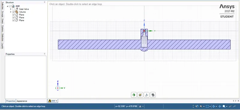
GEOMETRY:
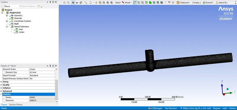
MESHING:
SETUP:
RESULTS:
RESIDUALS:
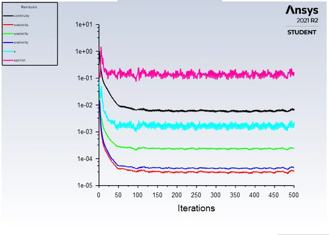
MASS FLOW RATE PLOT:
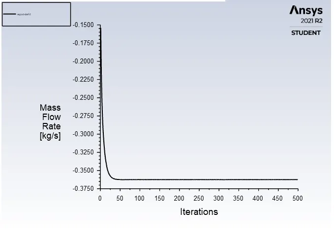

VELOCITY CONTOUR:
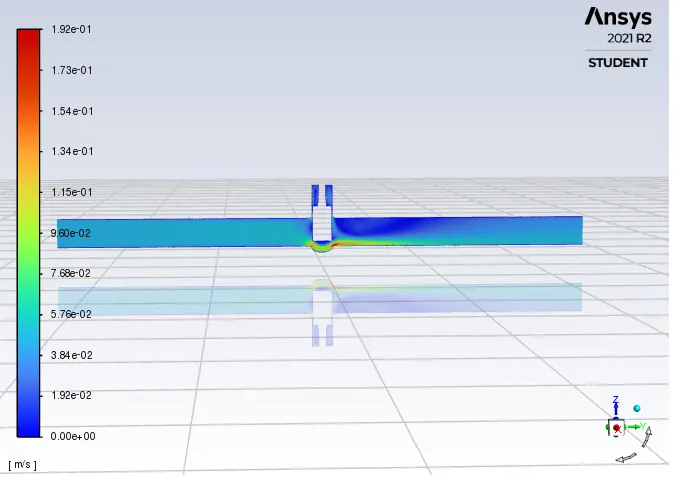
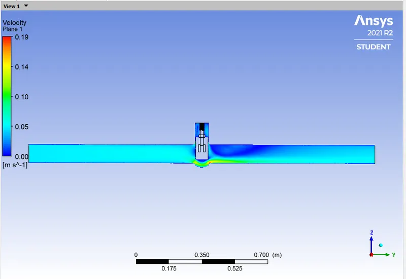
VELOCITY VECTOR:
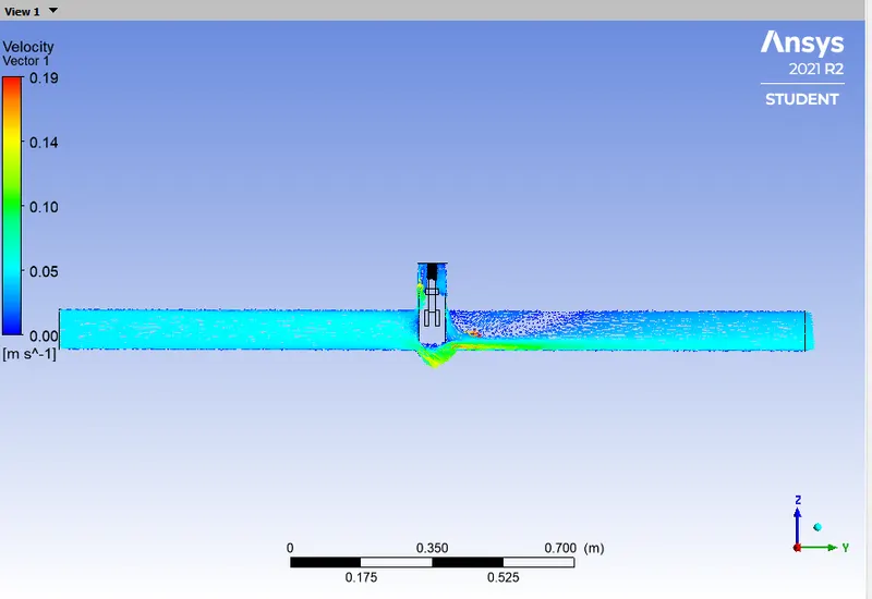
PRESSURE CONTOUR:
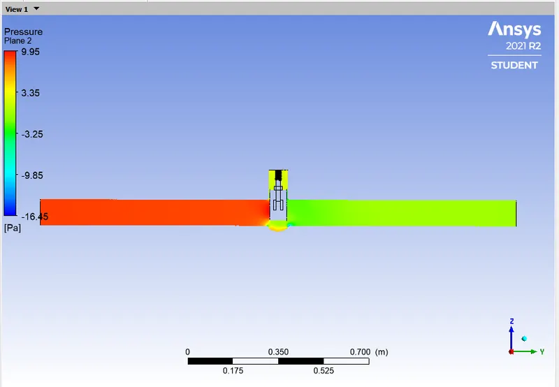
CALCULATION:
- Flow Coefficient: `C_v = Q*sqrt((SG)/(triangle P))`
- = `0.36242*15.85*sqrt(1/0.00145038)`
- = 0.36242*15.85*26.258
- = 150.8353
- Flow Factor: `K_v = 0.865*C_v`
- = 0.865*150.8353
- = 130.4725
CASE - 4:
- Gate Opening = 40mm
GEOMETRY:
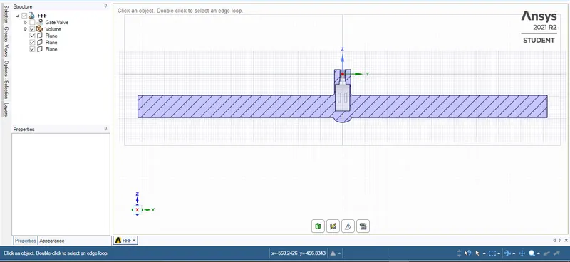
MESHING:
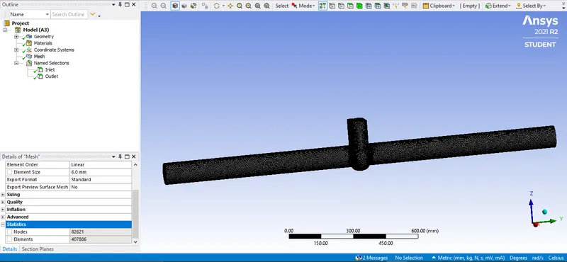
SETUP:
RESULTS:
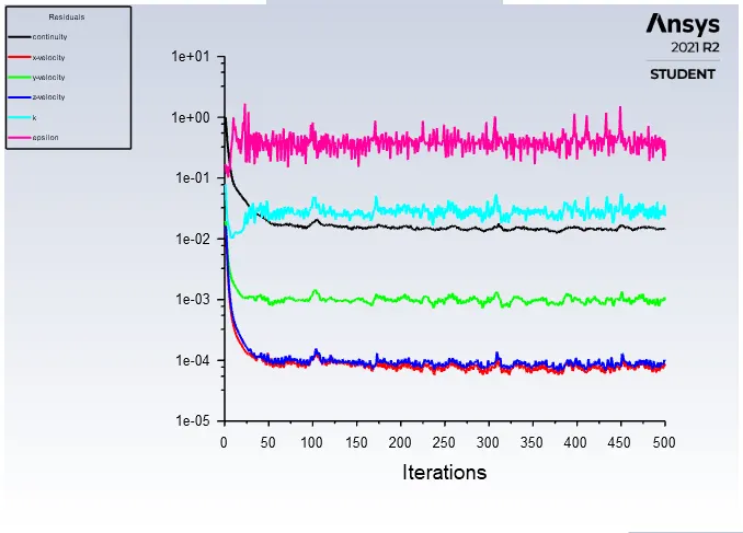
RESIDUALS:
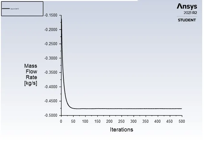
MASS FLOW RATE PLOT:

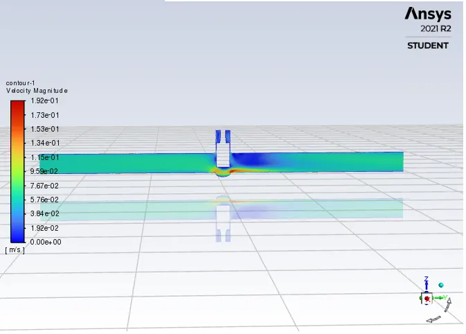
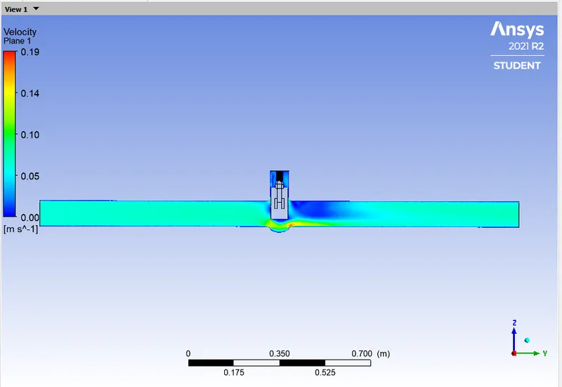
VELOCITY CONTOUR:
VELOCITY VECTOR:
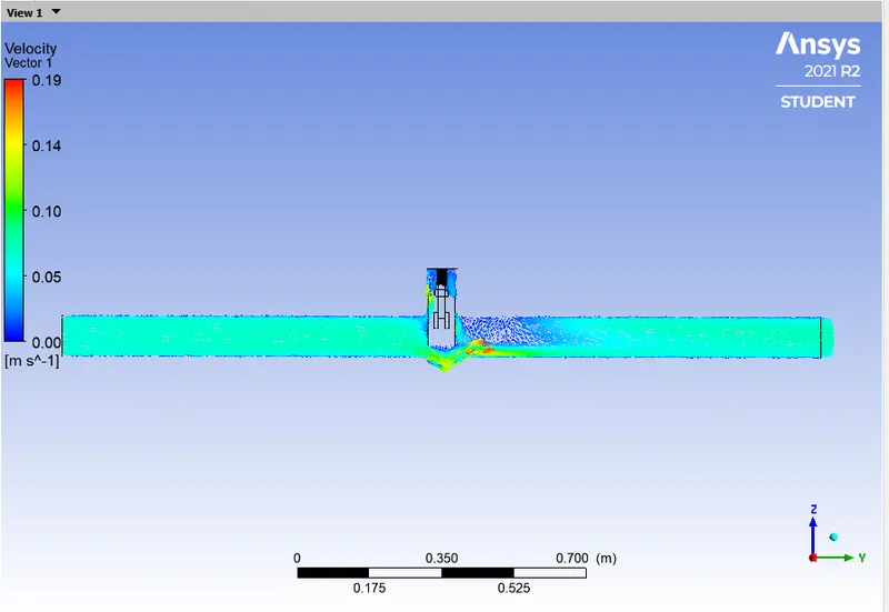
PRESSURE CONTOUR:
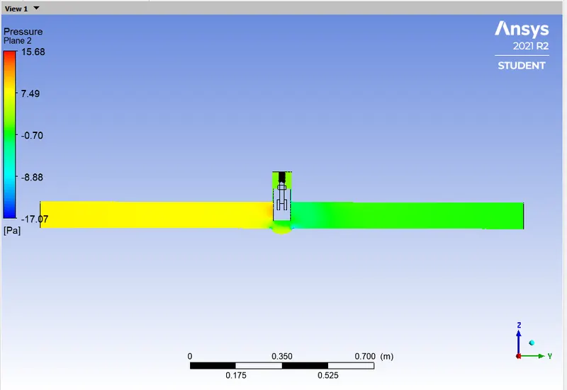
CALCULATION:
- Flow Coefficient: `C_v = Q*sqrt((SG)/(triangle P))`
- = `0.47602*15.85*sqrt(1/0.00145038)`
- = 0.47602*15.85*26.258
- = 198.1144
- Flow Factor: `K_v = 0.865*C_v`
- = 0.865*198.1144
- = 171.3689
CASE - 5:
- Gate Opening = 50mm
GEOMETRY:
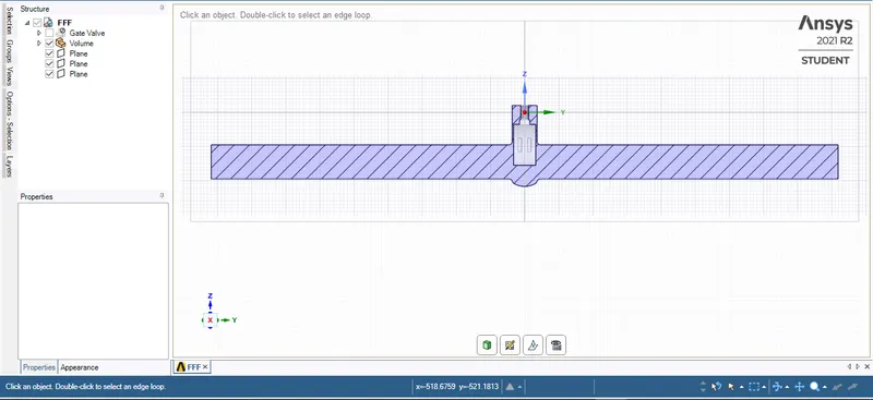
MESHING:
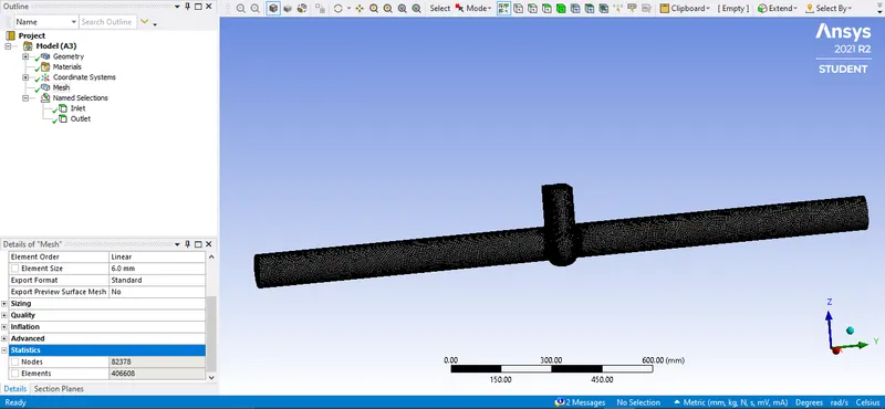
SETUP:
RESULTS:
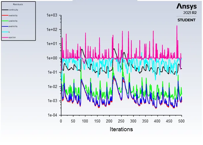
RESIDUALS:
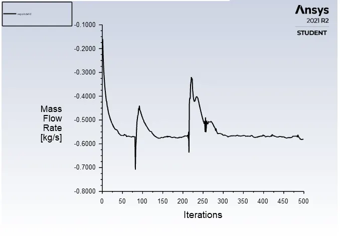
MASS FLOW RATE PLOT:

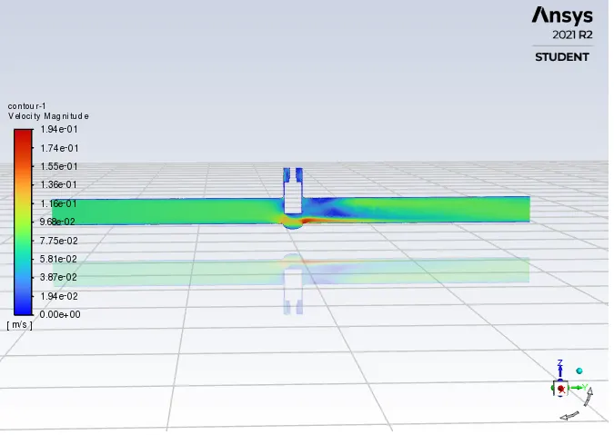
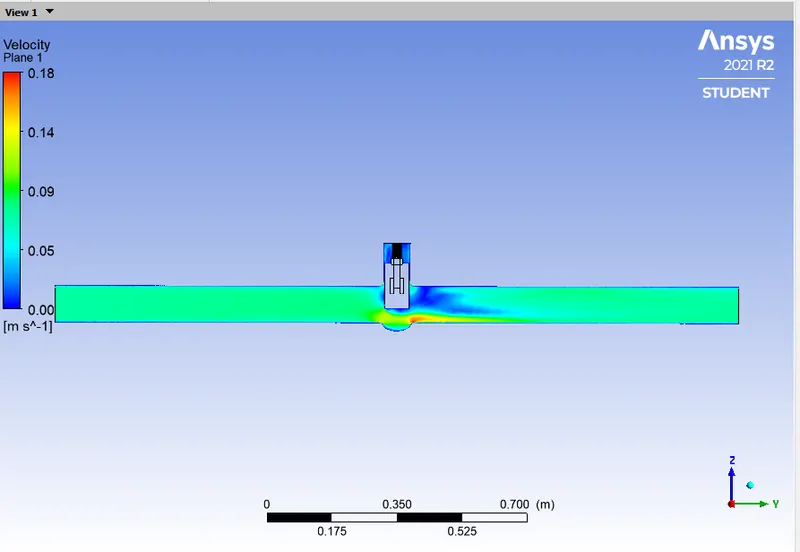
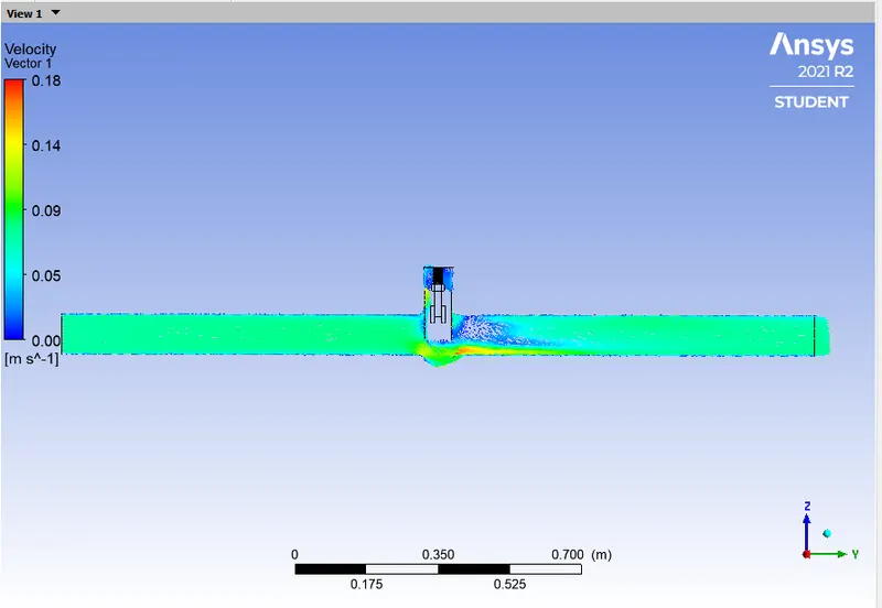
VELOCITY CONTOUR:
VELOCITY VECTOR:
PRESSURE CONTOUR:
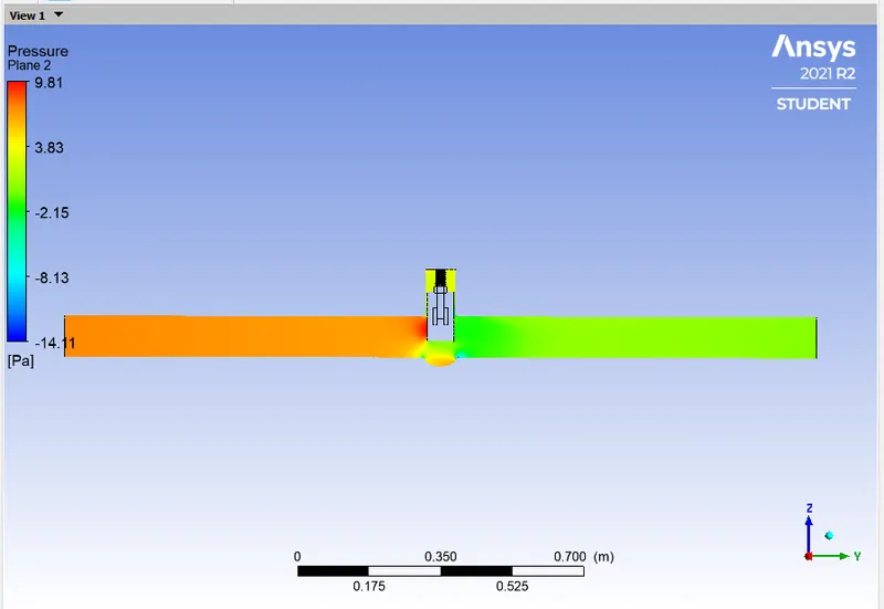
CALCULATION:
- Flow Coefficient: `C_v = Q*sqrt((SG)/(triangle P))`
- = `0.57679*15.85*sqrt(1/0.00145038)`
- = 0.57679*26.258
- = 240.0538
- Flow Factor: `K_v = 0.865*C_v`
- = 0.865*240.0538
- = 207.6465
CASE - 6:
- Gate Opening = 60mm
GEOMETRY:
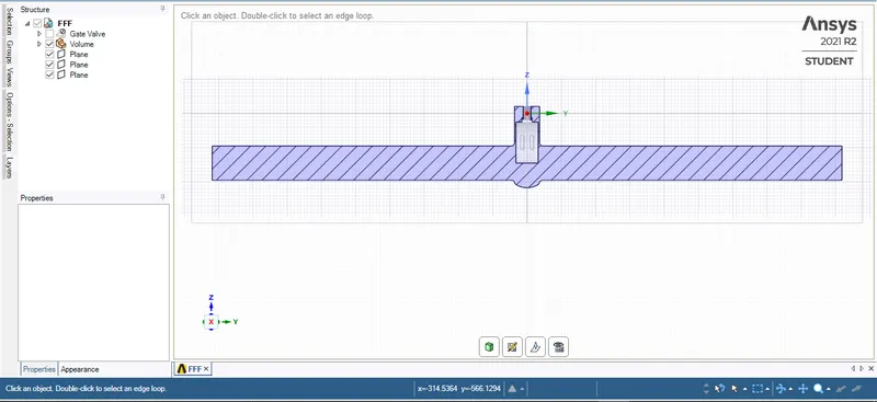
MESHING:
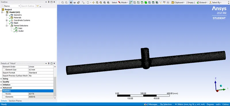
SETUP:
RESULTS:
RESIDUALS:
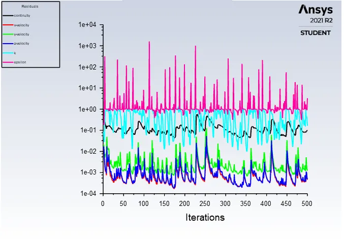
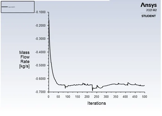
MASS FLOW RATE PLOT:

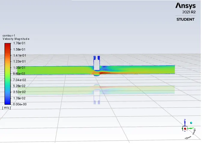
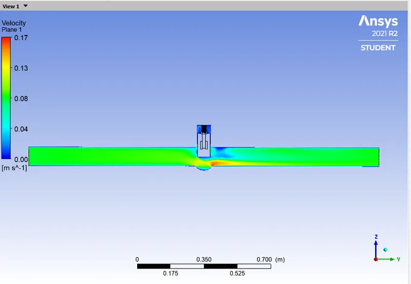
VELOCITY CONTOUR:
VELOCITY VECTOR:
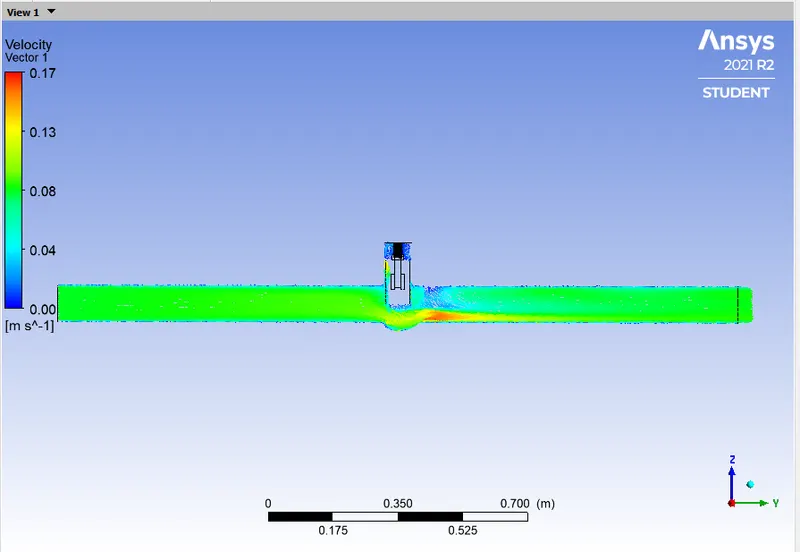
PRESSURE CONTOUR:
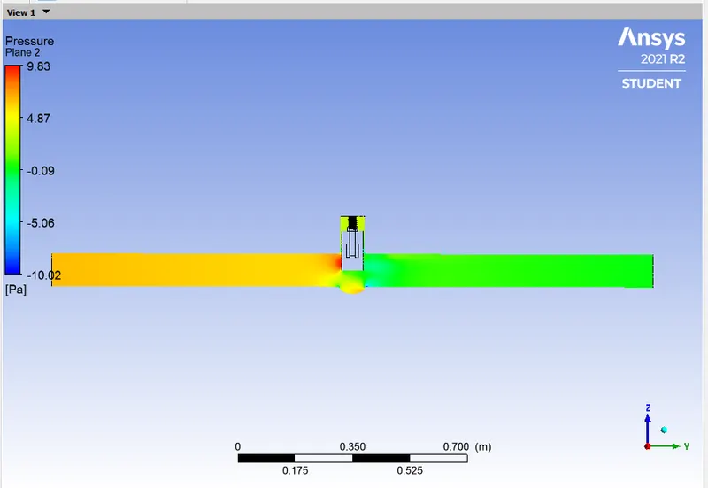
CALCULATION:
- Flow Coefficient: `C_v = Q*sqrt((SG)/(triangle P))`
- = `0.65141*15.85*sqrt(1/0.00145038)`
- = 0.65141*15.85*26.258
- = 271.1098
- Flow Factor: `K_v = 0.865*C_v`
- = 0.865*271.1098
- = 234.5101
CASE - 7:
- Gate Opening = 70mm
GEOMETRY:
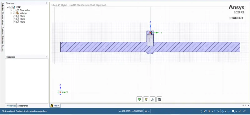
MESHING:
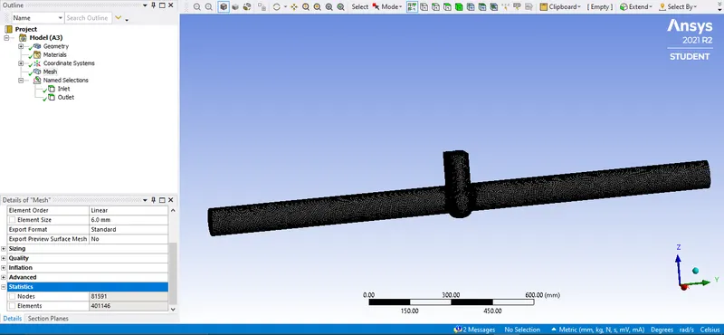
SETUP:
RESULTS:
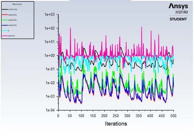
RESIDUALS:
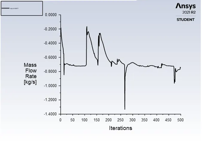
MASS FLOW RATE PLOT:

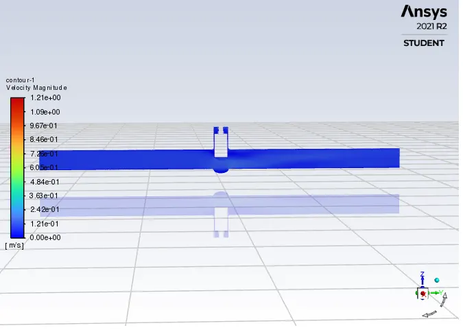
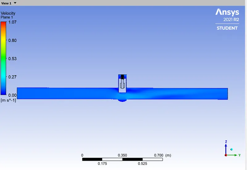
VELOCITY CONTOUR:
VELOCITY VECTOR:
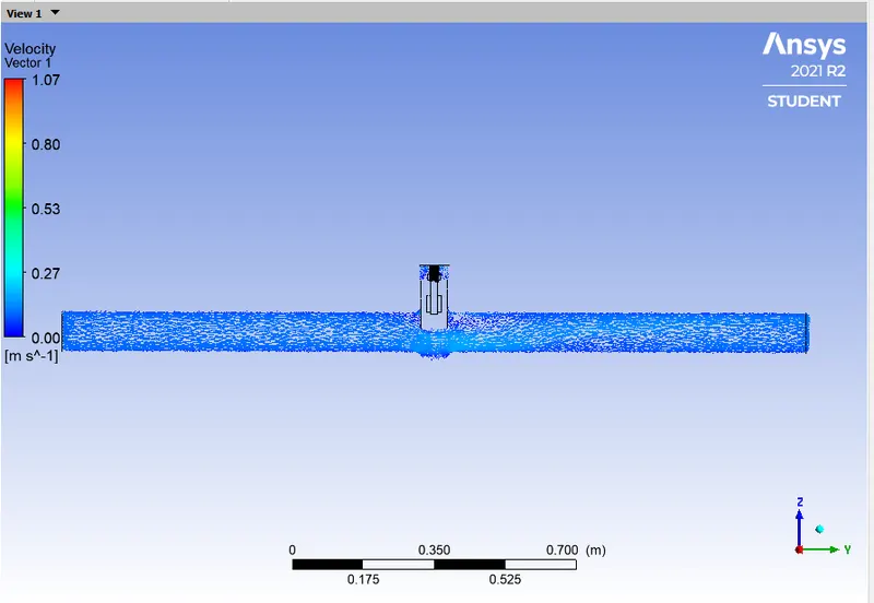
PRESSURE CONTOUR:
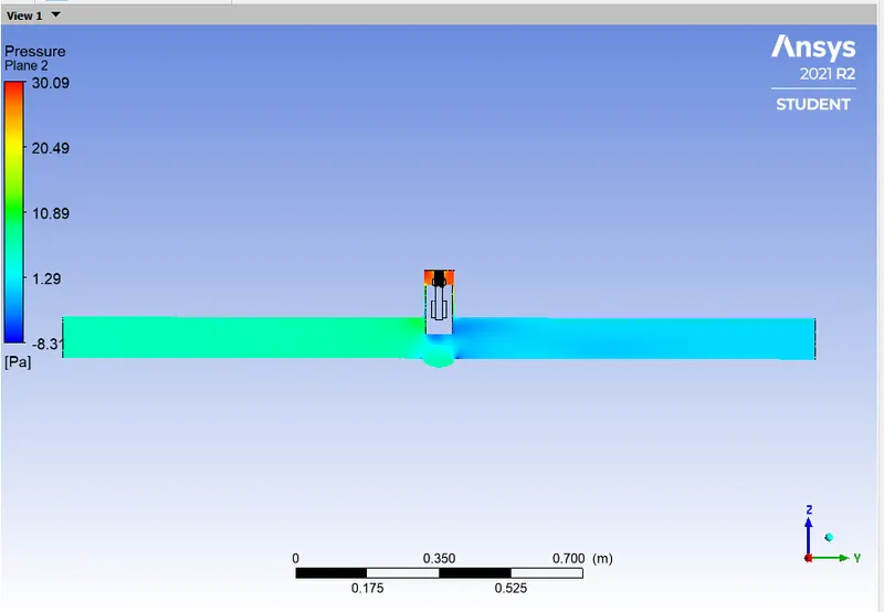
CALCULATION:
- Flow Coefficient: `C_v = Q*sqrt((SG)/(triangle P))`
- = `0.75122*15.85*sqrt(1/0.00145038)`
- = 0.75122*15.85*26.258
- = 312.6497
- Flow Factor: `K_v = 0.865*C_v`
- = 0.865*312.6497
- = 270.4420
CASE - 8:
- Gate Opening = 80mm
GEOMETRY:
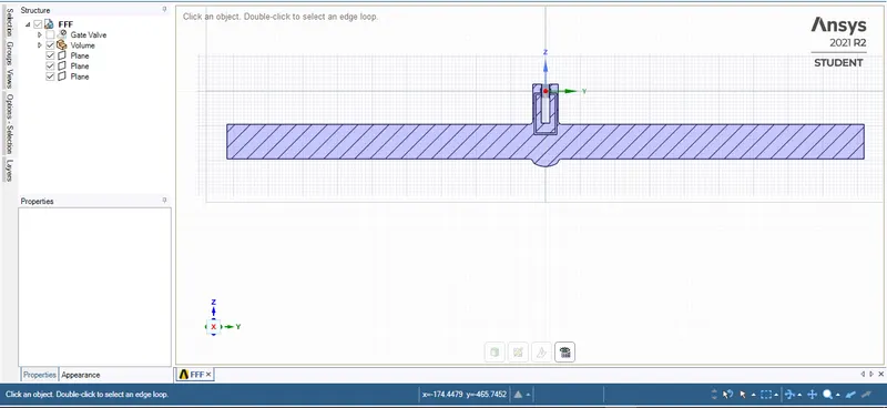
MESHING:
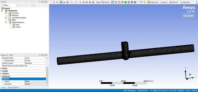
SETUP:
RESULTS:
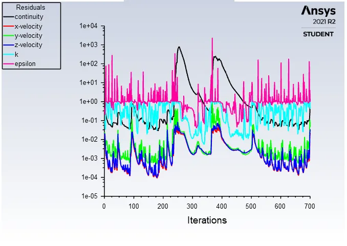
RESIDUALS:
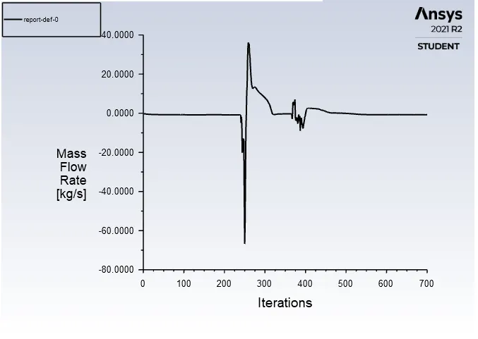
MASS FLOW RATE PLOT:

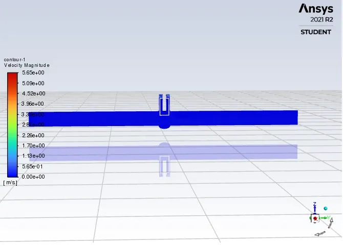
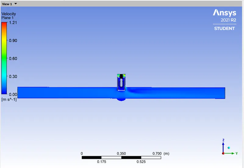
VELOCITY CONTOUR:
VELOCITY VECTOR:
PRESSURE CONTOUR:
CALCULATION:
- Flow Coefficient: `C_v = Q*sqrt((SG)/(triangle P))`
- = `0.78097*15.85*sqrt(1/0.00145038)`
- = 0.78097*15.85*26.258
- = 325.0313
- Flow Factor: `K_v = 0.865*C_v`
- = 0.865*325.0313
- = 281.1521
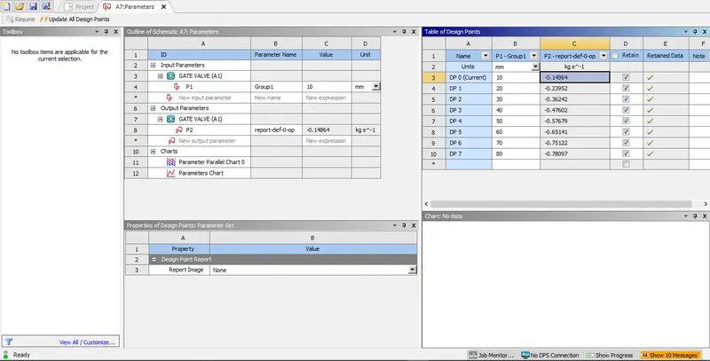
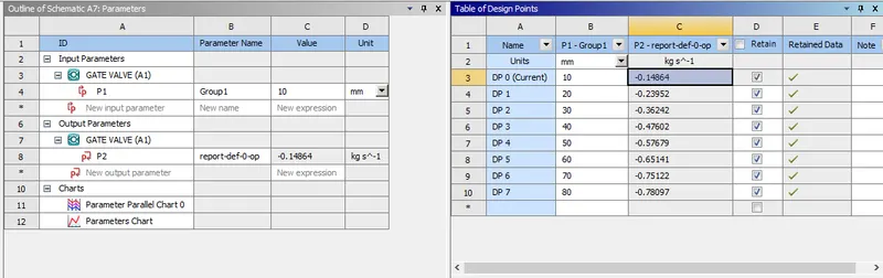
PARAMETER TABLE:
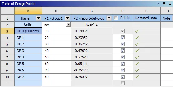
TABULATION:
| SL NO. | OPENING (mm) | MASS FLOW RATE (Kg/s) | FLOW COEFFICIENT (Cv) | FLOW FACTOR (Kv) |
| 01. | 10 | -0.14864 | 61.8623 | 53.5109 |
| 02. | 20 | -0.23952 | 99.6856 | 86.2280 |
| 03. | 30 | -0.36242 | 150.8353 | 130.4725 |
| 04. | 40 | -0.47602 | 198.1144 | 171.3689 |
| 05. | 50 | -0.57679 | 240.0538 | 207.6465 |
| 06. | 60 | -0.65141 | 271.1098 | 234.5101 |
| 07. | 70 | -0.75122 | 312.6497 | 270.4420 |
| 08. | 80 | -0.78097 | 325.0313 | 281.1521 |
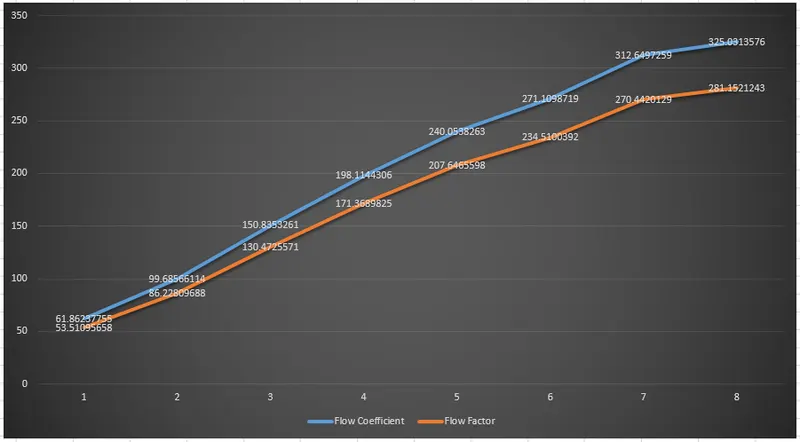
PLOT:
CONCLUSION:
- From the above assignment we performed the flow simulation inside a Gate valve and performed the Parametric Study for the opening from 10% to 20% of the Gate Disc.
- From the above we can observe that as we increase the opening or as we open more of the Gate Disc then the mass flow rate at the outlet increases as because as we increase the opening the resistance to the flow of water or the obstruction decreases which results in increased mass flow of water. As a result, the mass flow rate of water at the outlet increases as we increase the opening of the Gate Disc.
- From the above table we can observe that as we increase the opening of the Gate Disc the mass flow rate at the output increase which increases the Flow Coefficient and the Flow Factor.
- So, we can say that as we increase the mass flow rate the Flow Coefficient and the Flow Factor increases.