Week 9 - Parametric study on Gate valve.
Parametric study on Gate valve.
Gate Valve :
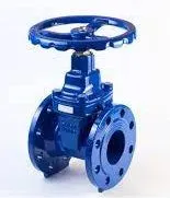
A gate valve is also known as a sluice valve, is a valve that opens by lifting a barrier (gate) out of the path of the fluid. Gate valves require very little space along the pipe axis and hardly restrict the flow of fluid when the gate is fully opened. The gate faces can be parallel but are most commonly wedge-shaped (in order to be able to apply pressure on the sealing surface).
Construction :
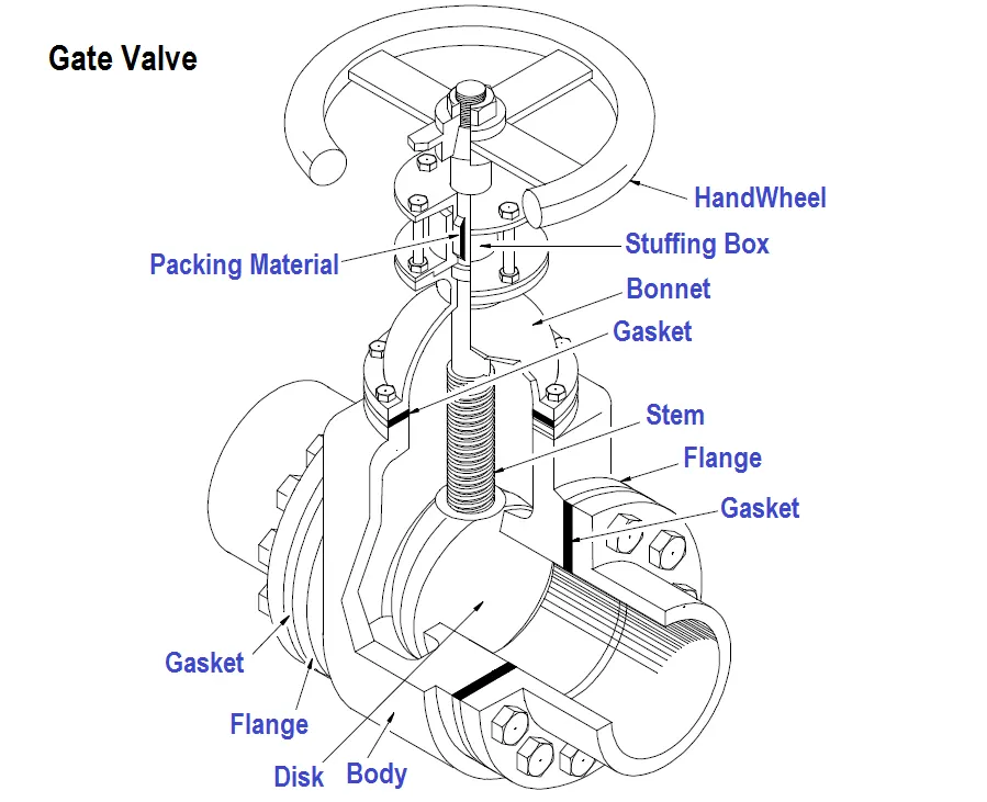
Common gate valves are actuated by a threaded stem that connects the actuator to the gate. They are characterized as having either a rising or a non-rising stem, depending on which end of the stem is threaded. Rising stems are fixed to the gate and rise and lower together as the valve is operated, providing a visual indication of valve position. The actuator is attached to a nut that is rotated around the threaded stem to move it. Non-rising stem valves are fixed to, and rotate with, the actuator, and are threaded into the gate. They may have a pointer threaded onto the stem to indicate valve position since the gate's motion is concealed inside the valve. Non-rising stems are used where vertical space is limited.
Gate valves may have flanged ends drilled according to pipeline-compatible flange dimensional standards.
Gate valves are typically constructed from cast iron, cast carbon steel, ductile iron, gunmetal, stainless steel, alloy steels, and forged steel.
Advantages:-
- Available in large sizes
- Can be used with slurries and viscous liquids
- Used as a shut off valve
- Easy to maintain and disassemble
- Bidirectional & Inexpensive
- Inherently fire-safe (when used with a metal sheet)
Disadvantages:-
- Low-pressure limitations
- Slow open and close time
- Erosion of the seat and disk can occur
- Poor throttling characteristics
- Difficult to repair
- Should not be used in sanitary applications
Applications:-
- Gate valves are used in many industrial applications including the oil and gas industry, pharmaceuticals, manufacturing, automotive, and marine.
- Non-rising stem gate valves are very popular on ships, in underground applications, or where vertical space is limited because they don't take up extra space. Gate valves can be used in demanding environments such as high-temperature and high-pressure environments. They are often seen in power plants, water treatments, mining, and offshore applications.
----------------------------------------------------------------------------------------------------------------------
Parametric Study: -
A parameter is a numerical or other measurable factor that help to define a particular system. A parameter is linked to a data model property within an application. You can have input and output parameters. Parameter values can be numeric or non-numeric (string or Boolean). Non-numeric parameters are ignored for charting purposes. An input parameter can be modified at the project level and drives a change within the data model. The value of an output parameter is set by the application, based on the current results or state.
- Input parameters define the geometry or inputs to the analysis for the system under investigation. Input parameters have predefined values or ranges that may be changed. These include CAD parameters, analysis parameters, and DesignModeler parameters. CAD and DesignModeler input parameters include length and radius. Analysis input parameters include pressure, material properties, and sheet thickness.
- Output parameters result from the geometry or are the response outputs from the analysis. These include volume, mass, frequency, stress, velocities, pressures, forces, and heat flux.
Custom Parameters are project-level parameters that are not directly associated with a data model property. They can be a custom input or custom output parameter that is defined by a constant value, such as `sin(pi/2)` Or, they can be a derived parameter, defined by an expression of other parameters, such as`P2+3*P3.` For more information, see Expressions, Functions, Quantities, and Units.
All parameters have a quantity, preferably with a quantity name. The quantity name is used to define preferred and available units for the quantity. If the value does not have a quantity name defined, Workbench displays the value without units.
You can add parameters to or delete them from the current project. However, this may set existing design points and design exploration systems to an out-of-date state and can result in several hours of recalculation time, depending on the project. Be aware that deleting a parameter referenced in the expression of another parameter invalidates the driven data model, resulting in an error.
-
Negative dimension values can invert the direction vector of SpaceClaim operations with which they are associated. This change is applied to the current and subsequent design point updates. As a result, when a Workbench input parameter is used as a driving dimension for a SpaceClaim geometry, negative dimension values can result in unexpected geometric changes.
-
When dimensional geometry parameters are imported into Workbench from SpaceClaim or a bi-directional CAD interface, design point updates may fail when dependencies exist between the parameters or when the parametric update in the CAD system or SpaceClaim cannot be realized with the parameter values specified in Workbench.
Flow coefficient:-
The flow coefficient of a device is a relative measure of its efficiency at allowing fluid flow. It describes the relationship between the pressure drop across an orifice valve or other assembly and the corresponding flow rate.
Mathematically the flow coefficient `C_v` can be expressed as :
`C_v = Q*sqrt((SG)/(triangle P))`
where:
- `Q` = Rate of flow (expressed in US gallons per minute),
- ` SG` = Specific gravity of the fluid (for water = 1),
- `triangleP`= Pressure drop across the valve (expressed in psi).
The metric equivalent flow factor (Kv; commonly used everywhere else in the world with the exception of the United States) is calculated using metric units :
- `C_v = Q*sqrt((SG)/(triangle P))`
where:
- `K_v` = Flow factor (expressed in `m^{3}.h^{-1}`).
- `Q` = Flowrate (expressed in cubic metres per hour `m^{3}/h`),
- ` SG`= Specific gravity of the fluid (for water = 1),
- `triangleP` = Pressure difference across the device (expressed in [bar]).
`K_v` can be calculated from `C_v` using the equation:
- `K_v=0.865*C_v`
Procedure:-
- Geometry preparation
- Meshing
- Setup & Solution
- Results
----------------------------------------------------------------------------------------------------------------------
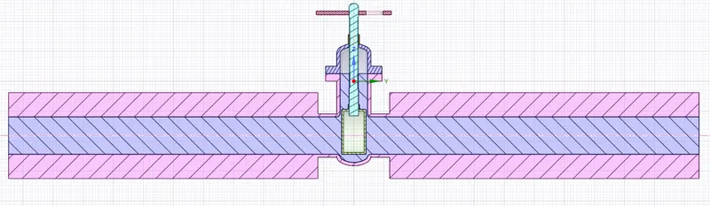
1. Geometry preparation:
- Open Spaceclaim and import the Gate valve 3-D model.
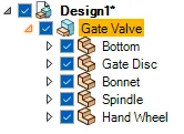
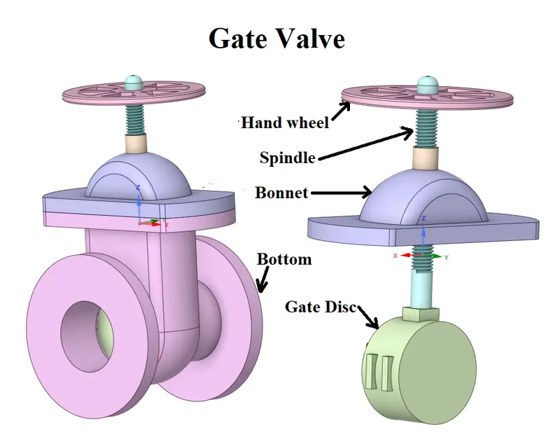
- Hide the bottom
- Parameterising Gate Disc lift:
- Design => Move
- Move Component select Gate Disc
- The coordinate system will appear on the body Pull the Green co-ordinate axis towards the top of the spindle.
- Enter value = 10 mm.
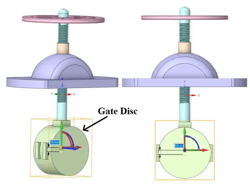
- If you see `P` beside Value enter Press to parameterize the raise of the gate disc.
- An alternate way to parameterize the Gate Disc raise.
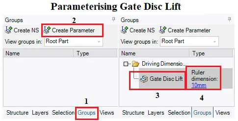
- Go to the Groups menu which is adjacent to the Structure menu
- In the Group menu, you will be able to see the Create Parameter button, which will be enabled only after you have moved the gate disc.
- Click on the Create Parameter following which you will see a Group-1 appear in which you can edit the dimensions of the lift.
- Edit Group-1 name to Gate Disc Lift
- Move Component select Gate Disc
- Design => Move
- Extending the coupling sides of the bottom which will act as inlet and outlet pipe.
- Design => Pull
- Select Inlet face and pull up to 800 mm.
- Select Outlet face and pull up to 800 mm.
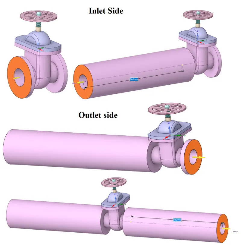
- Design => Pull
- Use the Volume extract command to extract the Fluid domain.
- Volume extract
- Hide Bonnet for better selection of top boundary
- Edge selection(Select boundaries)
- Create volume Enclosure from the selected boundaries
- Fluid domain extracted.
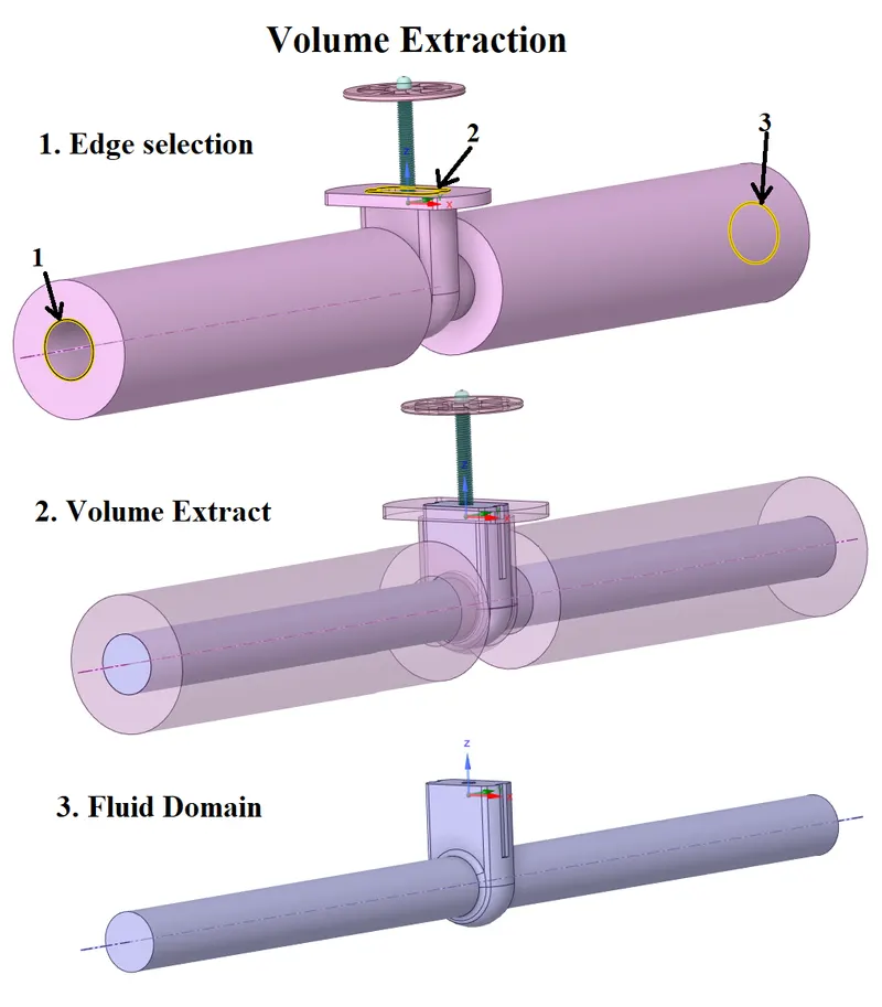
- Create volume Enclosure from the selected boundaries
- Section View:-
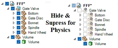
- Hide all Gate valve components and suppress them for physics so that they are not going to participate in the calculation part.
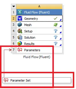
- Conforming Parameterized Gate Disc Lift with Workbench.
----------------------------------------------------------------------------------------------------------------------
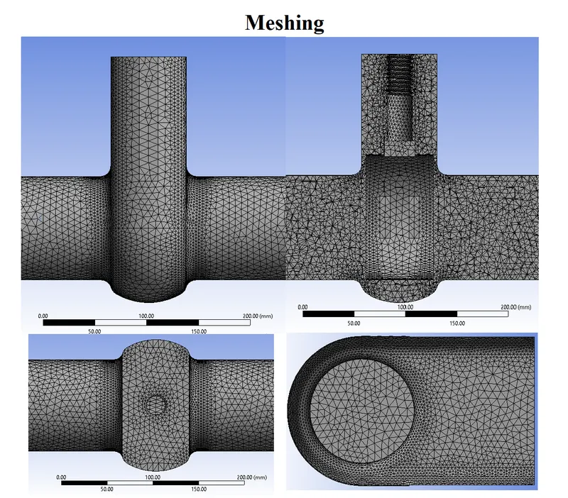
2. Meshing:
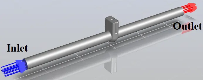
- Creating Named Sections:
- Inlet
- Outlet
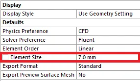
- Generate Mesh with element size = 7 mm
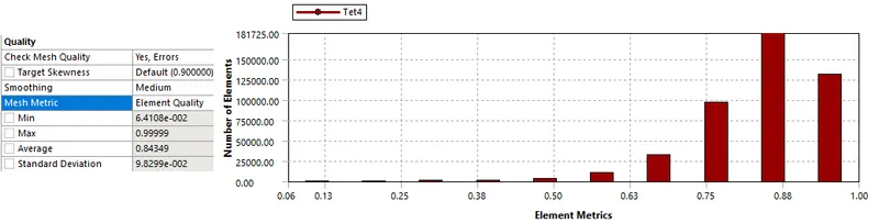
- Element Quality:
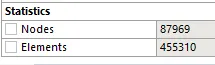
- Statistics:

----------------------------------------------------------------------------------------------------------------------
3. Setup & Solution:-
- Double Precision, Solve processers = 4.
- Solver
- Type = Pressure Based
- Velocity Formulation = Absolute.
- Time= Steady
- Velocity Formulation = Absolute.
- Type = Pressure Based
- Gravity = on
- `Z =−9.81m/s^2`
- Materials:
- Water
- Density :- `998.2 [Kg/m^3]`
- Viscosity :- `0.001003 [(Kg)/(m-s)]`
- Water
- Cell zone conditions:-
- material name = Water
- Boundary conditions:-
- Typically for pipe flows 10-pascal pressure is acceptable.
-
Type Momentum Inlet Pressure inlet Guage Total pressure = 10 [Pa] Outlet Pressure Outlet Guage Total pressure = 0 [Pa] Wall Motion Shear Condition Wall Stationary Wall No-slip
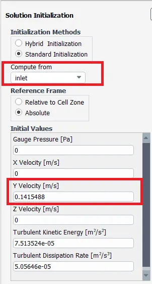
- To find the type of viscous model we need to calculate Renolds number but in this problem, we used inlet type as pressure inlet of 10 Pascal.
- To know the inlet velocity go to the
- initialization => Standard Initialization
- Compute from => Inlet
- where you can find the inlet velocity magnitude.
- Reynolds Number Calculation
- `R_e = (rho*V*D)/mu`
- `text(Density of water ) rho = 998.2 (Kg)/m^3`
- `text(Inlet Velocity ) V = 0.1415488 m/s`
- `text(Pipe Dia ) D = 0.1 m`
- `text(Viscosity ) mu = 0.001003 [(Kg)/(m-s)]`
- `R_e = text(998.2 * 0.1415488 * 0.1)/0.001003 = 14087.1397 > 2000`
- `R_e` is Greater than 2000 so we can go for Turbulent viscous model.
- `R_e = (rho*V*D)/mu`
- Reynolds Number Calculation
- To know the inlet velocity go to the
- Viscous model
- k-Epsilon
- Realizable
- Scalable Wall Functions.
- Realizable
- k-Epsilon
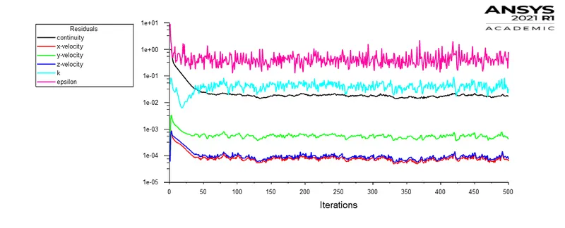
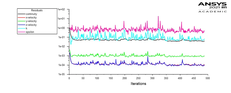
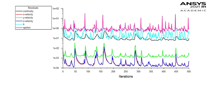
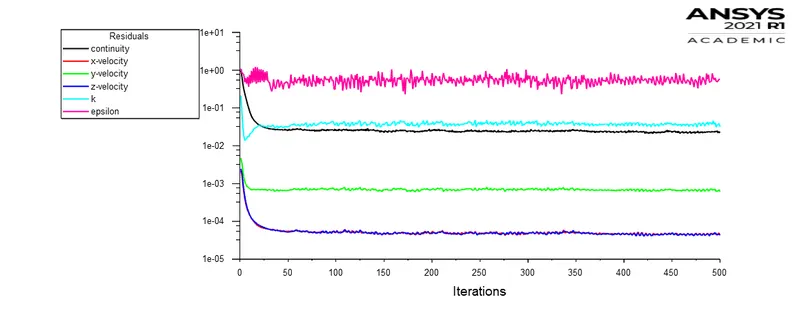
- Residual monitors:
- uncheck the convergence
- Report Definitions:-
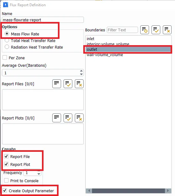
- New Report => Flux report definitions
- Mass Flowrate report
- Boundary => Outlet
- Create
- Report File
- Report Plot
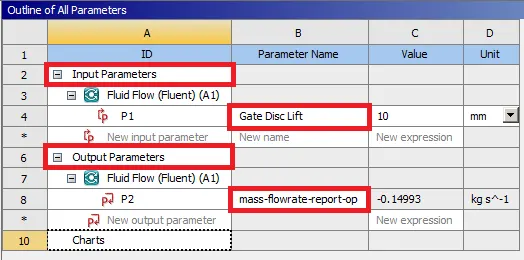
- Output Parameter
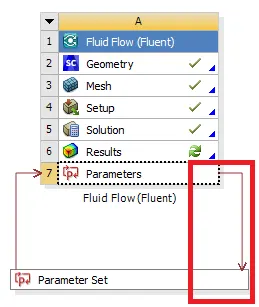
- By Enabling the output parameter calculation result gets updated to the workbench.
- New Report => Flux report definitions
- Initialization methods:-
- Standard Initialization
- Compute from = Inlet.
- Standard Initialization
- Contours and Animations:-
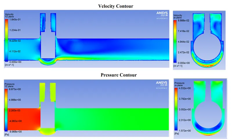
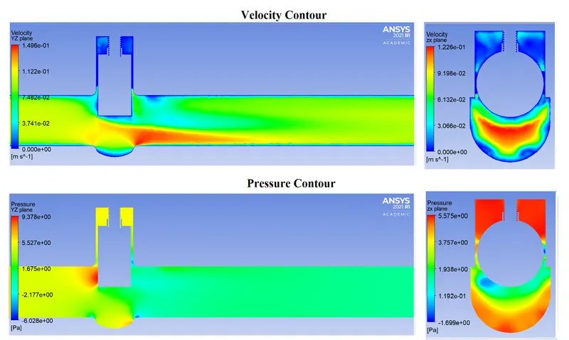
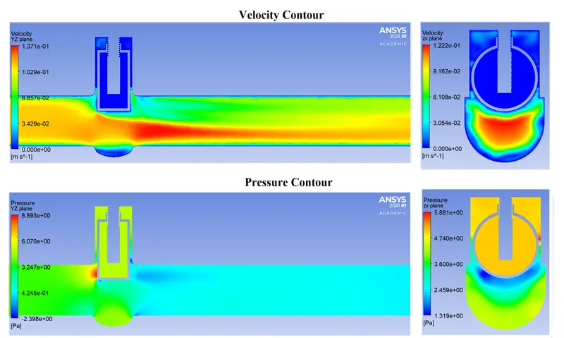
- To plot velocity and pressure contours, we need a plane surface.
- Create => Plane
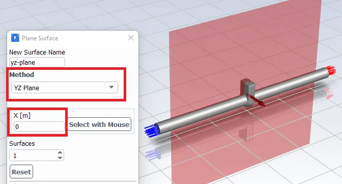
- Create Velocity and pressure contours on the above plane.
- To plot velocity and pressure contours, we need a plane surface.
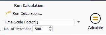
- Run Calculations:-
- Steady-State Simulation
- Steady-State Simulation
----------------------------------------------------------------------------------------------------------------------
4. Parameters & Design Point setting:-
- Parameters:-
- Design Points Calculation:
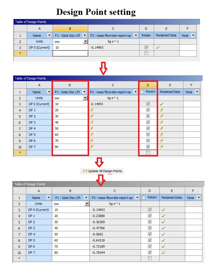
- Parametric study on the gate valve simulation by setting the opening from 10 % to 80%.
- Pipe Diameter = 100 mm
-
Design Point
Opening Percentage (%)
Gate Disc Lift (mm)
0 10% 0.1*100 10 mm 1 20% 0.2*100 20 mm 2 30% 0.3*100 30 mm 3 40% 0.4*100 40 mm 4 50% 0.5*100 50 mm 5 60% 0.6*100 60 mm 6 70% 0.7*100 70 mm 7 80% 0.8*100 80 mm
-
- Design point setting:-
- Add Design points by entering magnitudes in the input section.
- Enable the retain option so that each saves individually.
- Before Updating All Design Points open Spaceclaim and unhide all bodies. so, that we will not get any issues while updating calculation for each design point movement.
----------------------------------------------------------------------------------------------------------------------
5. Results:-
-
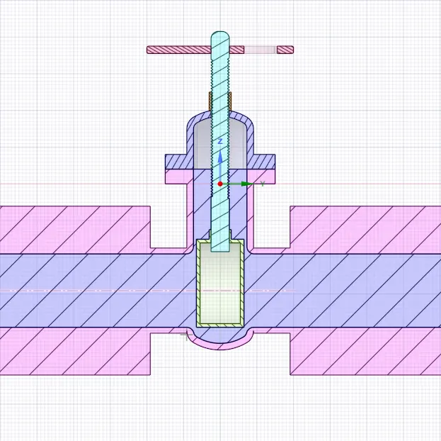
Design Point = 0 10 % Opening Lift = 10 mm -
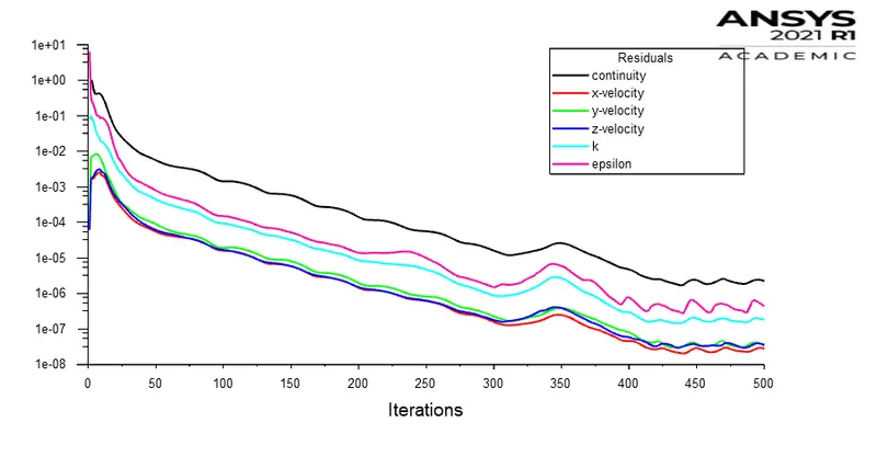
-
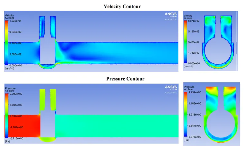
- ----------------------------------------------------------------------------------------------------------------------
-
-
Design Point = 1 20 % Opening Lift = 20 mm 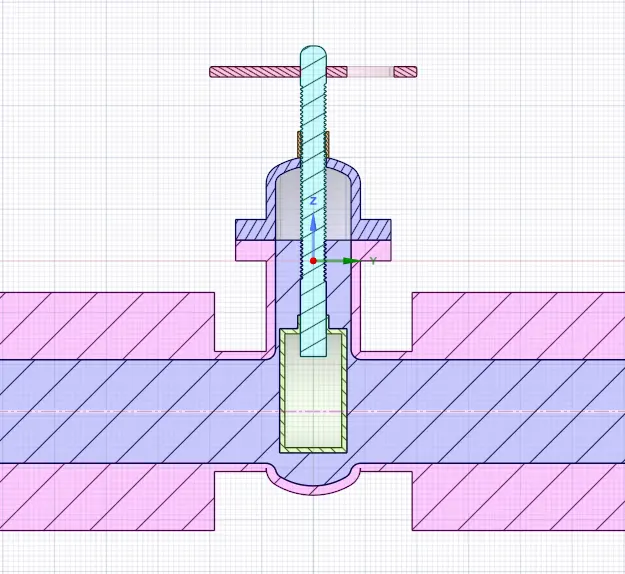
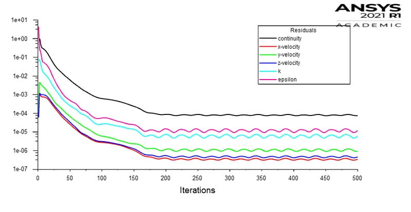
- ----------------------------------------------------------------------------------------------------------------------
-
Design Point = 2 30 % Opening Lift = 30 mm 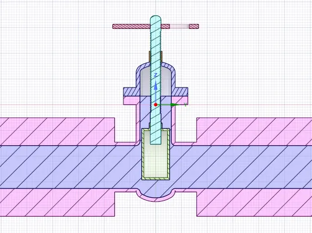
- ----------------------------------------------------------------------------------------------------------------------
-
Design Point = 3 40 % Opening Lift = 40 mm 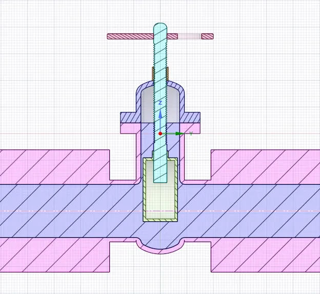
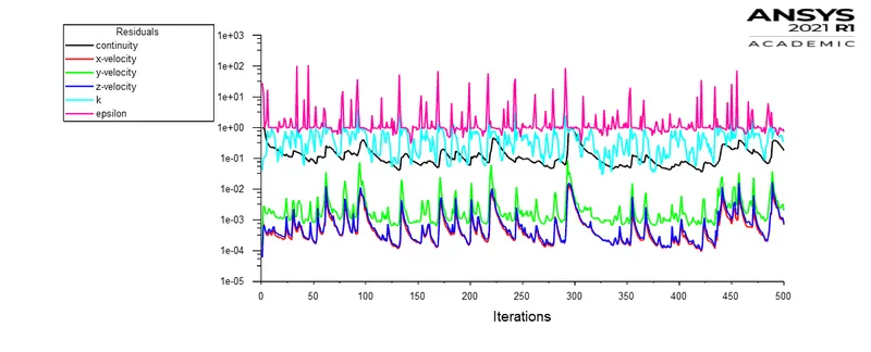
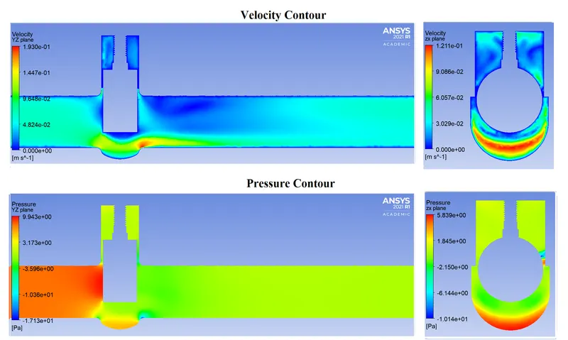
- ----------------------------------------------------------------------------------------------------------------------
-
Design Point = 4 50 % Opening Lift = 50 mm 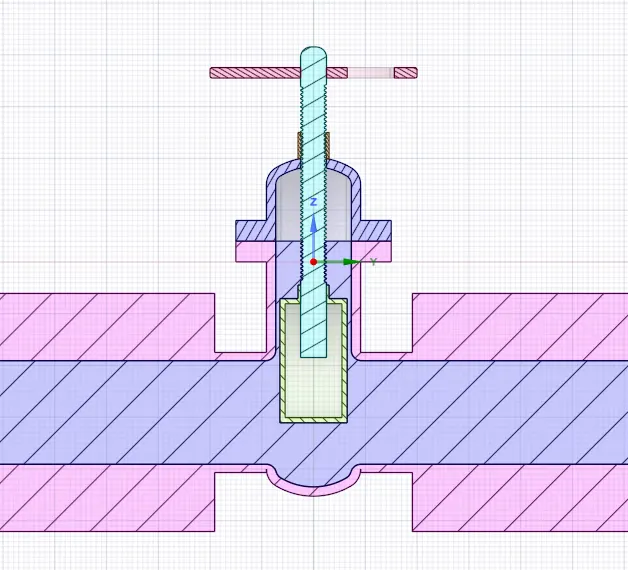
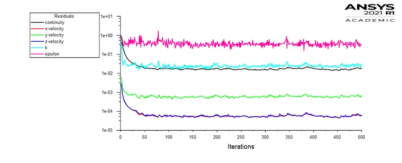
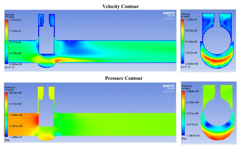
- ----------------------------------------------------------------------------------------------------------------------
-
Design Point = 5 60 % Opening Lift = 60 mm 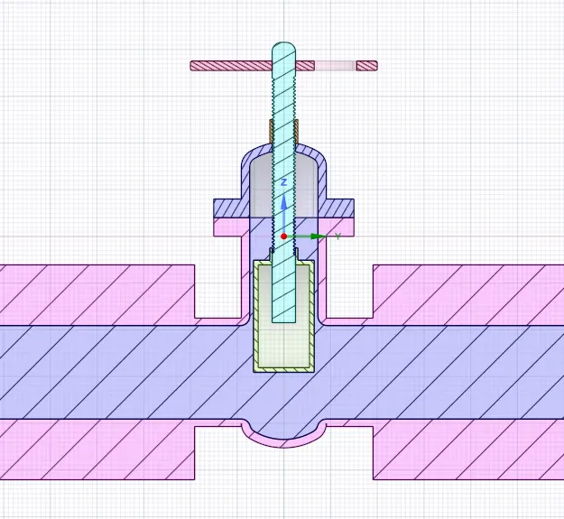
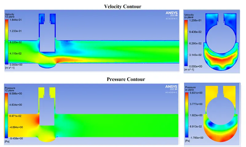
- ----------------------------------------------------------------------------------------------------------------------
-
Design Point = 6 70 % Opening Lift = 70 mm 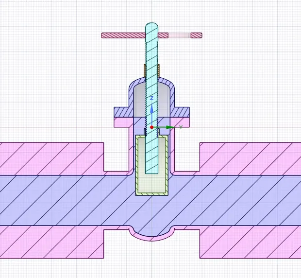
- ----------------------------------------------------------------------------------------------------------------------
-
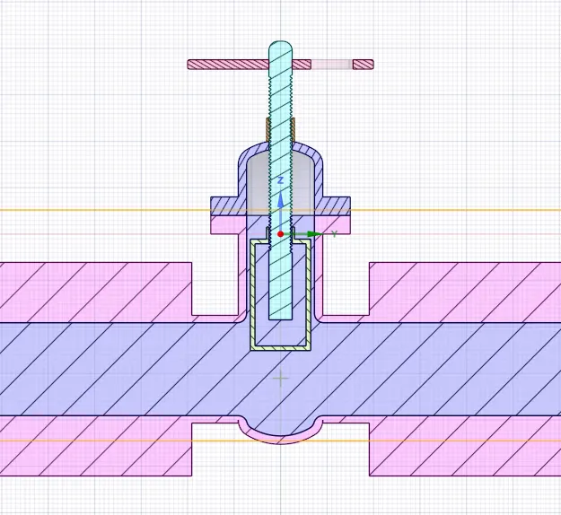
Design Point = 7 80 % Opening Lift = 80 mm
----------------------------------------------------------------------------------------------------------------------
For all the cases
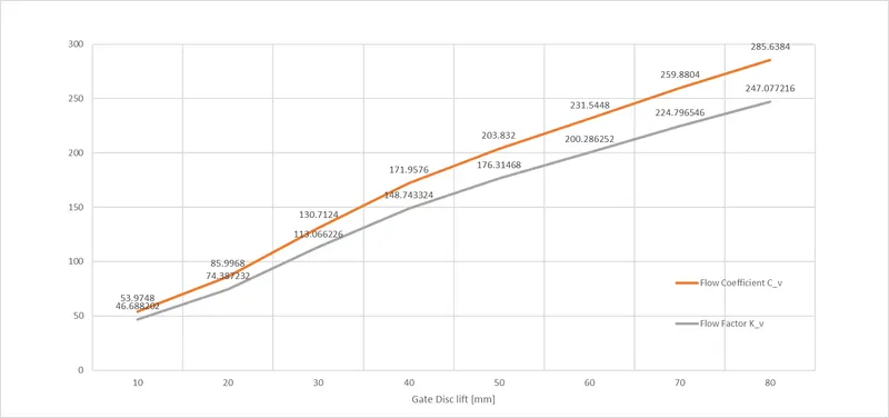
- Flow Coefficient
- `C_v = Q*sqrt((SG)/(triangle P))`
- Flow Factor
- `K_v=0.865*C_v`
- ` SG`= Specific gravity of the fluid =`1000/9898.2 ~= 1`
- `triangleP` = Pressure drop across the device = 10 pascal
- 1 Pascal = 1e-5 Bar
- `Q = text(Flow rate) (kg)/s`
- 1 kilogram (water mass) per second to cubic meters per hour = 3.60 m3/h
Result Table:
| Design Point |
Gate Disc Lift `(mm)` |
Mass Flow rate `(Kg/s)` | Mass Flow rate `(m^3/h)` `[text(1Kg[water mass])]/s = 3.6 m^3/h` | Specific gravity of Water | Pressure Drop [Pa] | Pressure Drop [Bar] 1Pascal = 1e-5 Bar | Flow Coefficient `C_v = Q*sqrt((SG)/(triangle P))` | Flow Factor `K_v = 0.865*C_v` |
| 0 | 10 | 0.14993 | 0.539748 | 1 | 10 | 0.0001 | 53.9748 | 46.6882 |
| 1 | 20 | 0.23888 | 0.859968 | 1 | 10 | 0.0001 | 85.9968 | 74.38723 |
| 2 | 30 | 0.36309 | 1.307124 | 1 | 10 | 0.0001 | 130.7124 | 113.0662 |
| 3 | 40 | 0.47766 | 1.719576 | 1 | 10 | 0.0001 | 171.9576 | 148.7433 |
| 4 | 50 | 0.5662 | 2.03832 | 1 | 10 | 0.0001 | 203.832 | 176.3147 |
| 5 | 60 | 0.64318 | 2.315448 | 1 | 10 | 0.0001 | 231.5448 | 200.2863 |
| 6 | 70 | 0.72189 | 2.598804 | 1 | 10 | 0.0001 | 259.8804 | 224.7965 |
| 7 | 80 | 0.79344 | 2.856384 | 1 | 10 | 0.0001 | 285.6384 | 247.0772 |
Plots:-
- Flow Coefficient & Flow Factor Vs Gate Lift
- Flow Coefficient & Flow Factor Vs Gate Lift
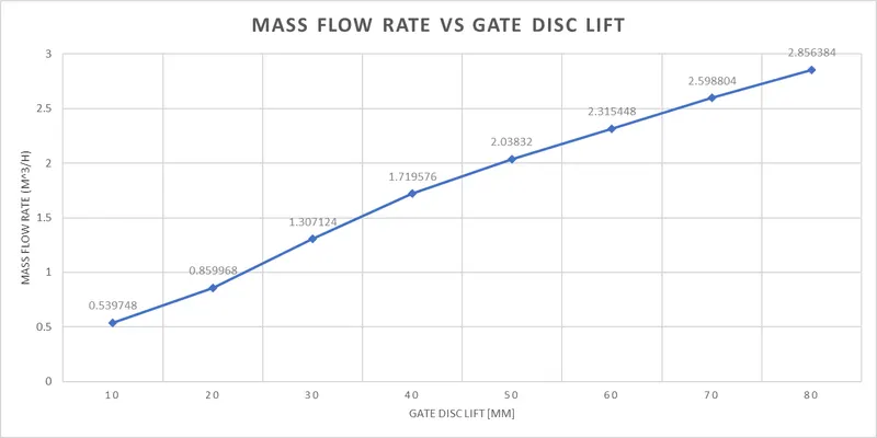
Conclusions:
- Successfully simulated & analyzed parametric study on Gate valve.
- As the Gate Valve lift Increases Mass flow rate at the outlet and the Flow Coefficient increase.