Week 9 - Parametric study on Gate valve.
AIM: Parametric study on Gate valve.
OBJECTIVE:
- To perform a parametric study on the gate valve simulation by setting the opening from 10% to 80%.
- To obtain the mass flow rates at the outlet for each design point.
- To calculate the flow coefficient and flow factor for each opening and plot the graph.
THEORY:
Gate Valve:
Gate valves are valves that operate by lifting a round or rectangular gate out of the path of the fluid. This valve facilitates only unidirectional flow, but unlike globe valves, they give a full bore flow to the fluid. The round or wedge-shaped ring is known as a gate as it moves in a perpendicular direction to the flow of the fluid.
A gate valve controls the media's flow by lifting the gate (open) and lowering the gate (closed). A gate valve's distinct feature is the straight-through unobstructed passageway, which induces minimal pressure loss over the valve. The unobstructed bore of a gate valve also allows for a pig's passage in cleaning pipe procedures, unlike butterfly valves.
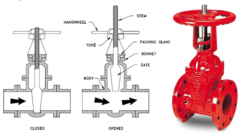
Construction:
Body:
The valve body is the main pressure-retaining part, which also holds other parts named as disc and stem. This also provides passage to flow from the valve, its end connection is piping this end can be but welding type, threaded, and many more depending upon the size and pressure of the piping system. The valve body can be cast, forge in different materials such as cast steel, stainless steel, and alloy steel depending upon the requirement.
Bonnet:
The bonnets of gate valves are made of cast iron and thus require extra care during overhauling. The valves or the gates are circular or wedge-shaped discs and are attached to a threaded spindle working in a nut. The salient feature of gate vales is that the sealing surfaces between the seat and the valve are planer. The vales and seats might be tapered or parallel at the sides.
The bonnets might be a screw-in, bolted, or union type depending on the requirement and the space where the valve has to be fitted. It is of utmost importance that the bonnets are absolutely leakproof. The screw-in-type bonnets have the simplest arrangement but provide a reliable pressure-tight seal. Union-type bonnets are used in applications that require frequent overhauling and inspection. The main advantage of union-type bonnets is that they provide robustness and structural strength to the valve. Bolted bonnets are generally used in large-sized gate valves and in applications where pressure and load are expected to be higher.
Disc:
This is the part that allows throttles or stops flow on its position. In the case of a plug or ball valve, the disk is called a plug or ball. A disc is seated against the stationary wall seat or seats when the wall is in the closed position. It can be moved away from the valve seat by the motion of the valve string which the exception of the check valve and safety relief valve in which the disc is moved from its seat by the fluid flow and pressure.
Stem:
A stem is a forged solid rod or shaft. The valve steam transferred the required motion of the disc plug or valve for the opening and closing of the valve. The stem is connected to the valve handwheel at one end and the valve disc on the other side.
The threaded stem of the valve can be rising or a non-rising type. The rising types provide a visual indication of the position of the valve, i.e. open or closed. The non-rising stem type is incapable of such indication and is generally fitted where there are space constraints. Just like any other valve, a Gate valve also has flanged ends in order to connect them to the pipelines. The valve can be made of stainless steel, gunmetal, cast iron, or cast carbon steel.
The mechanism on which the Gate Valve works:
When you rotate the handle wheel clockwise then steam get moves in the downward direction across the fluid flow, and the gate is tightly located between two seats. So that there is no leakage of any fluid when the valve is closed completely. When you rotate the handle wheel in an anticlockwise direction, steam and fluid move upward at the same time across the fluid flow. The valve is opened in a chrome-closed position that permits the flow of fluid through the Gate valve.
Once Gate is completely opened, which permits very low resistance or no resistance to the flow of any field. Semi opening condition is not good because it causes erosion of the gate when fluid strikes. It also creates a lot of noise and vibration at the same time.
Usage of Gate Valves:
Gate valves are used in applications where a full unrestricted flow of the fluid is desired. As the gate can be opened to the full bore it provides very little frictional loss.
Gate valves are not suited for regulating flow as the gate arrangement allows the valve to remain in either a fully closed or open position. In order to increase the tightness of the seal, some gate valves are provided with twin discs that can be pressed against the seat with the help of a spring when closed. In case the valve requires a change in direction, a full bore angle valve can be used.
The following application or uses of Gate valve is:
- The gate valve can be used for all types of fluid like air, fuel gas, lube oil, steam, hydrocarbon, and any other services.
- Gate valves can be used in demanding environments such as high-temperature and high-pressure environments.
- A special type of gate valve is used in slurry and powder production also called the knife Gate valve.
- At very low pressure and low-temperature systems like fire protection systems and water distribution pipelines, Gate valves are commonly used.
- Gate valve is often used in the petroleum industry.
Advantage of Gate Valve:
The following advantage or merits of the Gate valve is:
- Easy to install and pressure drop at the time of operation is less.
- The fluid residence of the wall is small.
- The opening and closing of it are more convenient.
- It has wide application in the industry. In addition to steam, oil, and media, it can be used in a medium containing granular solid and with large viscosity.
- It can also be used as a venting value and low vacuum system value.
- A gate valve is a wall that has dual flow directions. It is not subject to the flow direction of the medium. Therefore, it is suitable for use in pipelines where the medium may change the flow direction.
The disadvantage of Gate Valve:
The following disadvantages or demerits of Gate Valve is:
- We cannot use a gate valve for controlling the flow of fluid.
- It has a slow operation. Takes more time in opening and in closing.
- When it is partially opened it creates a lot of vibration and noise.
- Repairing this type of valve is very difficult due to limited access.
Parametric study:
A parametric study is a study that influences design variables in the product design model to explore design alternatives that can effectively support the product concept designs. A parametric study is simple and easy to perform as long as the mapping between CAD and simulation models has been established.
The objective of this parametric study is to study the mass flow rate at the outlet of the gate valve during different levels of lift of the gate disc.
SOLUTION:
Here we will perform a parametric study on the gate valve simulation by setting the opening from 10% to 80%. With the help of the parametric option, for the lift of the gate disc, we can parametrize the lift and see the different results or changes with different lift percentages. Once we have 10% of the lift, we will parameterize the lift and perform the analysis. Then we will see the changes in contours and other variables like mass flow rate, flow coefficient, and flow factor for all results one by one respectively.
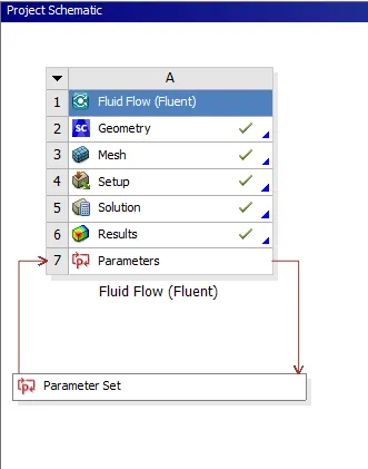
Project schematic:
Geometry:
- Loaded the given gate valve step file into the Spaceclaim.
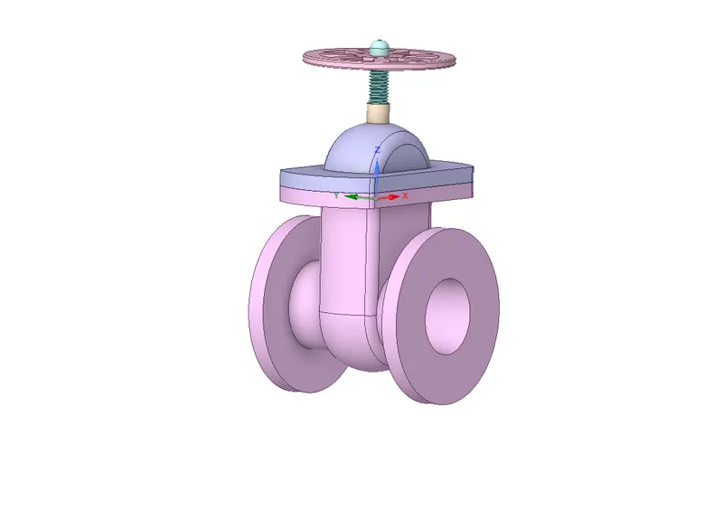
Fig-1: Gate Valve CAD Model
- Then proceeded to hide all components of the gate disc other than the Spindle & Gate Disc
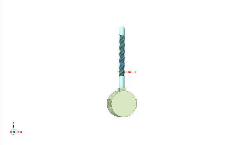
Fig-2: Gate Disc & Spindle
- Went to the "Design" tab and choose the "Move" option and further selected "Move Component" and then selected the Gate Disc. Then Coordinate system appeared on the Gate Disc, then proceeded to move the Gate disc towards the top of the spindle.
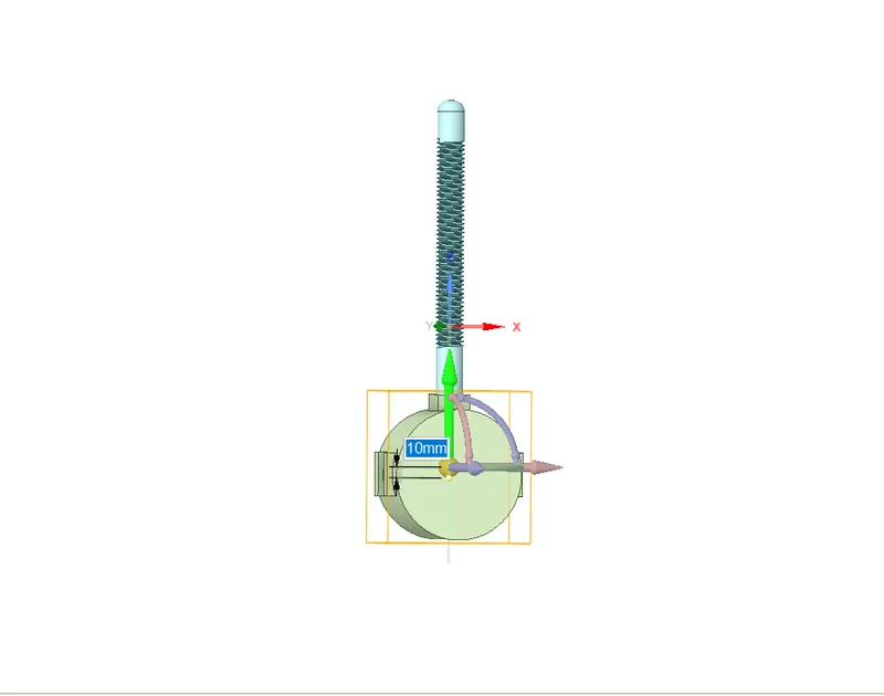
Fig-3: Moving the Gate Disc
- To parametrize went to the Groups menu, In the Group menu, clicked on the Create Parameter button, then there a Group-1 appeared in which we can edit the dimensions of the lift. This will have parametrized the Gate Disc lift.
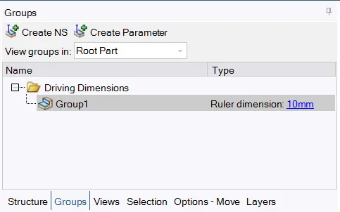
Fig-4: Parametrization
- Then extracted the fluid volume by using the volume extraction option in the prepare tab. Then selected the inlet, outlet and after hiding the bonnet selected the top edge.
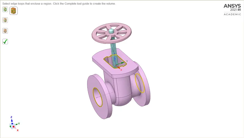
Fig-5: Volume Extraction
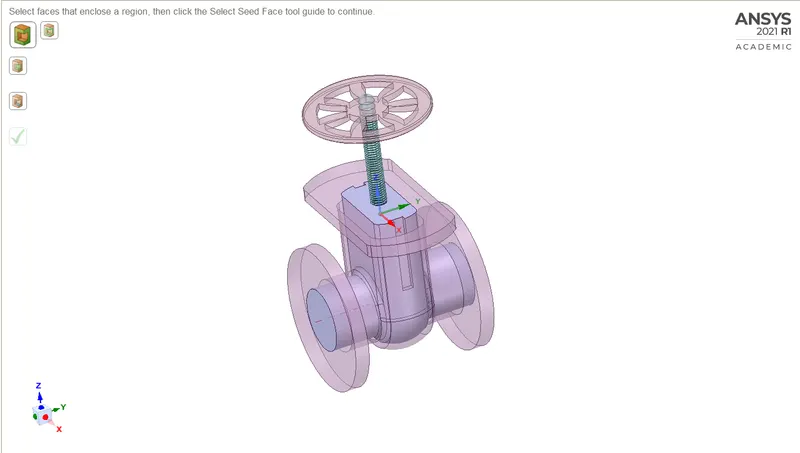 Fig-6: Extracted Volume
- The fluid volume is increased by pulling the pipe's outer solid surface from both sides.
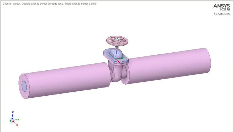
Fig-7: Increased Outer Surface
- Checked out the fluid volume that is created
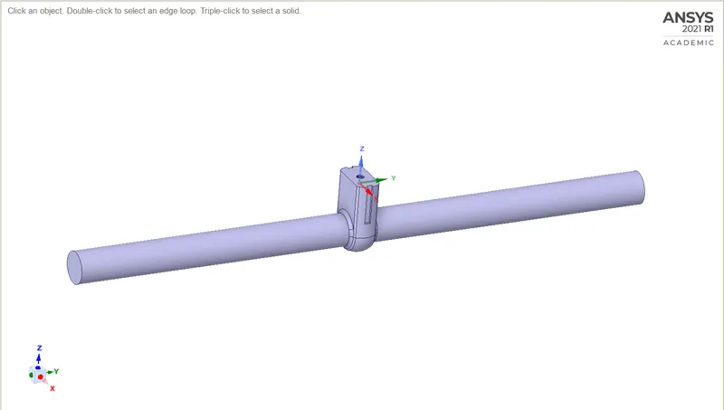
Fig-8: Created Fluid Volume
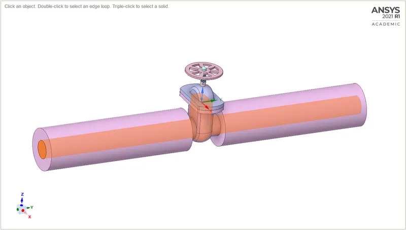
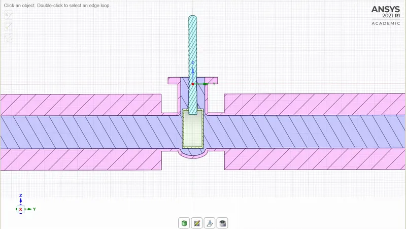
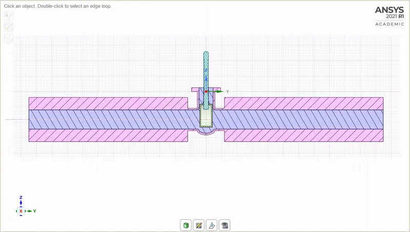
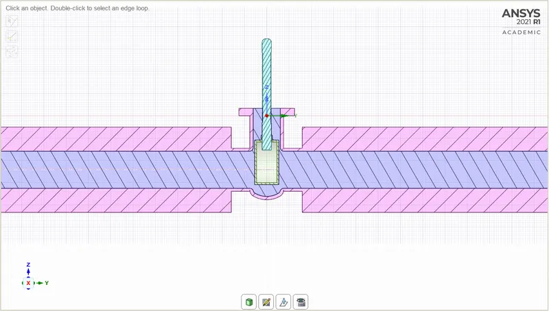
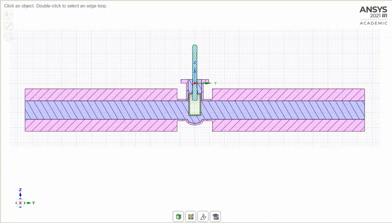
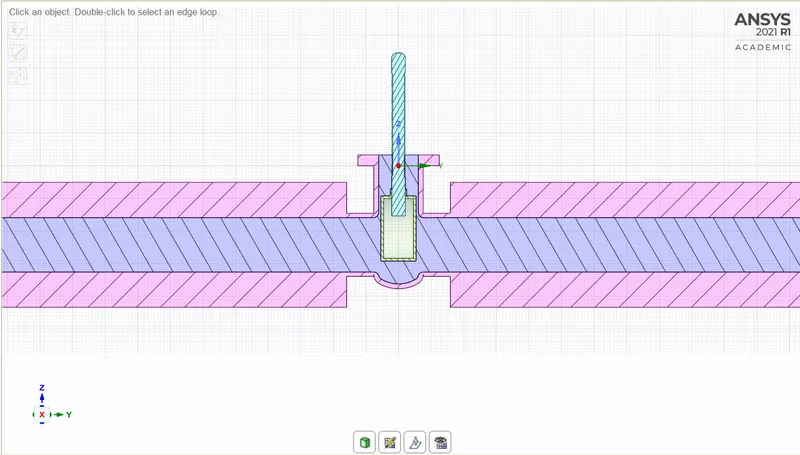
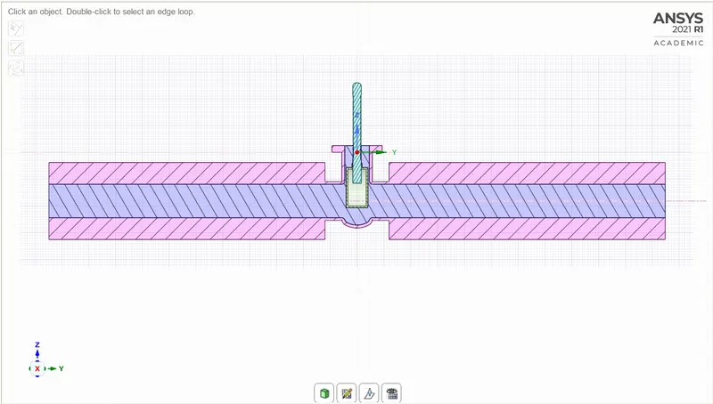
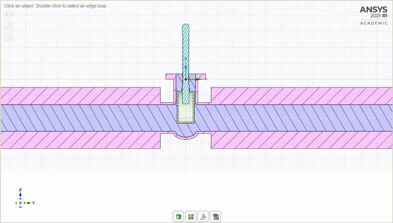
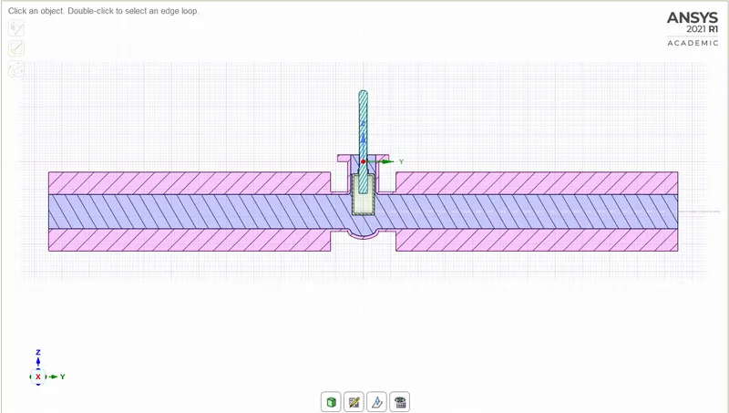
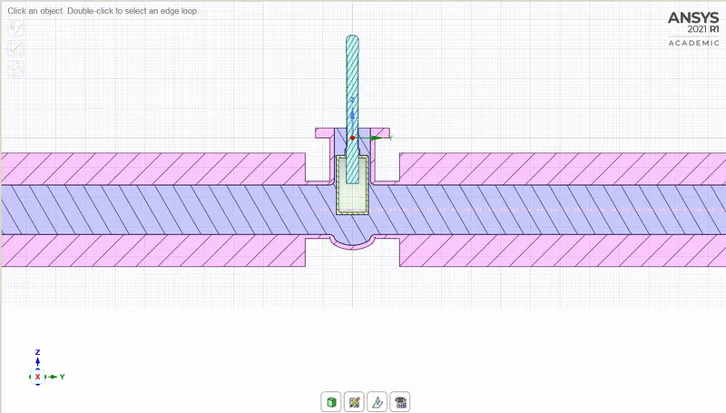
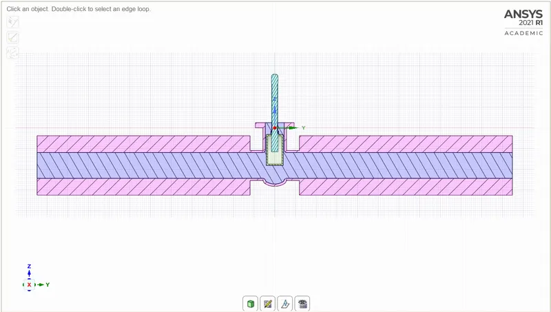
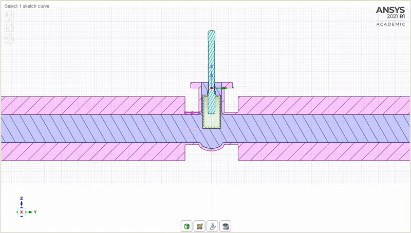
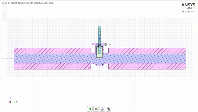
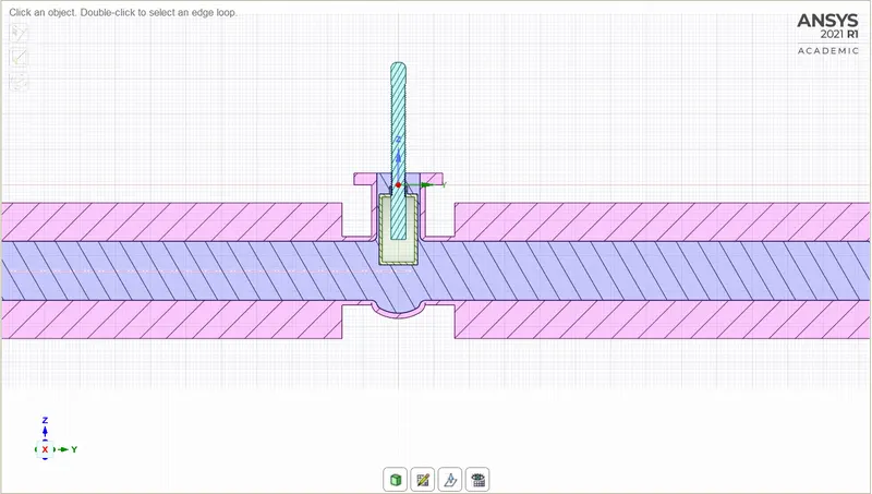
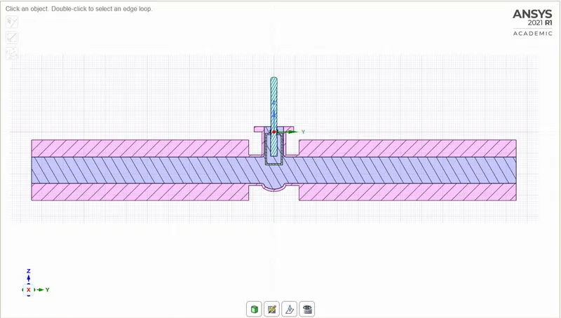
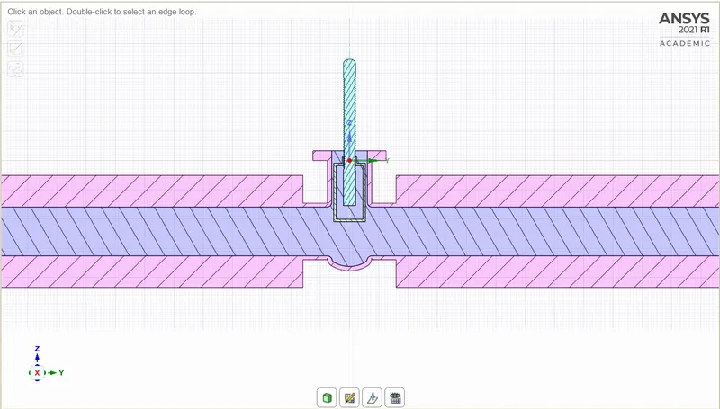
- Went to the section mode and clicked on the YZ-plane to get out the cut-through section, then after zooming in it is observed that the fluid volume had not adapted to the lift in the gate disc. To adapt the fluid volume with the lift, went to the volume, right-clicked on it the went to the update volume body in context option.
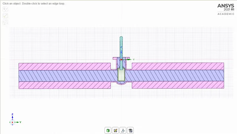
Fig-9: Section Mode of 10mm lift of Gate Disc
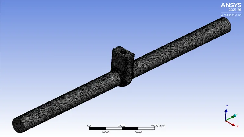
Mesh:
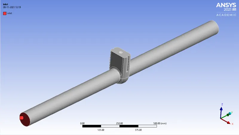
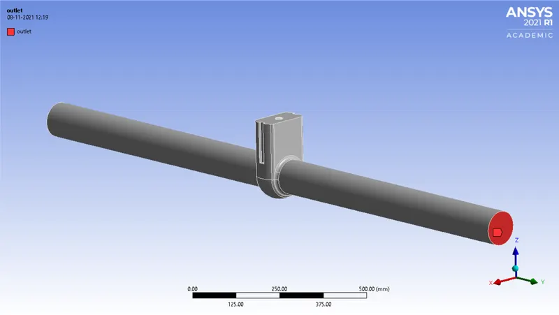
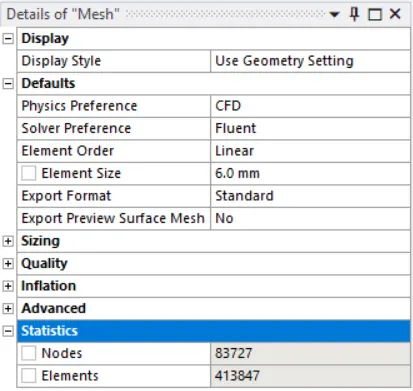
Setup:
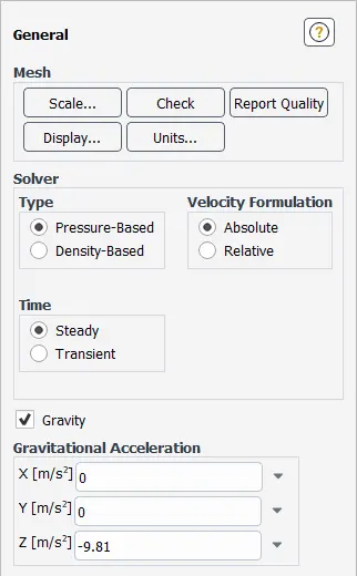
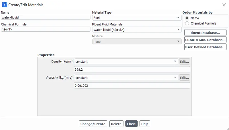
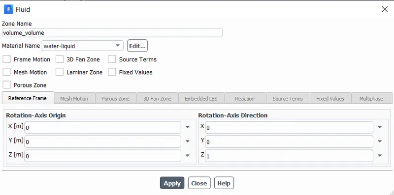
- Here we are choosing the pressure inlet instead of the velocity inlet, to get the velocity of the flow we had to initialize the solution.
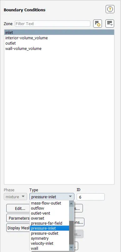
- Typically for pipe flow, Inlet Pressure 10 Pa is acceptable. So that we have taken inlet pressure 10 Pa.
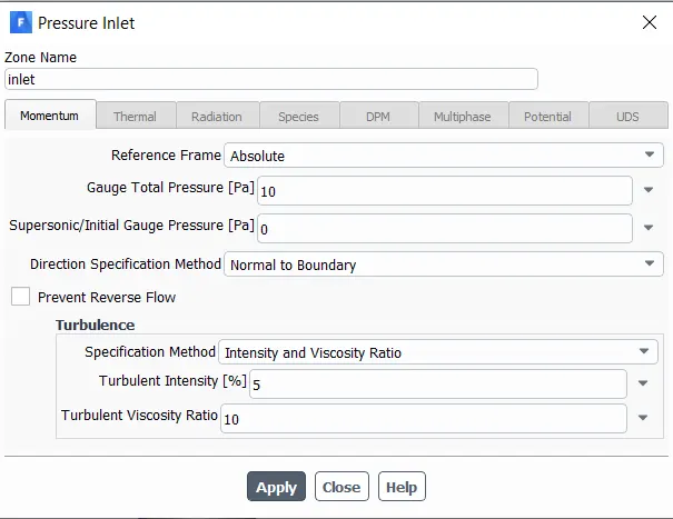
- Went to the solution, and selected Standard Initialization, and initialized from the inlet.
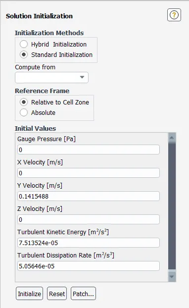
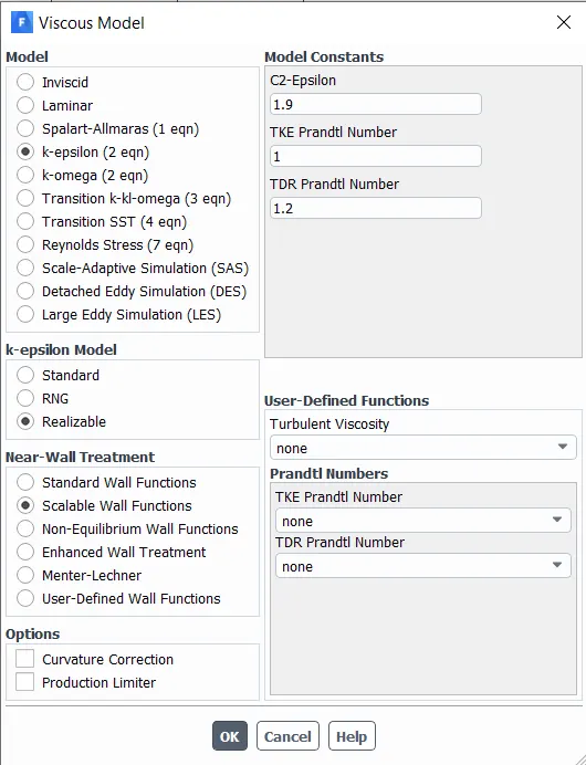
- In the Viscous model, we have taken the K-epsilon model. After initialization, we can get the velocity and calculate the Raynolds number and from that, we decided to choose an appropriate viscous model.
Density, `rho = 998.2 (kg)/m^3`
Velocity, V = `0.1415488 m/s` (from the above image)
Diameter, D = 0.1m (from the SpaceClaim)
Viscosity, `mu = 0.001003 (kg)/(m s)`
Now Reynolds Number, Re = `(rho*V*D)/(mu) = (998.2*0.1415488*0.1)/(0.001003)`
=`14087.1398`
- From the above calculation, we can see the Raynolds number is 14087.14 that is more than 2000. It means the flow is turbulent. which is why we have taken the K-epsilon turbulence model.
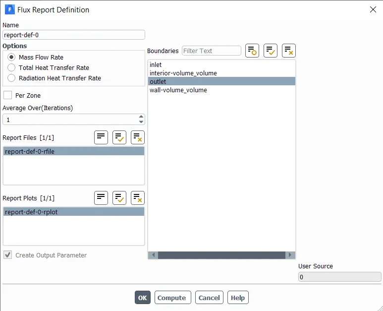
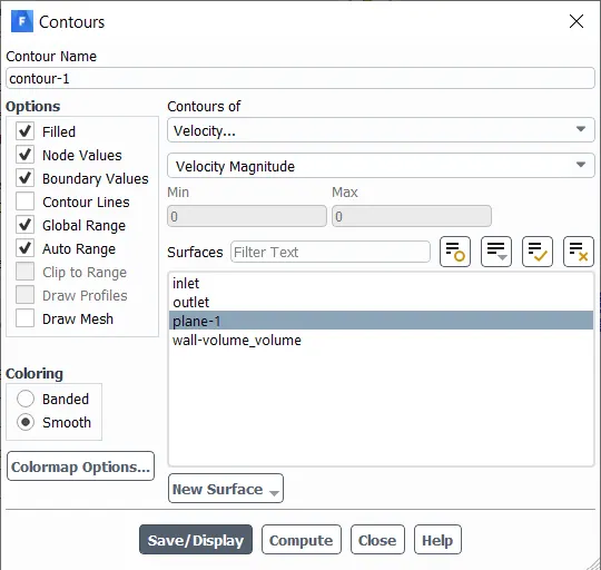
Parametric Result for every Design Points:
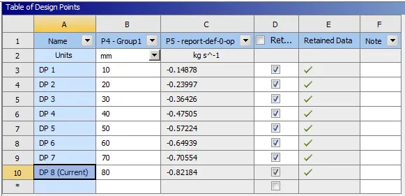
- Here we have given different inputs for all the lift of gate disc as 10 to 80mm and also selected all the checkboxes in retain column for all design points. Then updated all design points.
- After updating all the design points, the Results of the Mass Flow Rate of all the design points were generated automatically as are shown in the table below. These results are calculated based on the lift of the Gate Disc.
Results:
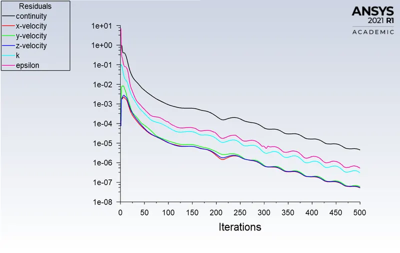
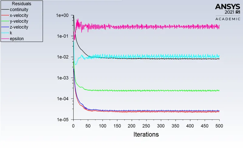
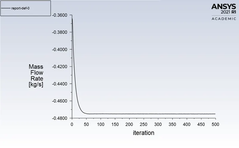
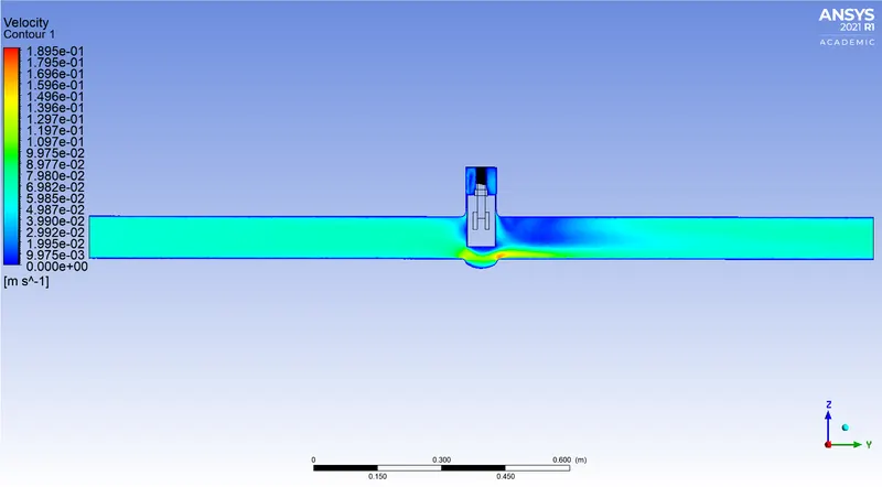
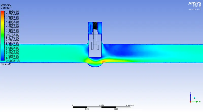
By selecting each Design point and making it the Current design point, we can check all design points one by one and can get Residuals, Mass Flow Rate plot, Velocity, and Pressure Contours, and all required plots.
In the Results section, we will see all the cases of lift of gate disc from 10mm to 80mm one by one. We will calculate the Flow Coefficient and Flow Factor one by one after getting the value of the Mass Flow Rate and outlet pressure from the simulation.
Flow Coefficient:
The flow coefficient of a device is a relative measure of its efficiency at allowing fluid flow. It describes the relationship between the pressure drop across an orifice valve or other assembly and the corresponding flow rate.
Mathematically the flow coefficient Cv (or flow-capacity rating of the valve) can be expressed as:
`C_v = Qsqrt((SG)/(DeltaP))`
where:
Q is the rate of flow (expressed in US gallons per minute).
SG is the specific gravity of the fluid (for water = 1)
`DeltaP` is the pressure drop across the valve.
In more practical terms, the flow coefficient `C_v` is the volume (in US gallons) of water at `60^oF` that will flow per minute through a valve with a pressure drop of 1 psi across the valve.
The use of the flow coefficient offers a standard method of comparing valve capacities and sizing valves for specific applications that are widely accepted by the industry. The general definition of the flow coefficient can be expanded into equations modeling the flow of liquids, gases, and steam using the discharge coefficient.
Flow Factor:
The metric equivalent flow factor (Kv; commonly used everywhere else in the world with the exception of the United States) is calculated using metric units:
`K_v = Qsqrt((SG)/(DeltaP))`
Where;
`K_v` is the flow factor (expressed in `[m^3*h^-1]`).
Q is the flow rate (expressed in cubic meters per hour [`m^3/h`]).
SG is the specific gravity of the fluid (for water = 1).
`DeltaP` is the differential pressure across the device (expressed in [bar]).
`K_v` can be calculated from `C_v` using the equation:
`K_v = 0.865*C_v`
Case-1 10mm lift:
Residuals
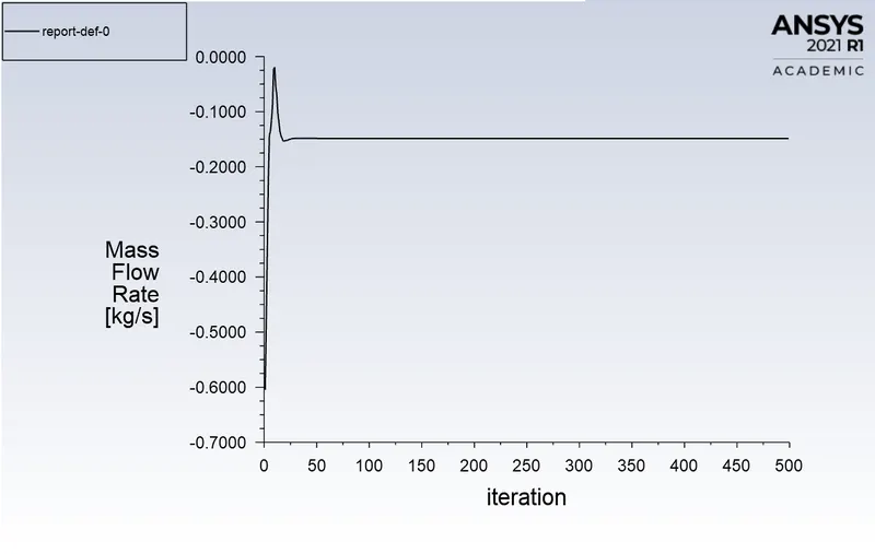
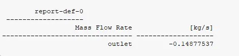
Mass Flow Rate
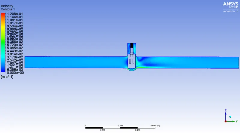
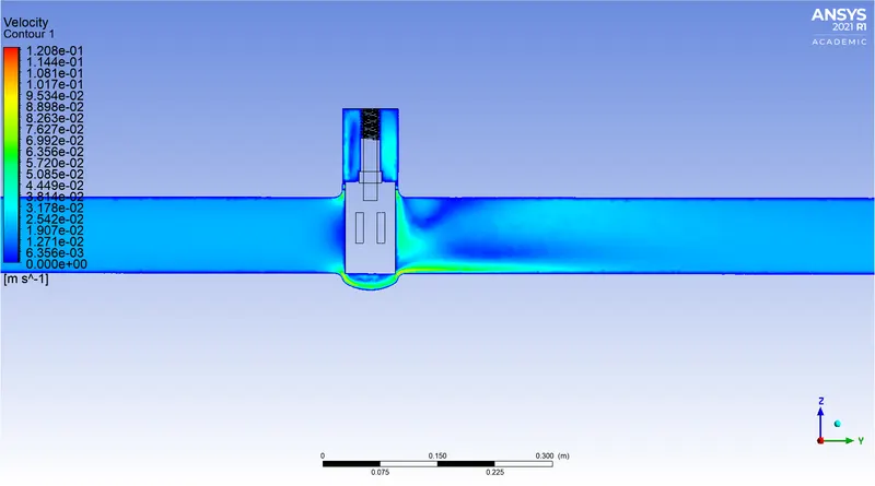
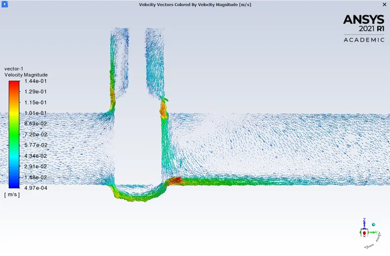
Velocity Contours
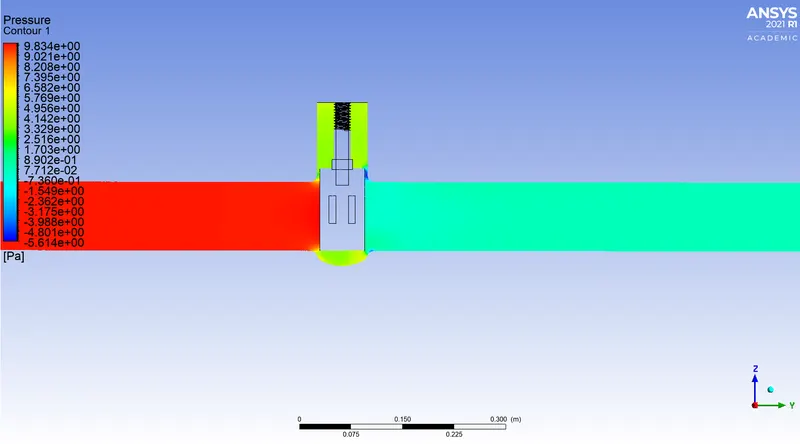
Pressure Contour

Calculation of Flow Coefficient and Flow Factor when 10mm lift of gate disc:
Mass Flow Rate = 0.14877537 `(kg)/s`
Flow Rate, Q = `3.6*0.14877537``m^3/h` [`1(kg)/s = 3.6 m^3/h`]
Q = 0.5356 `m^3/h`
Specific Gravity, SG = 1
Inlet Pressure = 10 Pa
Outlet Pressure = 0.18298261 Pa
Pressure Difference, `Delta P` = Inlet Pressure - Outlet Pressure =10 Pa - 0.18298261 Pa = 9.8170 Pa = `9.8170*10^-5`bar = `9.8170e-05`bar
Now the Flow Factor, `K_v = Q sqrt((SG)/(DeltaP))` `m^3/h`
`K_v= 0.5356*sqrt((1)/(9.8170e-05)`
`K_v = 54.056` `m^3/h`
Now the Flow Coefficient, `C_v= K_v /0.865`
`C_v = 54.056/0.865`
`C_v = 62.492`
Case-2 20mm lift:
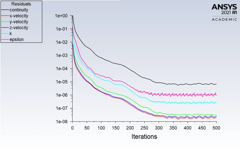
Residuals
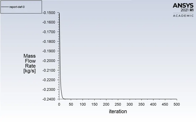
Mass Flow Rate

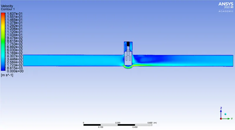
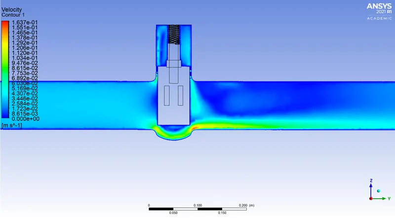
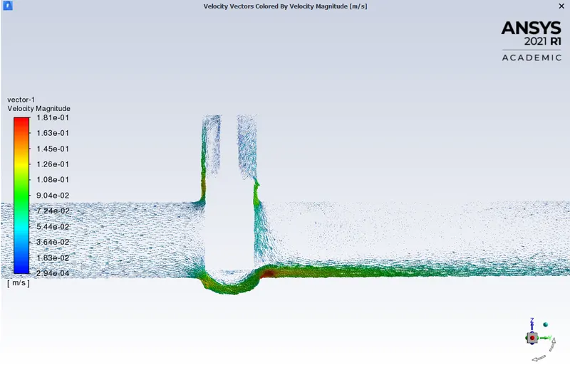
Velocity Contours
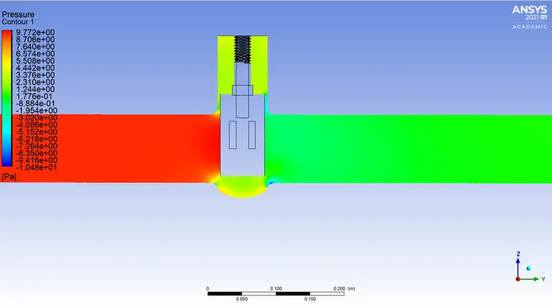
Pressure contour

Calculation of Flow Coefficient and Flow Factor when 20mm lift of gate disc:
Mass Flow Rate = 0.23996629 `(kg)/s`
Flow Rate, Q = `3.6*0.23996629``m^3/h` [`1(kg)/s = 3.6 m^3/h`]
Q = 0.8639 `m^3/h`
Specific Gravity, SG = 1
Inlet Pressure = 10 Pa
Outlet Pressure = 0.4747349 Pa
Pressure Difference, `Delta P` = Inlet Pressure - Outlet Pressure =10 Pa - 0.4747349 Pa = 9.5253 Pa = `9.5253*10^-5`bar = `9.5253e-05`bar
Now the Flow Factor, `K_v = Q sqrt((SG)/(DeltaP))` `m^3/h`
`K_v= 0.8639*sqrt((1)/(9.5253e-05)`
`K_v = 88.514` `m^3/h`
Now the Flow Coefficient, `C_v= K_v /0.865`
`C_v = 88.514/0.865`
`C_v = 102.33`
Case-3 30mm lift:
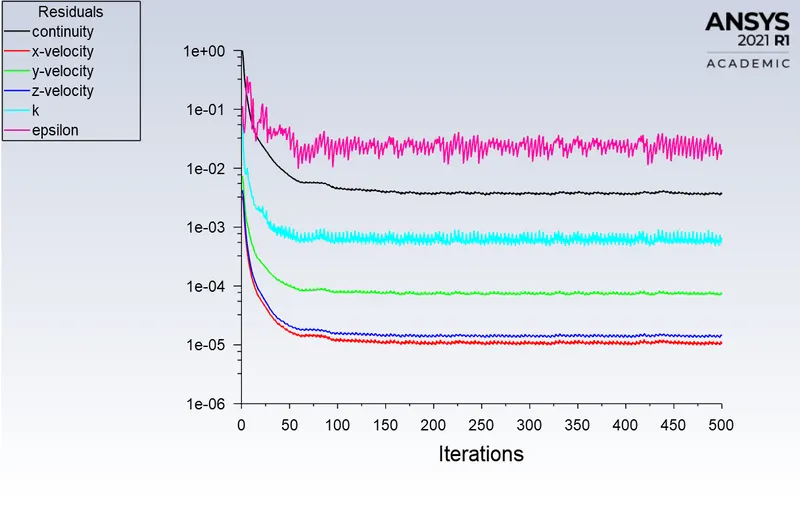
Residuals
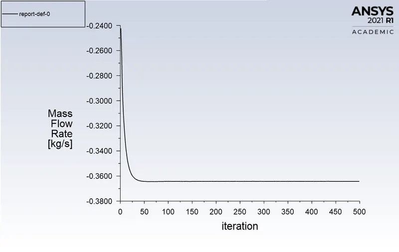
Mass Flow Rate

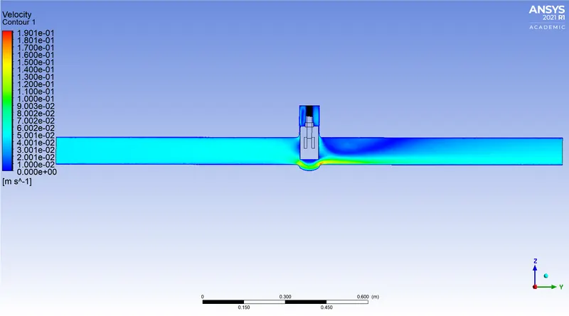
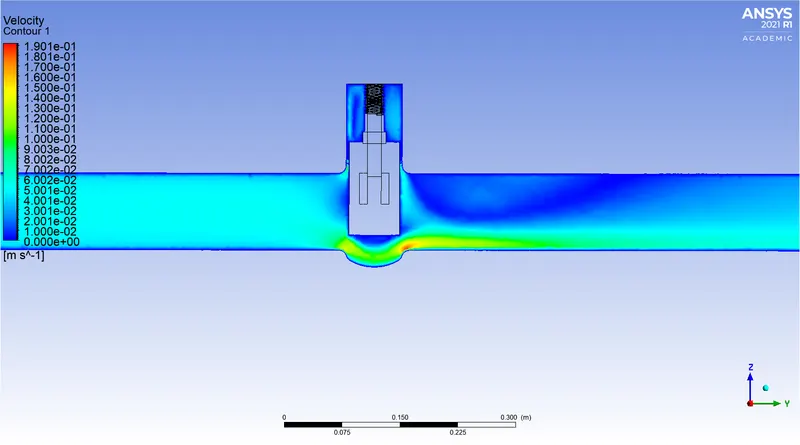
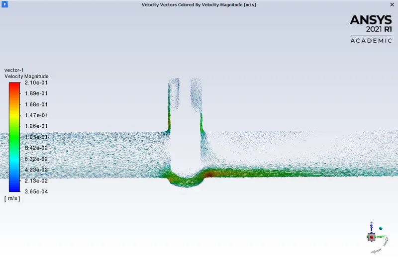
Velocity Contours
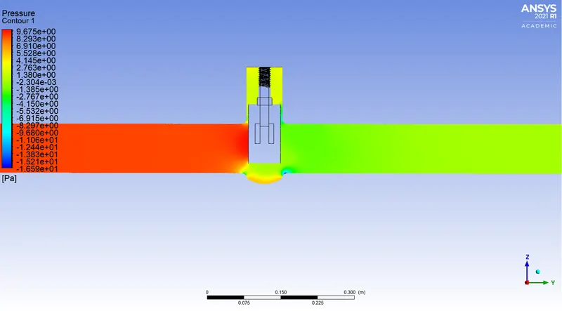
Pressure Contour

Calculation of Flow Coefficient and Flow Factor when 30mm lift of gate disc:
Mass Flow Rate = 0.36425741 `(kg)/s`
Flow Rate, Q = `3.6*0.36425741``m^3/h` [`1(kg)/s = 3.6 m^3/h`]
Q = 1.3113 `m^3/h`
Specific Gravity, SG = 1
Inlet Pressure = 10 Pa
Outlet Pressure = 1.0955081 Pa
Pressure Difference, `Delta P` = Inlet Pressure - Outlet Pressure =10 Pa - 1.0955081 Pa = 8.9045 Pa = `8.9045*10^-5`bar = `8.9045e-05`bar
Now the Flow Factor, `K_v = Q sqrt((SG)/(DeltaP))` `m^3/h`
`K_v= 1.3113*sqrt((1)/(8.9045e-05)`
`K_v = 138.97` `m^3/h`
Now the Flow Coefficient, `C_v= K_v /0.865`
`C_v = 138.97/0.865`
`C_v = 160.65`
Case-4 40mm lift:
Residuals
Mass Flow Rate

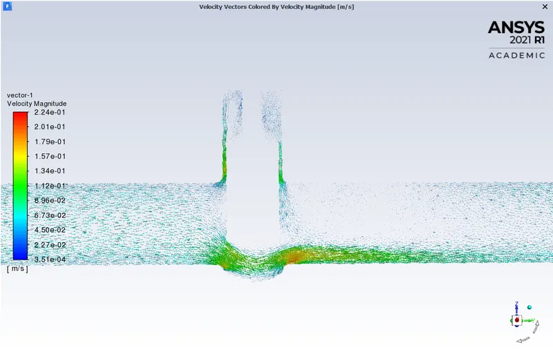
Velocity Contour
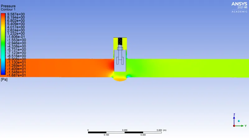
Pressure Contour

Calculation of Flow Coefficient and Flow Factor when 40mm lift of gate disc:
Mass Flow Rate = 0.47505349 `(kg)/s`
Flow Rate, Q = `3.6*0.47505349``m^3/h` [`1(kg)/s = 3.6 m^3/h`]
Q = 1.7102 `m^3/h`
Specific Gravity, SG = 1
Inlet Pressure = 10 Pa
Outlet Pressure = 1.8635001 Pa
Pressure Difference, `Delta P` = Inlet Pressure - Outlet Pressure =10 Pa - 1.8635001 Pa = 8.1365 Pa = `8.1365*10^-5`bar = `8.1365e-05`bar
Now the Flow Factor, `K_v = Q sqrt((SG)/(DeltaP))` `m^3/h`
`K_v= 1.7102*sqrt((1)/(8.1365e-05)`
`K_v = 189.59` `m^3/h`
Now the Flow Coefficient, `C_v= K_v /0.865`
`C_v = 189.59/0.865`
`C_v = 219.18`
Case-5 50mm lift:
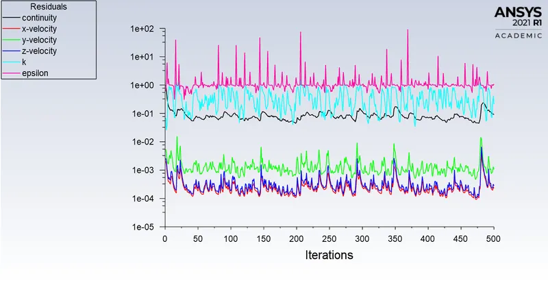
Residuals
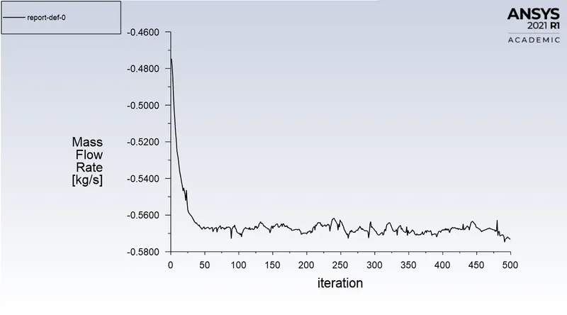
Mass Flow Rate

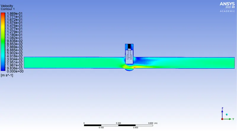
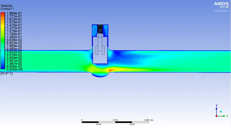
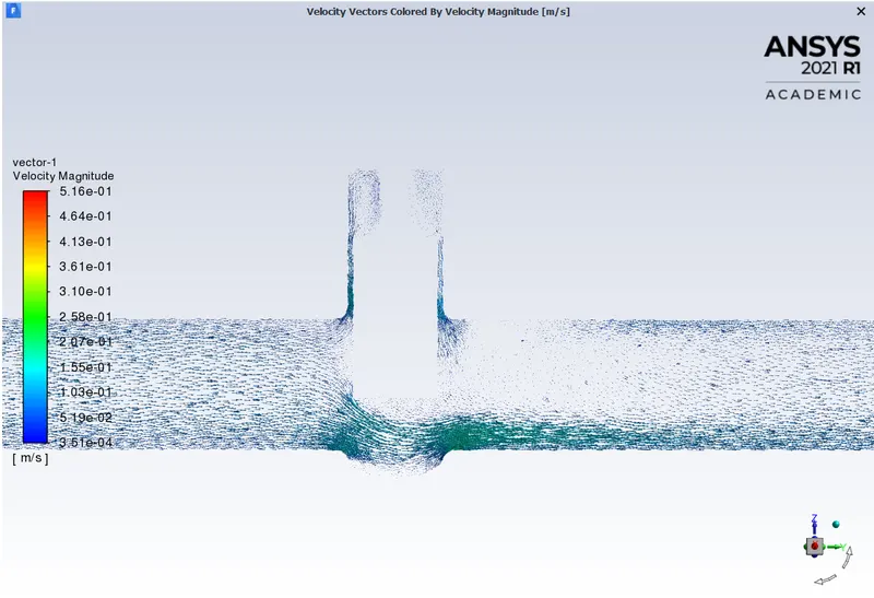
Velocity Contours
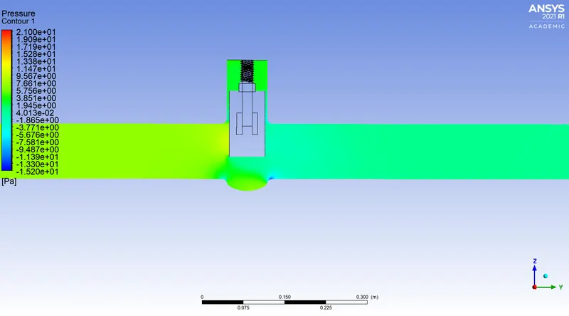
Pressure Contour

Calculation of Flow Coefficient and Flow Factor when 50mm lift of gate disc:
Mass Flow Rate = 0.57223597 `(kg)/s`
Flow Rate, Q = `3.6*0.57223597``m^3/h` [`1(kg)/s = 3.6 m^3/h`]
Q = 2.0600 `m^3/h`
Specific Gravity, SG = 1
Inlet Pressure = 10 Pa
Outlet Pressure = 2.7138667 Pa
Pressure Difference, `Delta P` = Inlet Pressure - Outlet Pressure =10 Pa - 2.7138667 Pa = 7.2861 Pa = `7.2861*10^-5`bar = `7.2861e-05`bar
Now the Flow Factor, `K_v = Q sqrt((SG)/(DeltaP))` `m^3/h`
`K_v= 2.0600*sqrt((1)/( 7.2861e-05)`
`K_v = 241.34` `m^3/h`
Now the Flow Coefficient, `C_v= K_v /0.865`
`C_v = 241.34/0.865`
`C_v = 279.01`
Case-6 60mm lift:
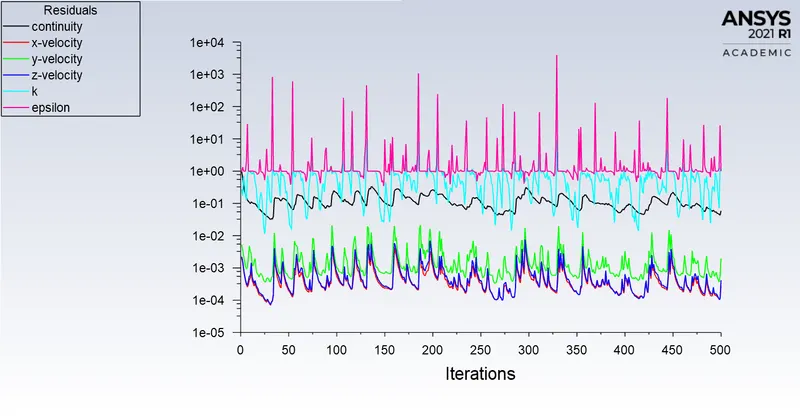
Residuals
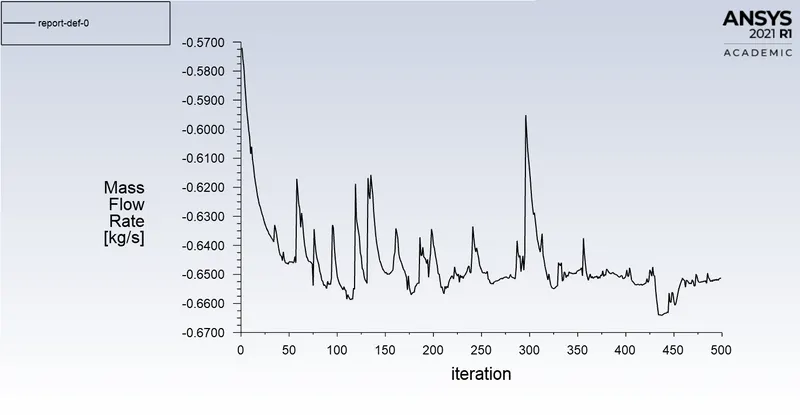
Mass Flow Rate

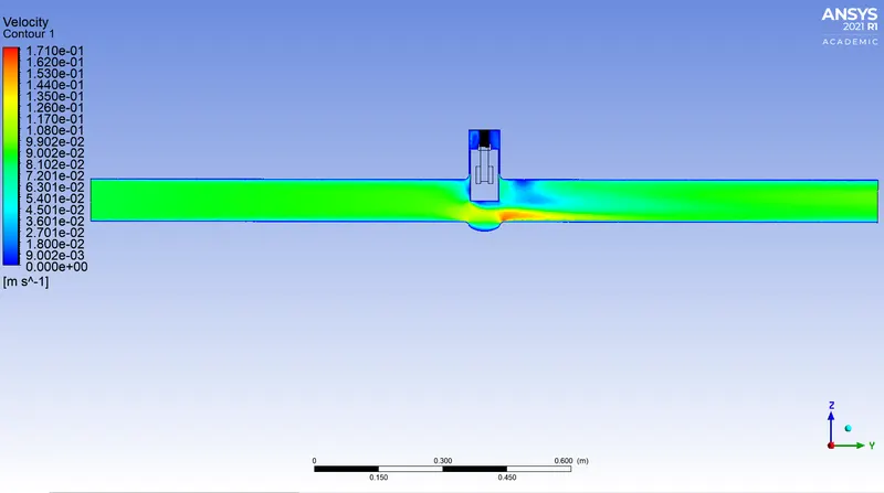
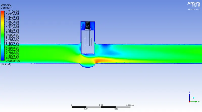
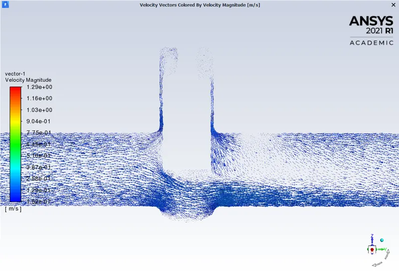
Velocity Contours
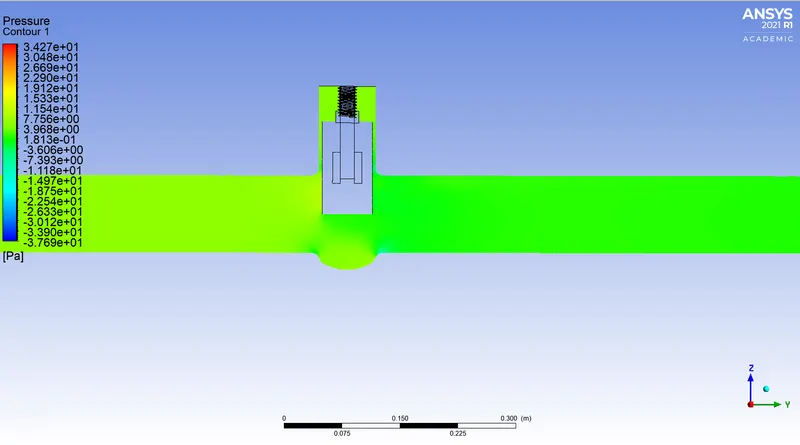
Pressure Contour

Calculation of Flow Coefficient and Flow Factor when 60mm lift of gate disc:
Mass Flow Rate = 0.64939312 `(kg)/s`
Flow Rate, Q = `3.6*0.64939312``m^3/h` [`1(kg)/s = 3.6 m^3/h`]
Q = 2.3378 `m^3/h`
Specific Gravity, SG = 1
Inlet Pressure = 10 Pa
Outlet Pressure = 3.5148224 Pa
Pressure Difference, `Delta P` = Inlet Pressure - Outlet Pressure =10 Pa - 3.5148224 Pa = 6.4852 Pa = `6.4852*10^-5`bar = ` 6.4852e-05`bar
Now the Flow Factor, `K_v = Q sqrt((SG)/(DeltaP))` `m^3/h`
`K_v= 2.3378*sqrt((1)/( 6.4852e-05)`
`K_v = 290.30` `m^3/h`
Now the Flow Coefficient, `C_v= K_v /0.865`
`C_v = 290.30/0.865`
`C_v = 335.61`
Case-7 70mm lift:
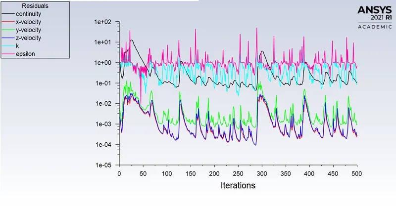
Residuals
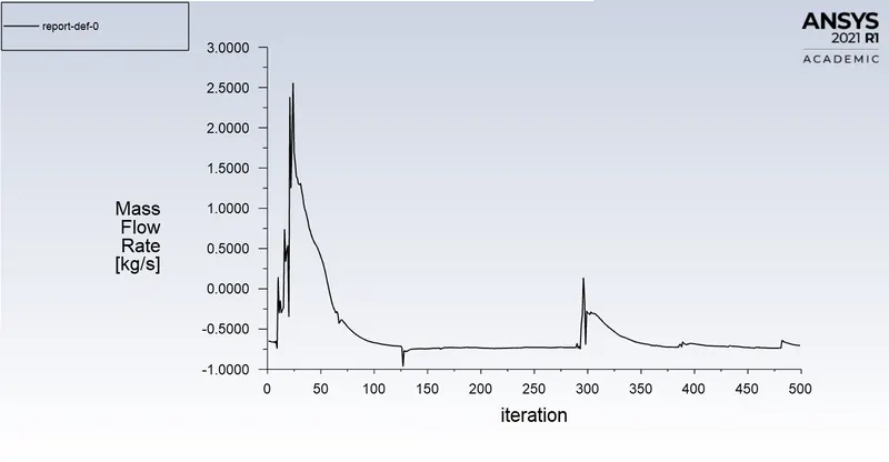
Mass Flow Rate

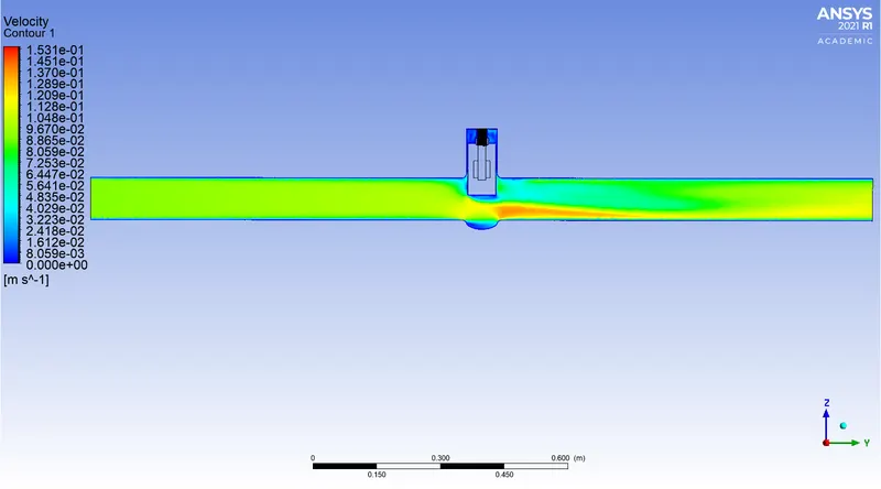
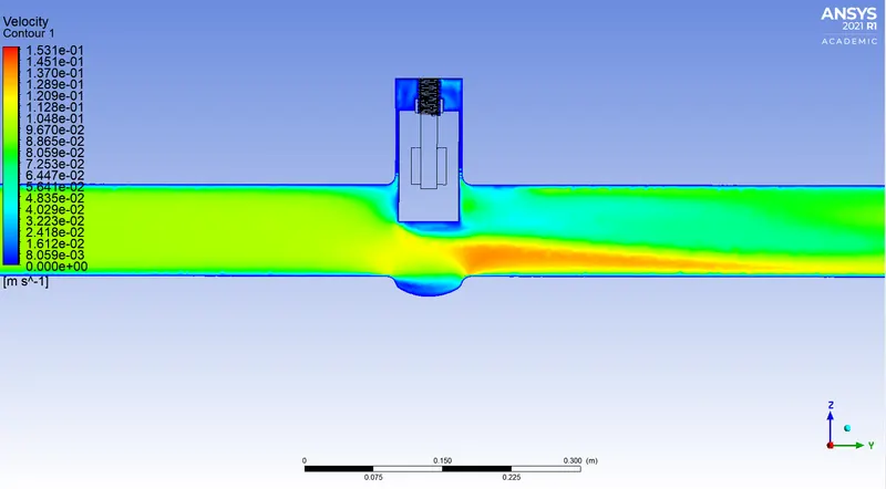
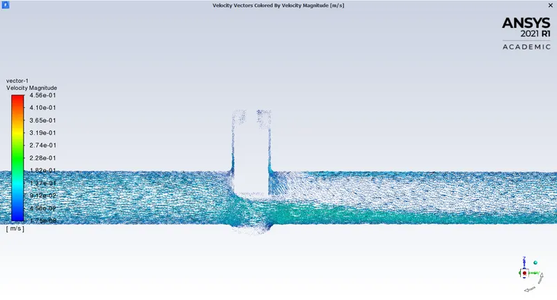
Velocity Contours
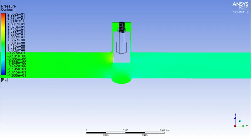
Pressure Contour

Calculation of Flow Coefficient and Flow Factor when 70mm lift of gate disc:
Mass Flow Rate = 0.70553604 `(kg)/s`
Flow Rate, Q = `3.6*0.70553604``m^3/h` [`1(kg)/s = 3.6 m^3/h`]
Q = 2.5399 `m^3/h`
Specific Gravity, SG = 1
Inlet Pressure = 10 Pa
Outlet Pressure = 4.1858412 Pa
Pressure Difference, `Delta P` = Inlet Pressure - Outlet Pressure =10 Pa - 4.1858412 Pa = 5.8142 Pa = `5.8142*10^-5`bar = ` 5.8142e-05`bar
Now the Flow Factor, `K_v = Q sqrt((SG)/(DeltaP))` `m^3/h`
`K_v= 2.5399*sqrt((1)/(5.8142e-05)`
`K_v = 333.10` `m^3/h`
Now the Flow Coefficient, `C_v= K_v /0.865`
`C_v = 333.10/0.865`
`C_v = 385.09`
Case-8 80mm lift:
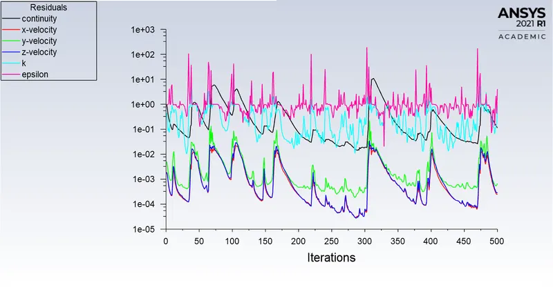
Residuals
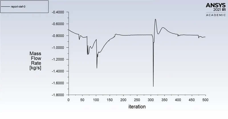
Mass Flow Rate

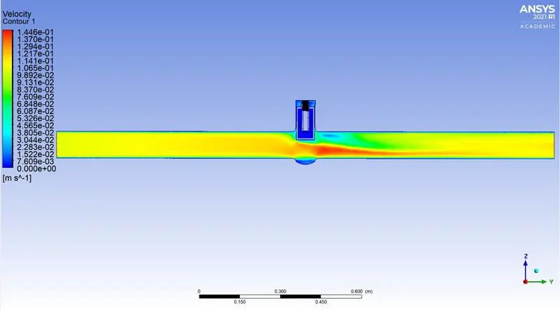
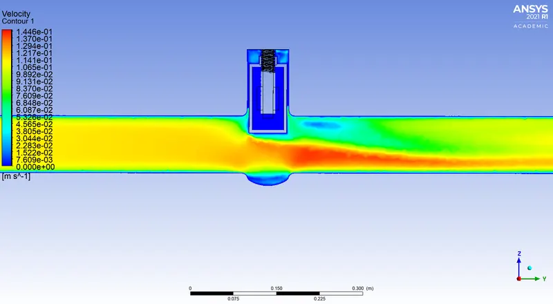
Velocity Contours
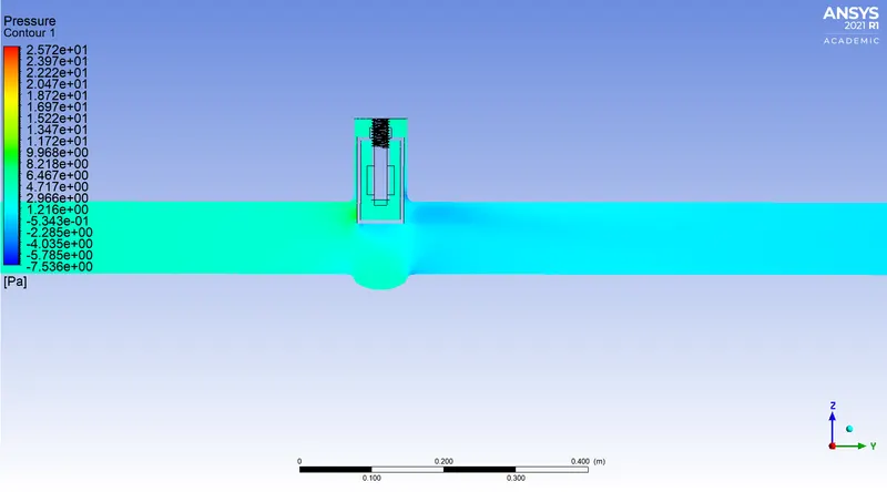
Pressure Contour

Calculation of Flow Coefficient and Flow Factor when 80mm lift of gate disc:
Mass Flow Rate = 0.82183609 `(kg)/s`
Flow Rate, Q = `3.6*0.82183609``m^3/h` [`1(kg)/s = 3.6 m^3/h`]
Q = 2.9586 `m^3/h`
Specific Gravity, SG = 1
Inlet Pressure = 10 Pa
Outlet Pressure = 5.5776342 Pa
Pressure Difference, `Delta P` = Inlet Pressure - Outlet Pressure =10 Pa - 5.5776342 Pa = 4.4224 Pa = `4.4224*10^-5`bar = `4.4224e-05`bar
Now the Flow Factor, `K_v = Q sqrt((SG)/(DeltaP))` `m^3/h`
`K_v= 2.9586*sqrt((1)/(4.4224e-05)`
`K_v = 444.90` `m^3/h`
Now the Flow Coefficient, `C_v= K_v /0.865`
`C_v = 444.90/0.865`
`C_v = 514.33`
Observations from Velocity and Pressure Contours:
From the Velocity Contours, it is observed that, as the lift of the gate disc increases, the velocity of the flow increases. as we can see in the starting case that the velocity is very low and as the lift of the gate disc increases the velocity increases.
From the Pressure Contours, it is observed that the pressure on the inlet side of the valve is high, and as the flow passes through the opening, pressure decreases. It is also noticed in the first case, the pressure on the inlet side is very high in comparison to another side of the valve, so we can say that the low lift height refers to the higher pressure drop and low flow rate through the valve.
Observations from above Calculations:
|
Lift of Gate Disc (mm) |
Inlet Pressure (Pa) |
Outlet Pressure (Pa) |
Pressure Difference (Pa) |
Mass Flow Rate (kg/s) | Flow Factor`(K_v)` `(m^3/h)` | Flow Coefficient `C_v` |
| 10 | 10 | 0.18298261 | 9.8170 | 0.14878 | 54.056 | 62.492 |
| 20 | 10 | 0.47473749 | 9.5253 | 0.23997 | 88.514 | 102.33 |
| 30 | 10 | 1.0955081 | 8.9045 | 0.36426 | 138.97 | 160.65 |
| 40 | 10 | 1.8635001 | 8.1365 | 0.47505 | 189.59 | 219.18 |
| 50 | 10 | 2.7138667 | 7.2861 | 0.57224 | 241.34 | 279.01 |
| 60 | 10 | 3.5148224 | 6.4852 | 0.64939 | 290.30 | 335.61 |
| 70 | 10 | 4.1858412 | 5.8142 | 0.70554 | 333.10 | 385.09 |
| 80 | 10 | 5.5776342 | 4.4224 | 0.82184 | 444.90 | 514.33 |
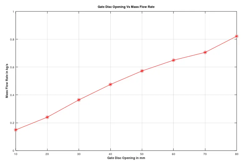
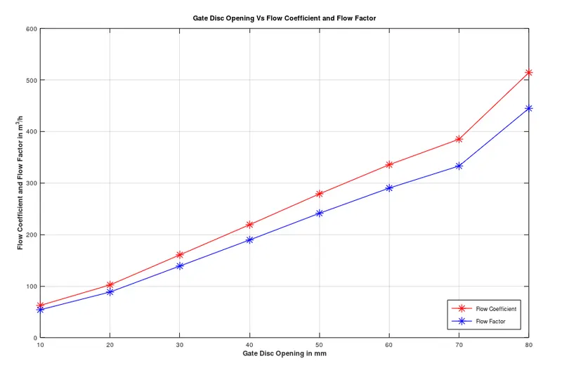
From the above table, it is clearly observed that as the lift of the Gate disc increases, Mass Flow Rate, Flow Coefficient, and Flow Factor increases. All three quantities are gradually increasing as the lift of the gate disc increases and it becomes maximum when the gate disc is fully open.
Graphs:
Gate Disc Opening Vs Mass Flow Rate:
Gate Disc Opening Vs Flow Coefficient and Flow Factor:
CONCLUSION:
- The Flow Coefficient and Flow Factor increase as the Mass Flow Rate through the valve increases.
- Mass Flow Rate increases as the lift of the gate disc increases.
- The low lift height refers to the higher pressure drop and thus low flow rate through the valve.
- Pressure difference decreases with an increase in the lift of the gate disc.