Parametric study on Gate valve.
Parametric study on Gate valve.
INTRODUCTION
A gate valve, also known as a sluice valve, is a valve that opens by lifting a barrier (gate) out of the path of the fluid. Gate valves require very little space along the pipe axis and hardly restrict the flow of fluid when the gate is fully opened.
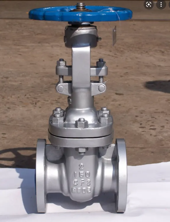
Use of the GATE VALVE
Gate valves are used to shut off the flow of liquids rather than for flow regulation. When fully open, the typical gate valve has no obstruction in the flow path, resulting in very low flow resistance. The size of the open flow path generally varies in a nonlinear manner as the gate is moved. This means that the flow rate does not change evenly with stem travel. Depending on the construction, a partially open gate can vibrate from the fluid flow.
Gate valves are mostly used with larger pipe diameters (from 2" to the largest pipelines) since they are less complex to construct than other types of valves in large sizes.
At high pressures, friction can become a problem. As the gate is pushed against its guiding rail by the pressure of the medium, it becomes harder to operate the valve. Large gate valves are sometimes fitted with a bypass controlled by a smaller valve to be able to reduce the pressure before operating the gate valve itself.
Gate valves without an extra sealing ring on the gate or the seat are used in applications where minor leaking of the valve is not an issue, such as heating circuits or sewer pipes.
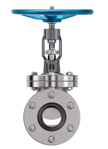
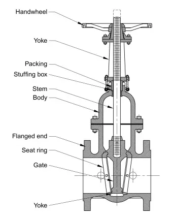
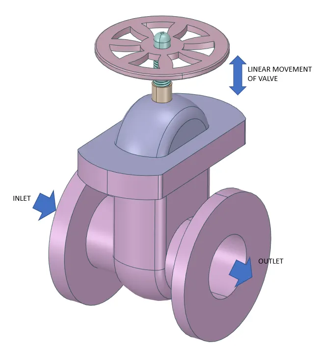
GEOMETRY:-
Import the model
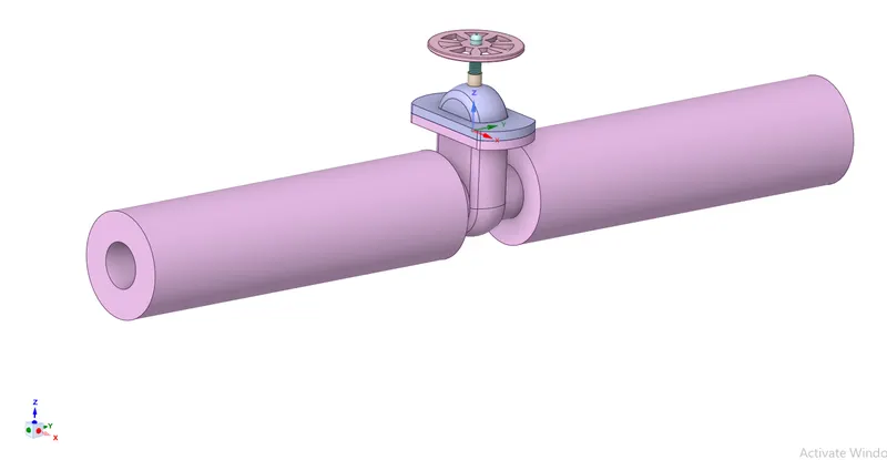
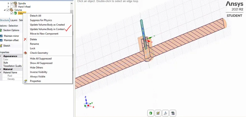
Prepare`->` extract the fluid volume by selecting the edges as shown
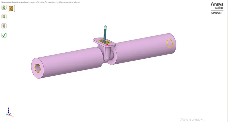
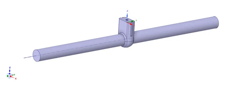
Fluid volume
These are the following steps to create the parameter
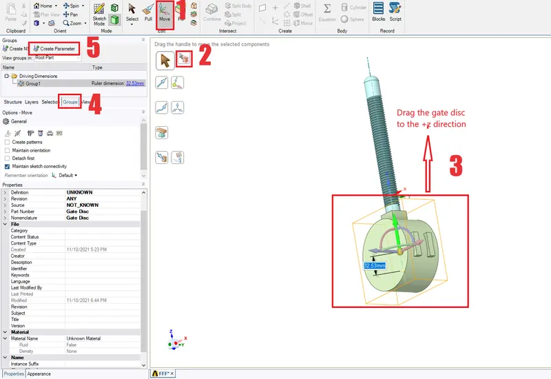
After setting parameter, we have to update the fluid volume
MESHING:-
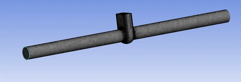
Mesh
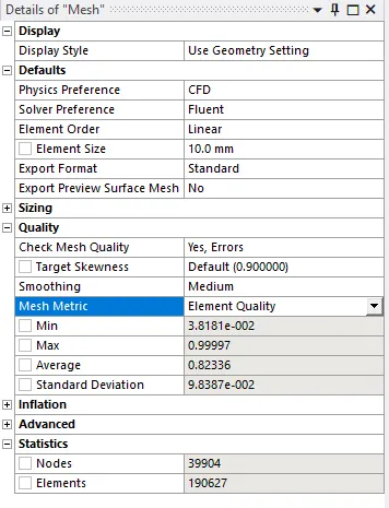
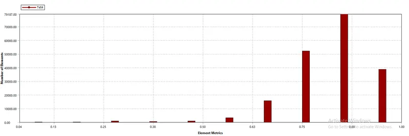
Mesh metrics
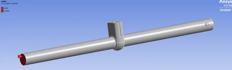
Named selection
SETUP:-
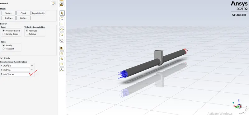
General `->` Gravity z=-9.81 because as we see below bonnet is in the +z direction
Physics`->` models `->` viscous`->`k-epsilon, realizable, scalable wall function
`->` materials `->` copy the water liquid and delete the air after changing in the cell zones volume
`->`zones `->` boundaries `->` inlet `->` pressure inlet as 10 [pa]
Solution`->` report definitions `->` flux reports `->` mass flow rate at outlet
Standard initialization from the inlet
run the simulation for 250 iterations
PARAMETRIC SETUP:-
To perform a parametric study on the gate valve simulation by setting the opening from 10 % to 80%
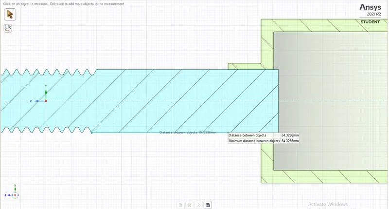
The length of the spindle is 54.32 mm in that we are going to calculate for 10 % to 80% lift of the gate disc
After one simulation click on the parameters and you will see the parameter tab
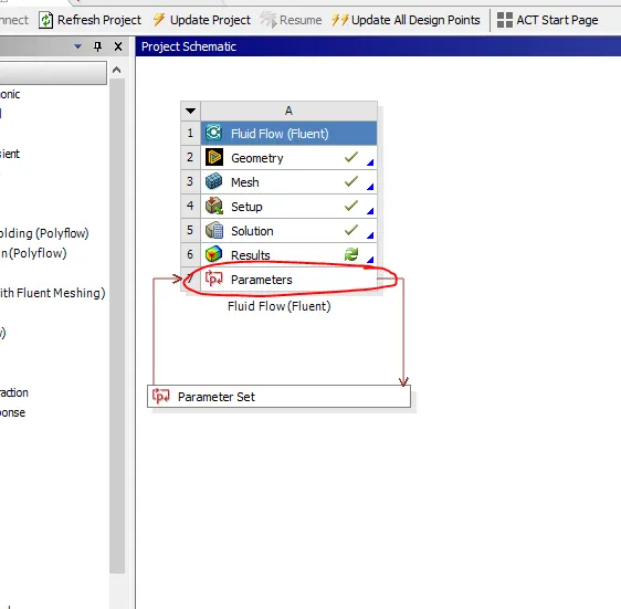
In the parameter tab, we have to enter the lengths of different percentages and click on the update all design points after solving all design points we will get the values
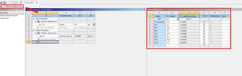
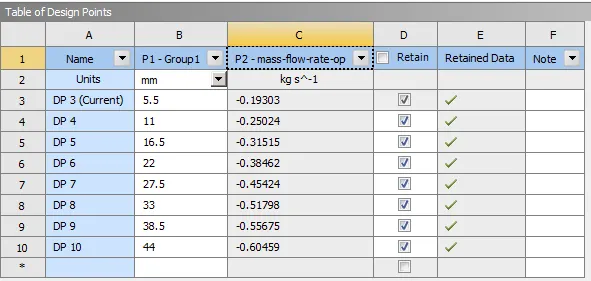
Mass flow rate at the outlet for given lengths
RESULTS:-
To view, the results make DP as the current whichever u want and open results
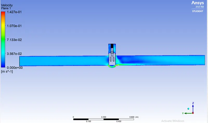
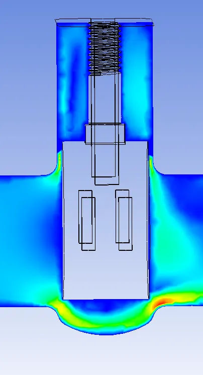
For 10% (5.5 mm) lift of the gate disc
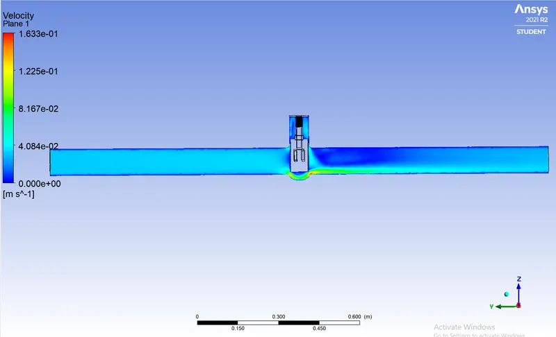
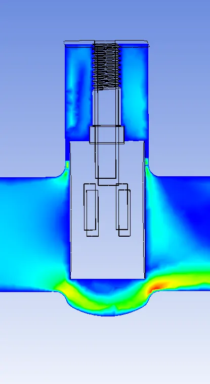
For 20% (11 mm)lift of the gate disc
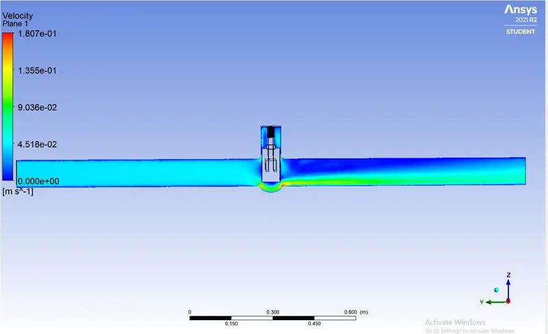
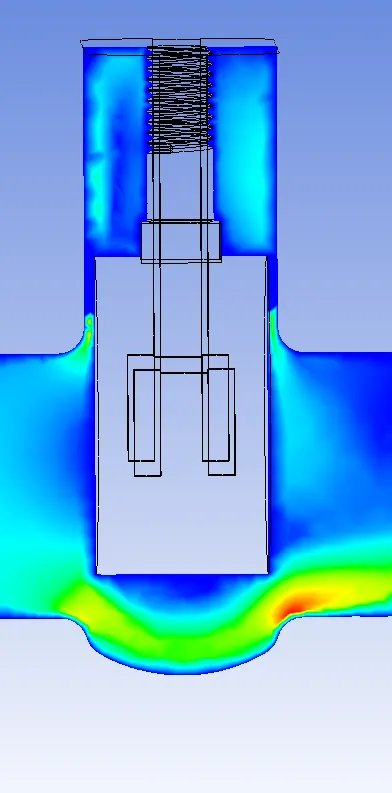
For 30% (16.5 mm) lift of the gate disc
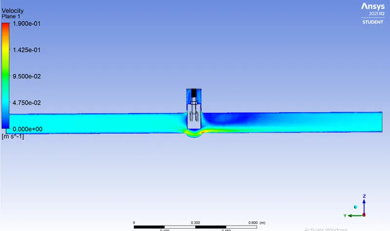
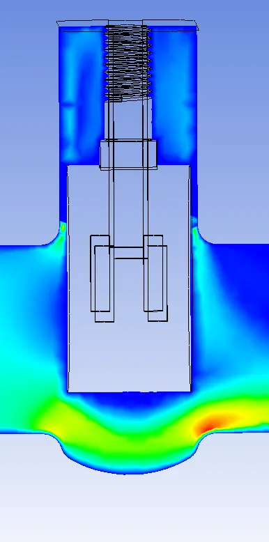
For 40% (22 mm) lift of the gate disc
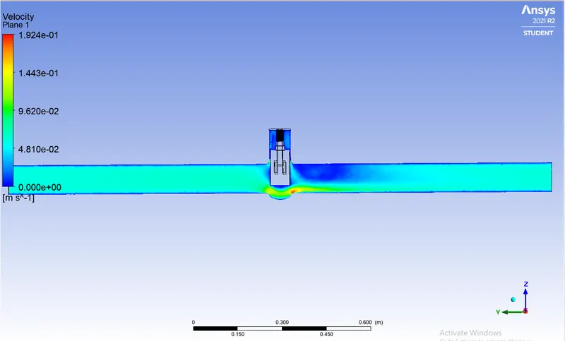
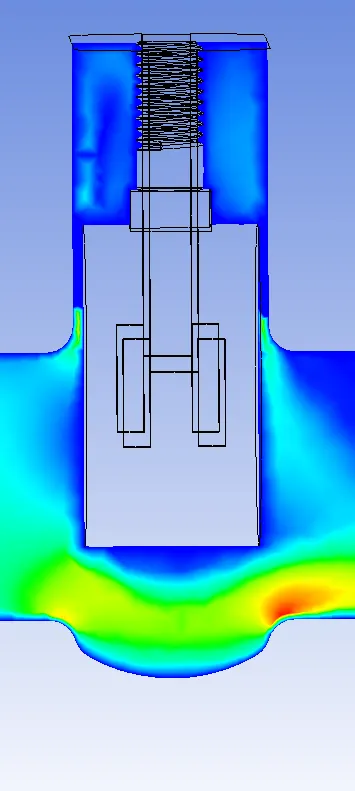
For 50% (27.5 mm) lift of the gate disc
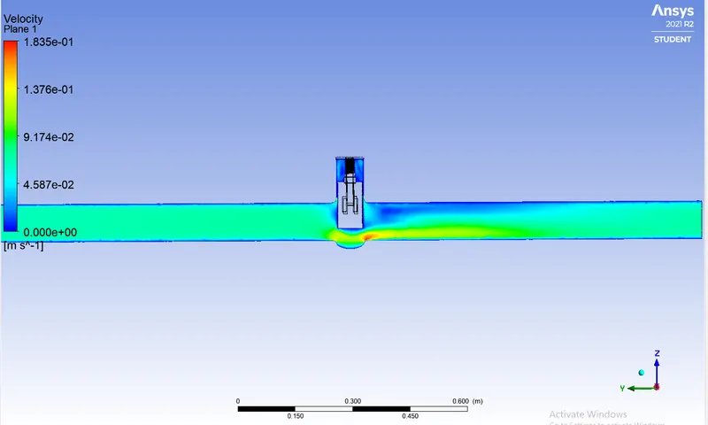
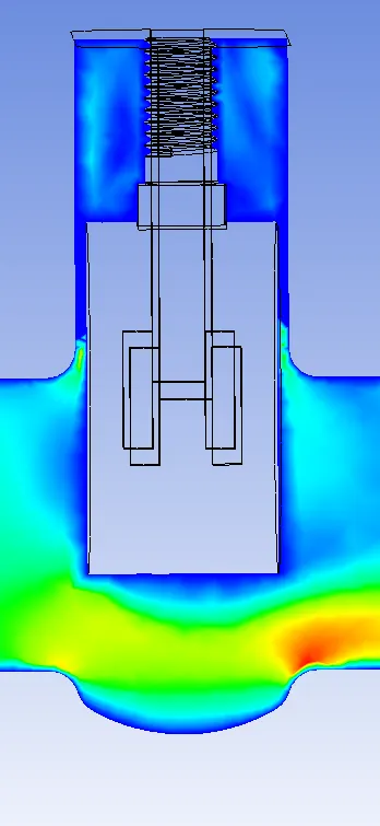
For 60% (33 mm) lift of the gate disc
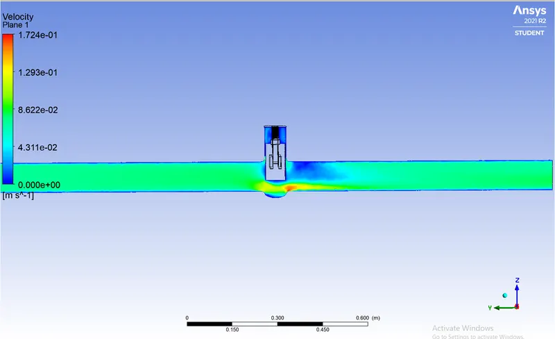
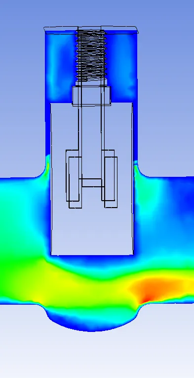
For 70% (38.5 mm) lift of the gate disc
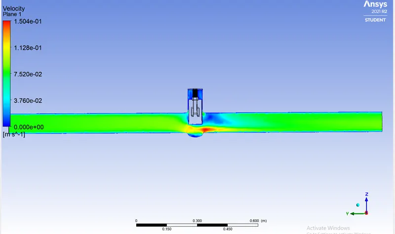
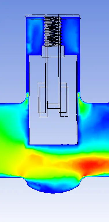
For 80% (44 mm) lift of the gate disc
CALCULATION:-
To calculate flow factor and flow coefficient
Flow factor
The metric equivalent flow factor (Kv; commonly used everywhere else in the world with the exception of the United States) is calculated using metric units :

where
- Kv is the flow factor (expressed in
 ).
). - Q is the flow rate (expressed in cubic meters per hour [
 ]),
]), - SG is the specific gravity of the fluid (for water = 1),
- ∆P is the differential pressure across the device (expressed in [bar]).
Kv can be calculated from Cv using the equation:

Flow coefficient

Kv can be calculated from Cv using the equation:
| percentage | mm | Q in kg/s | Q in m^3/h | sg of water | ∆p in bars | sg/∆p | √sg/∆p | Flow factor | Flow coefficient |
| 10% | 5.5 | 0.19303 | 0.695 | 1 | 0.0001 | 10000 | 100 | 69.5 | 80.34682081 |
| 20% | 11 | 0.25024 | 0.901 | 1 | 0.0001 | 10000 | 100 | 90.1 | 104.1618497 |
| 30% | 16.5 | 0.31515 | 1.135 | 1 | 0.0001 | 10000 | 100 | 113.5 | 131.2138728 |
| 40% | 22 | 0.38462 | 1.385 | 1 | 0.0001 | 10000 | 100 | 138.5 | 160.1156069 |
| 50% | 27.5 | 0.45424 | 1.635 | 1 | 0.0001 | 10000 | 100 | 163.5 | 189.017341 |
| 60% | 33 | 0.51798 | 1.865 | 1 | 0.0001 | 10000 | 100 | 186.5 | 215.6069364 |
| 70% | 38.5 | 0.55675 | 2.004 | 1 | 0.0001 | 10000 | 100 | 200.4 | 231.6763006 |
| 80% | 44 | 0.60459 | 2.177 | 1 | 0.0001 | 10000 | 100 | 217.7 | 251.6763006 |
OBSERVATION:-
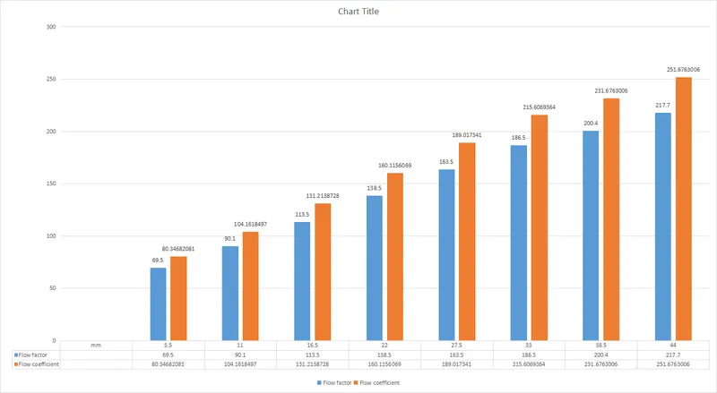
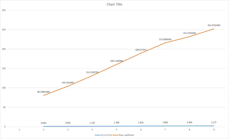
- Mass flow rate gradually increases as the lift of the gate disc is increased.
- And also increase in flow coefficient to the increase in mass flow
- The variation of flow coefficient and flow factor with the opening of the valve is studied by using parametric.
- A parametric study is a time-reducing option when studying the effects of changes of certain parameters on a system.
- Flow coefficient plays important role in the selection of valve and sizing of a valve, so calculating it is necessary.
- flow coefficient also helps in computing the efficiency of the system and the effect of pressure on the system.