Week 9 - Mini project - Flow over an Airfoil
introduction
The cross-sections of wind turbine blades have the shape of airfoils. The airfoils are structures with specific geometric shapes that are used to generate mechanical forces due to the relative motion of the airfoil and a surrounding fluid [1]. The shape of the airfoil greatly influences the aerodynamic performance of wind turbines and therefore their efficiency. Taking into account the above, some key concepts are discussed in general.
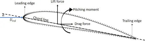
the chord line is the straight line connecting the leading and trailing edges and is designated as c. The thickness is the distance between the upper and lower surfaces and is perpendicular to the chord line. The camber is halfway between the top and bottom surfaces. The angle of attack (α) is defined as the angle between the relative wind and the chord line. The span is the length of the airfoil perpendicular to its cross-section. The geometric parameters that have an effect on the aerodynamic performance of an airfoil include the leading edge radius, mean camber line, the thickness distribution of the profile, and the trailing edge angle. These parameters are subject to constant study to obtain maximum aerodynamic performance in wind turbines.
The airflow over an airfoil produces forces over the airfoil surface, that is, lift, drag, and thrust forces. The airflow velocity is lower on the “pressure” side of the airfoil and accelerates, resulting in lower average pressure, on the “suction” side of the airfoil. Meanwhile, viscous friction between the air and the airfoil surface slows the airflow to some extent next to the surface The forces are defined as follows:
- lift force is defined perpendicularly to the direction of the oncoming airflow. It is a consequence of the unequal pressure on the upper (suction) and lower (pressure) airfoil surfaces.
- Drag force is defined parallel to the direction of the incoming airflow. This force is due to viscous friction forces at the airfoil surface and to unequal pressure on the airfoil surfaces facing toward and away from the incoming flow.
- Pitching momentum is defined to be about an axis perpendicular to the airfoil cross-section.
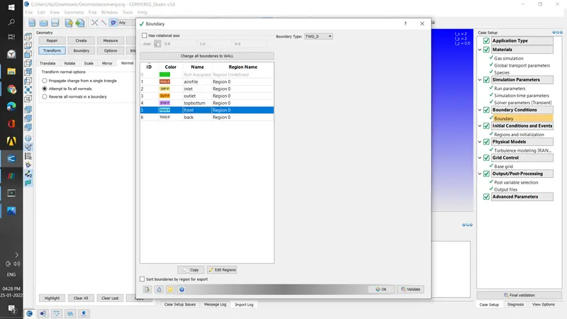
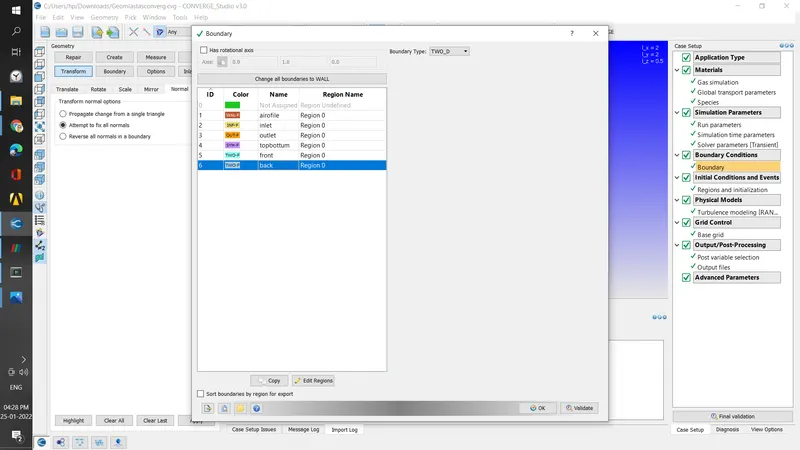
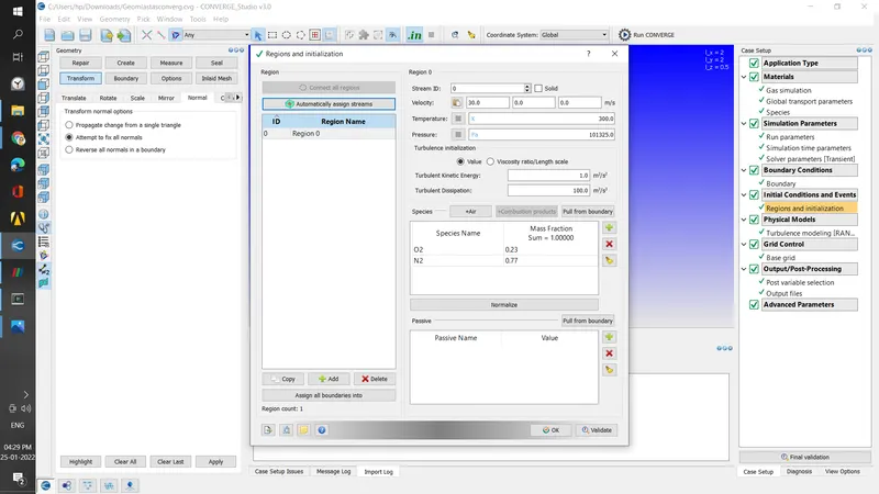
case setup
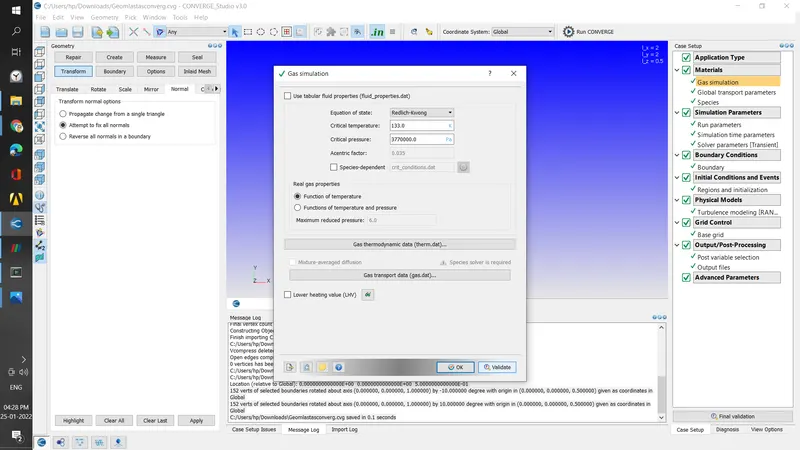
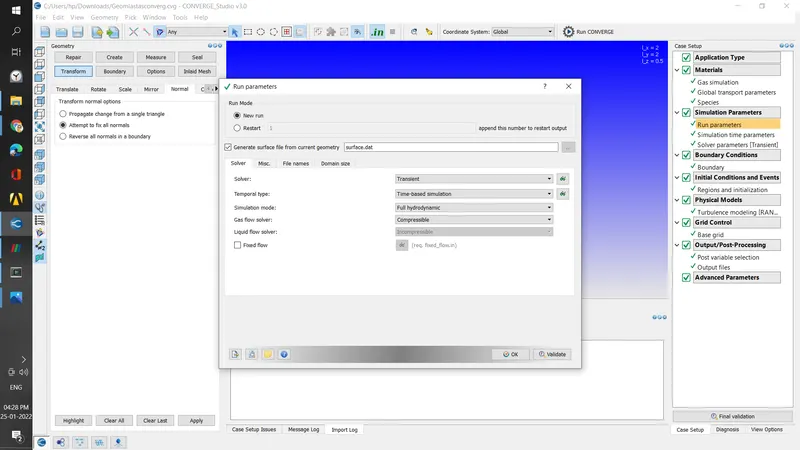
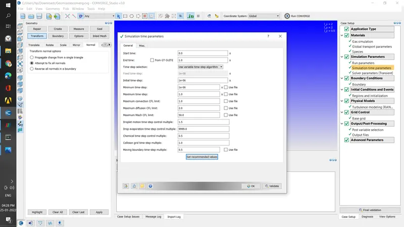
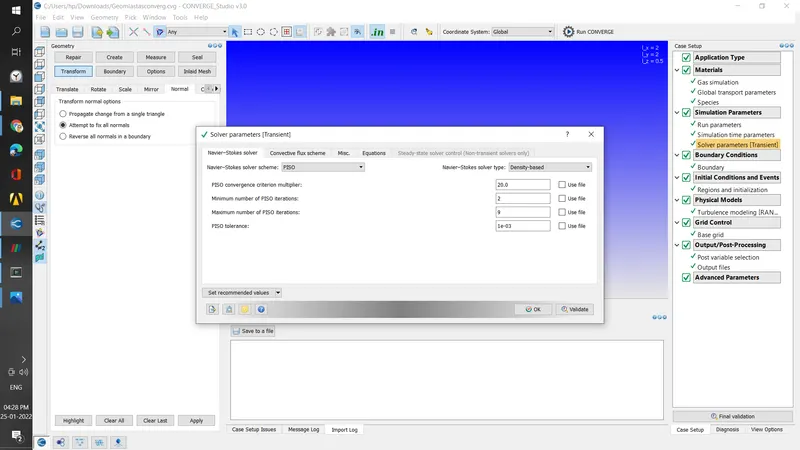
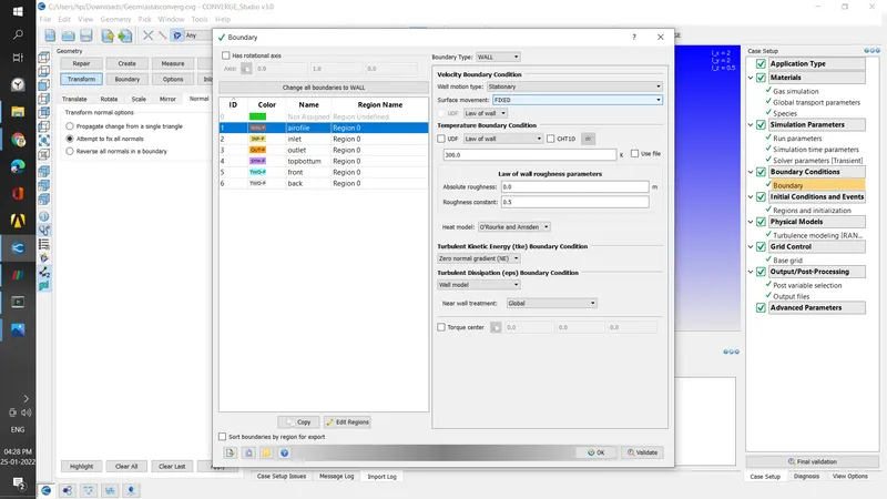
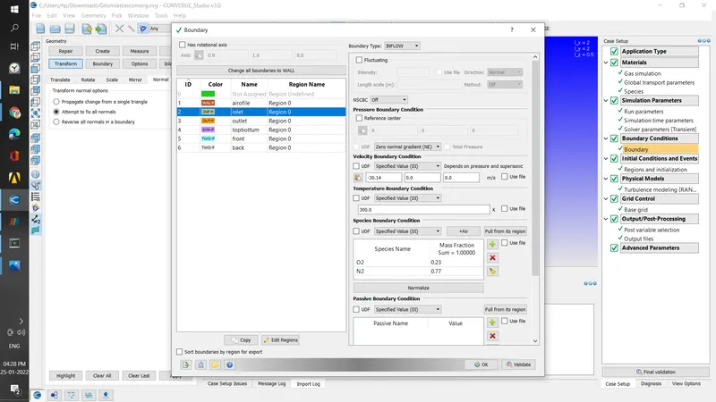
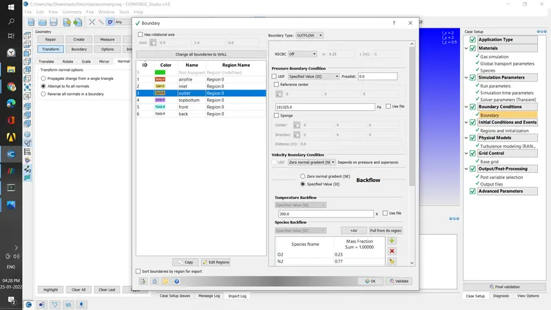
sample calculation cl and cd
CL = L/qS
q = (rU2/2)
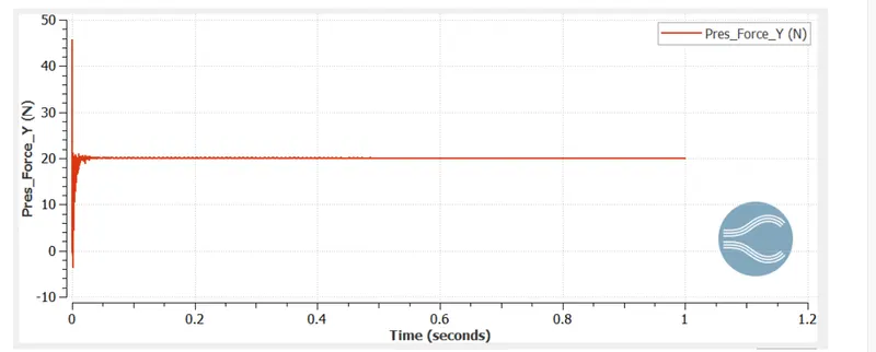
L=20 N S=0.1253
D=1.001
cl=2*20.0676/(1.255*30^2*0.1253)
cl=0.36038
cd =2*1.00305/(1.255*30^2*0.1253)
cd=0.01819
The angle of attack = 1º
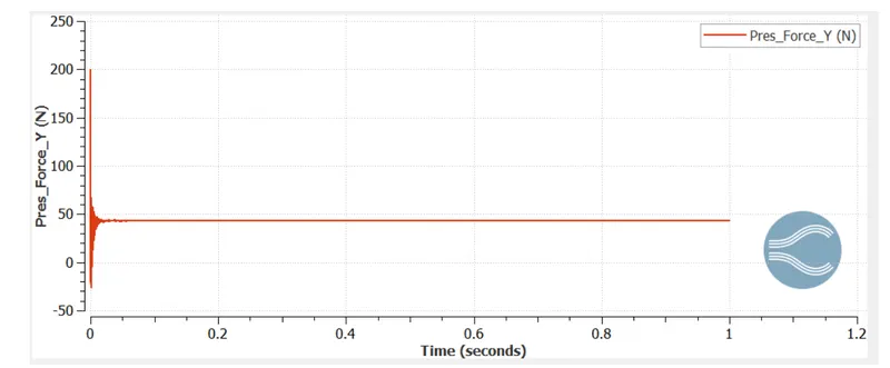
- The angle of attack = 5
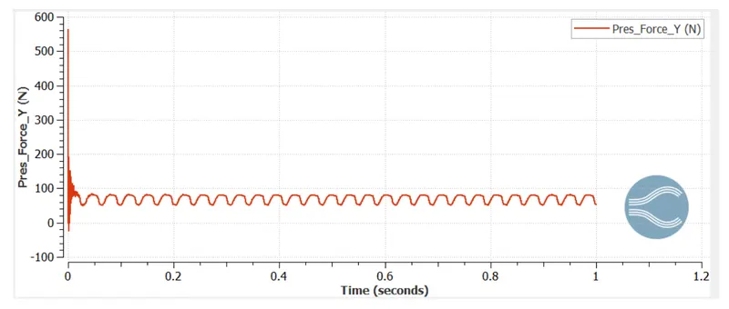
- The angle of attack = 10º
| angle | cl | cd |
| 1 | 0.364038 | 0.01819 |
| 5 | 0.78058 | 0.01958 |
| 10 | 1.25693 | 0.03055 |
| 15 | 0.9122 | 0.06365 |
cd vs AOA
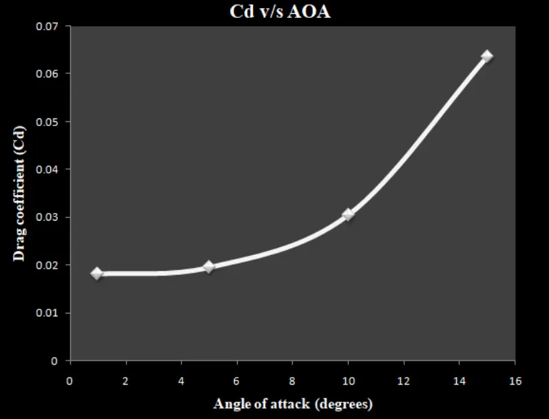
in case pf drag force the pressure drag component in the total drag is very less in case of profile till 10-degree angle of attack, after the 10-degree angle attack,the pressure drag increase
cl vs AoA
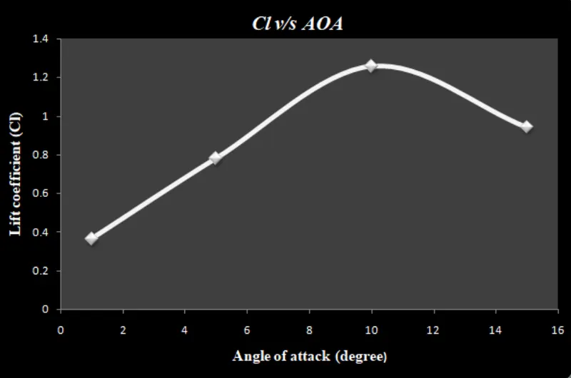
the coefficient lift increases with the increase in the angle of attack; after a certain angle of attack the coefficient of lift decreases
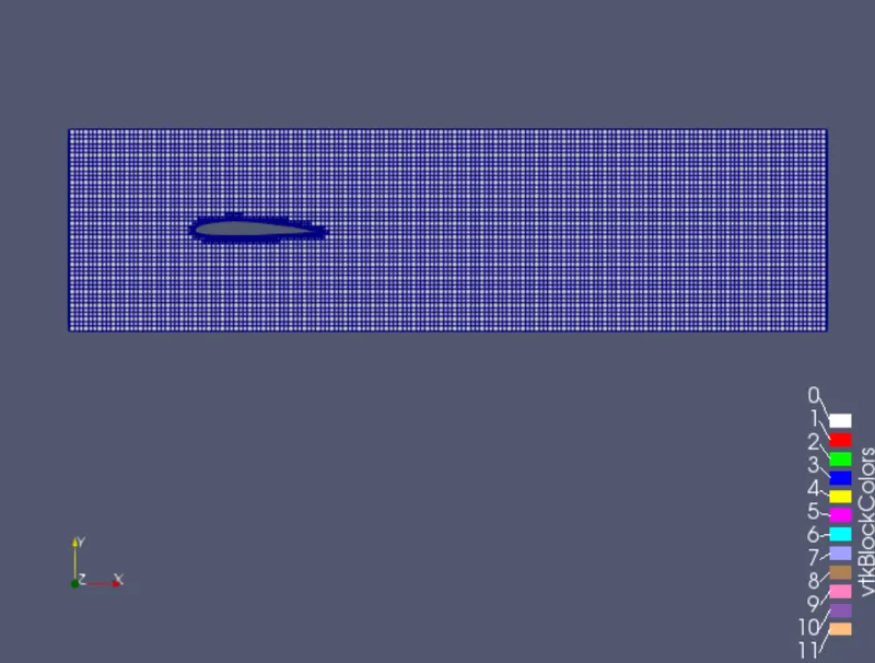
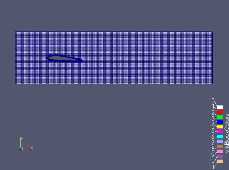
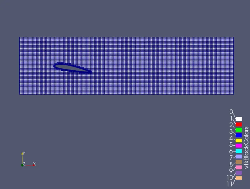
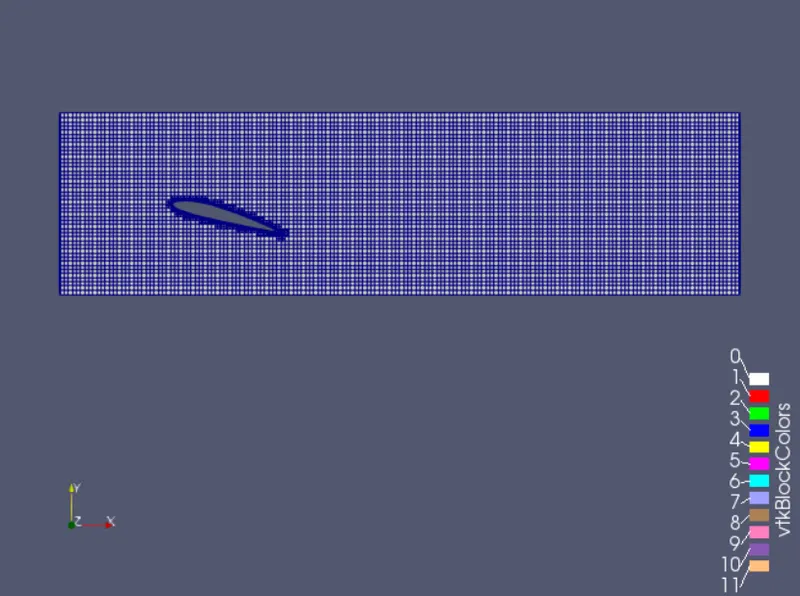
meshing
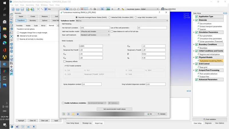
turbulence model
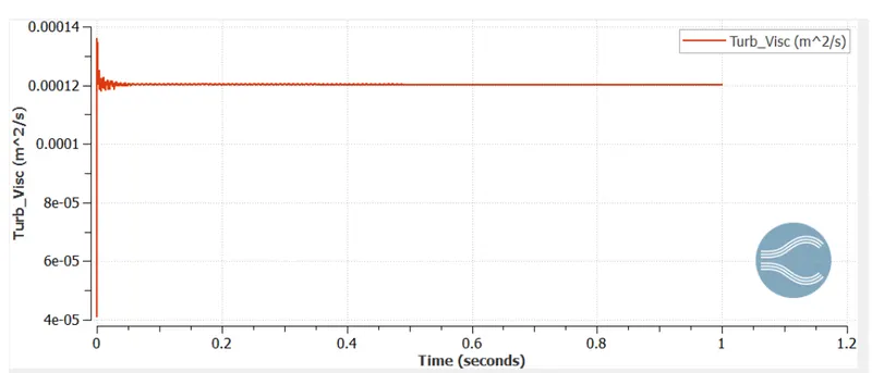
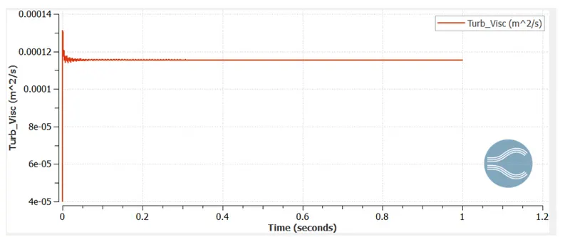
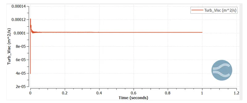
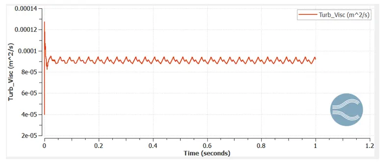
1 degree
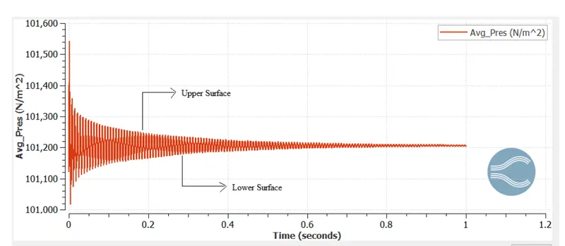
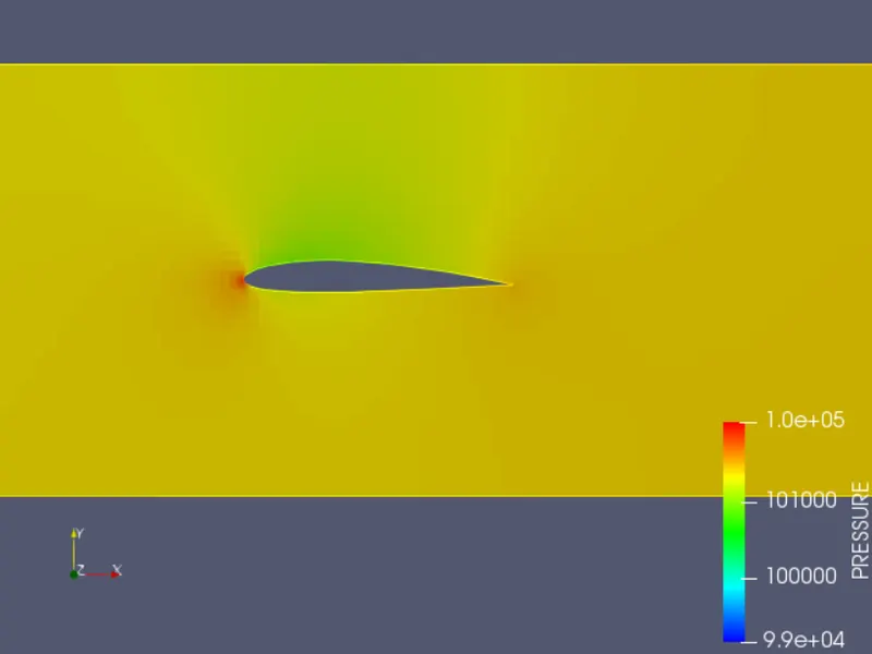
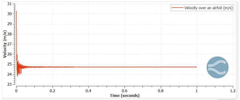
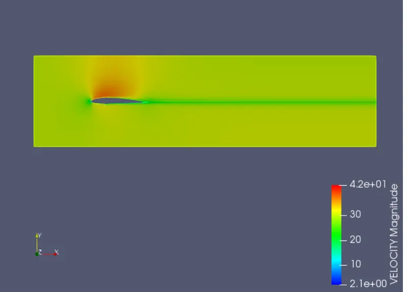
5 degree
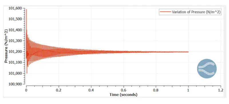
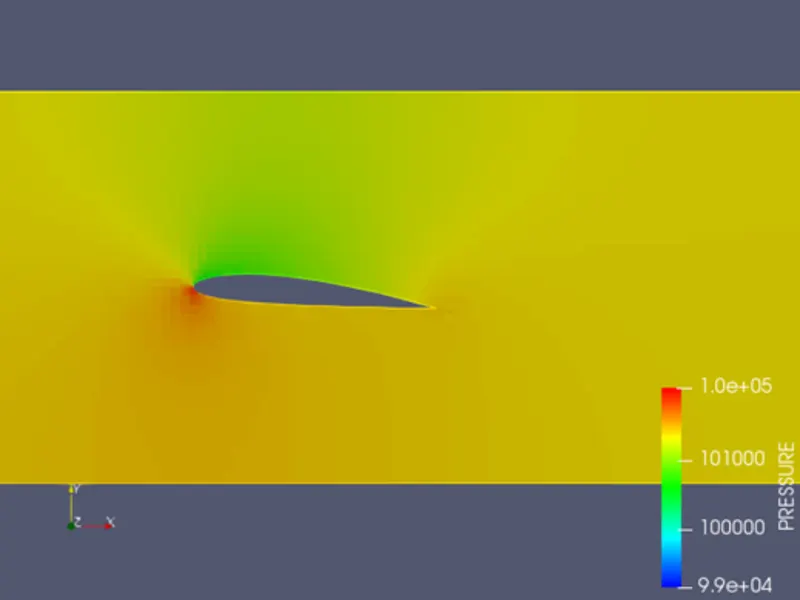
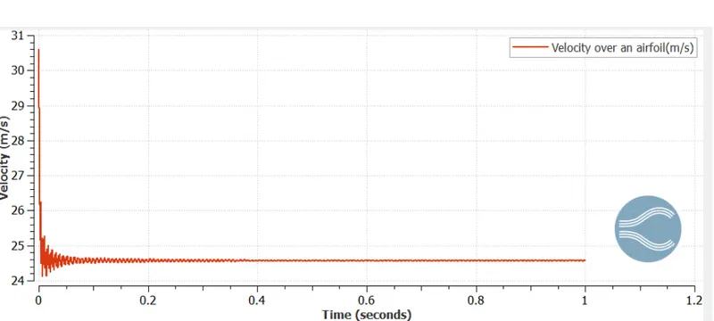
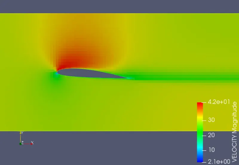
10
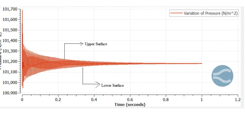
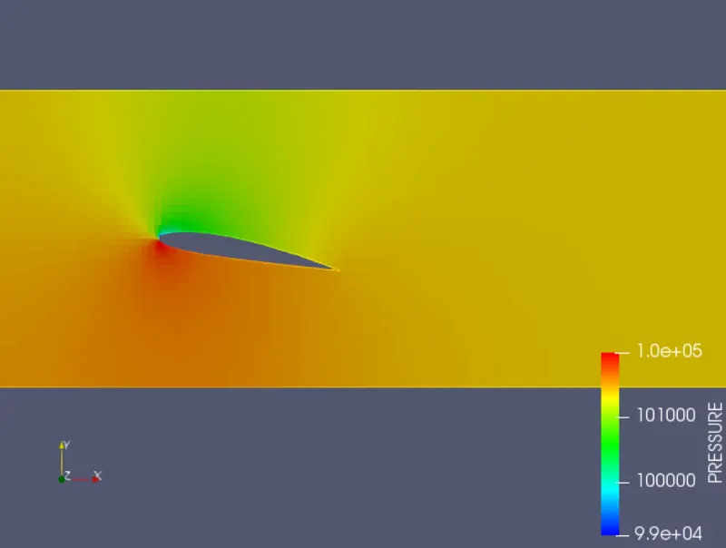
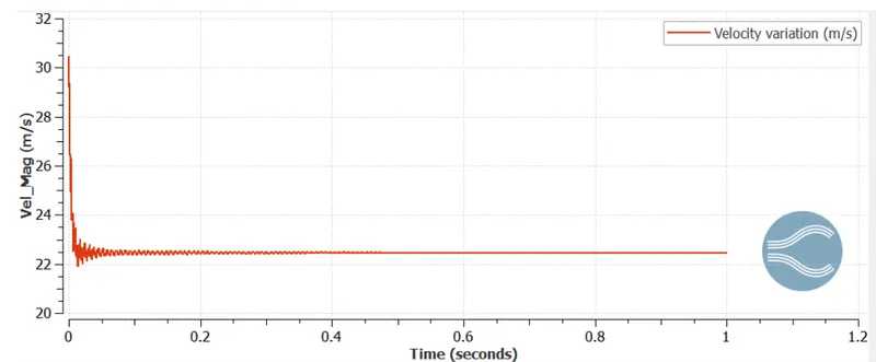
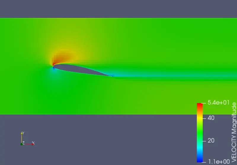
15
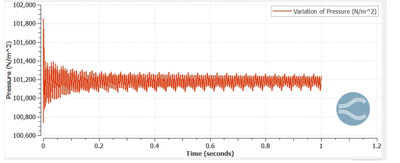
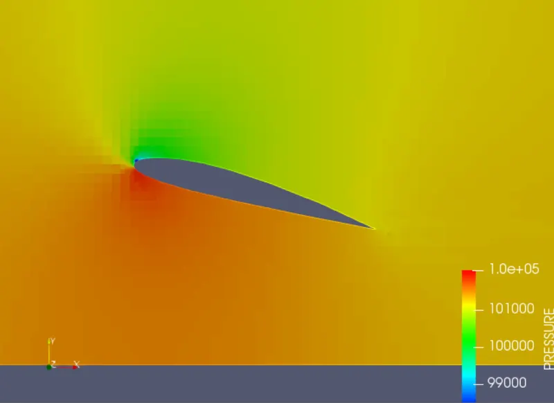
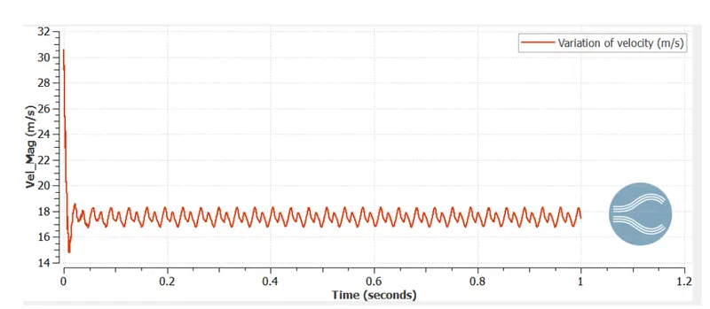
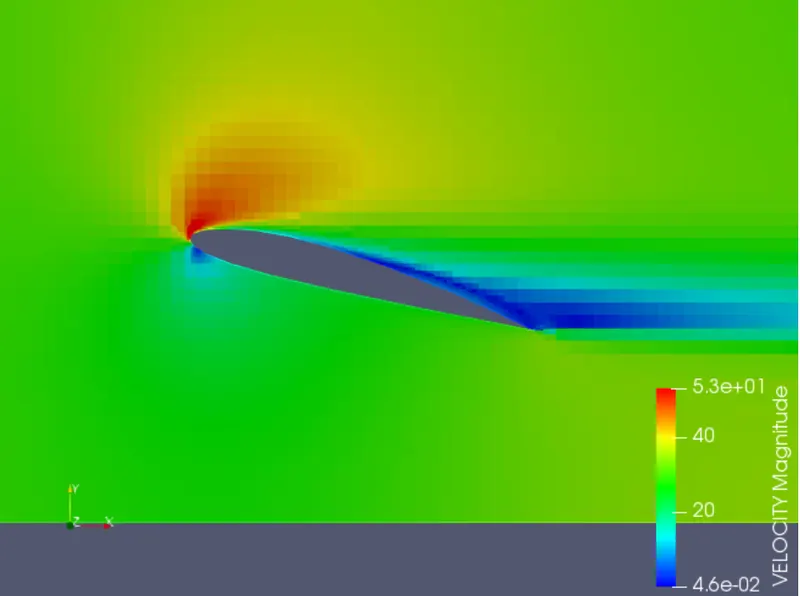
conclusion
the flow over NACA2412 aero file is done for various angles of attack
velocity and pressure variation across the profile is done