Week 9 - Mini project - Flow over an Airfoil
FLOW OVER AN AIRFOIL
What is an air foil? How doest it works?
Airfoil, also spelled Aerofoil, shaped surface, such as an aeroplane wing, tail, or propeller blade, that produces lift and drag when moved through the air. An airfoil produces a lifting force that acts at right angles to the airstream and a dragging force that acts in the same direction as the airstream.
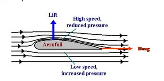
Objective-
- Simulate flow over a 4 digit airfoil i.e NACA 2412 Airfoil.
- Show plots of Drag co-efficient Vs Angle of Attack
- Show plots of Lift co-efficient vs Angle of Attack
- Compare the effect of turbulence models on the above two results.
- Make sure that the inlet Reynolds number is 200,000
- Make sure you do above calculations for the following angle of attacks,
- Angle of attack = 1º
- Angle of attack = 5º
- Angle of attack = 10º
- Angle of attack = 15º
Geometry
TTo get the desired geometry you have to use a pretty good converge tools knowlege, we have used NACA 2412 Airfoil. This airfoil coordinates are available on website link provided on the challenge page.
Steps to create geometry
- copy all vertex from website containing airfoil coordinate information and then join those vertex using openedge tool.
- you will get a 2D shape of airfoil , create a copy of that shape at certain distance from original.
- using openedge technique and using patch tool, path both surfaces to create 3D air foil.
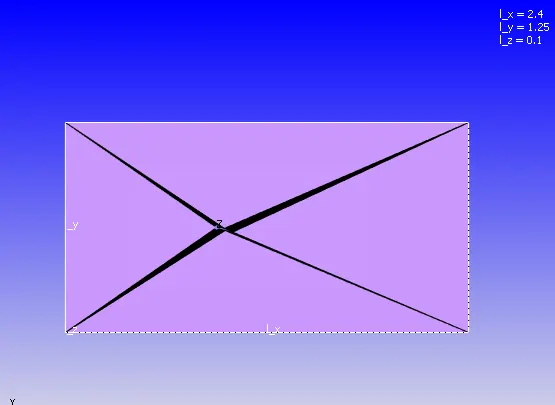
- Now we have to create a wind tunnel, to do this first create 4 vertices at four corners of air foil at a distance of 25 time chord length.
- chord length is the length of airfoil, so if chord length is 2.5m vertex should be at 25*2.5.
- create four veretx at four corners giving distance according to dimension of airfoil.
- after creating vertex join each vertex with with vertex of air airfoil using open veretx tool from create menu.
- we will create a 2D wind tunnel using patch and open edge tool.
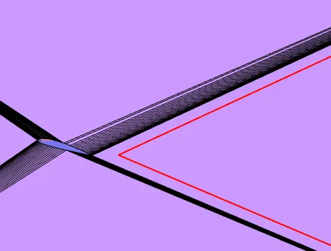
- we will delete the airfoil geometry after creating the wind tunnel , such that a hole of airfoil shape is left on wind tunnel.
- after that we will create a copy of wind tunnel and path its edges, using directional loft airfoil shaped open space we will create airfoil inside wide tunnel.
CASE SETUP-
Solver parameters
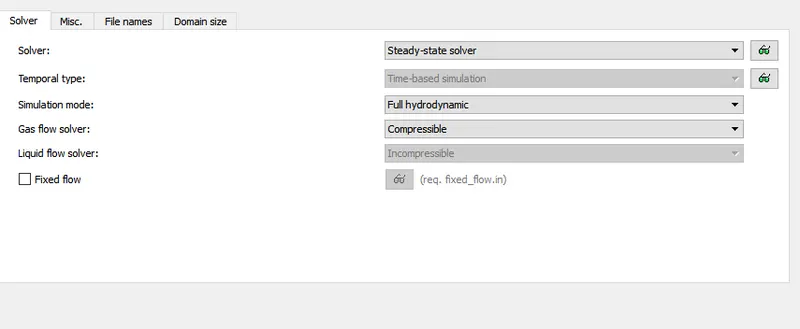
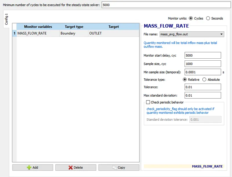
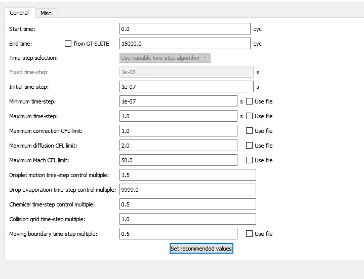
This a steady state simulation , we can easily capture all required effects on latest version of converge using steady state solver , hence we will not opt for transient state solver.
simulation would be of 15000 cycles in which initial time step is 1e-7.
Regions and initialisation-
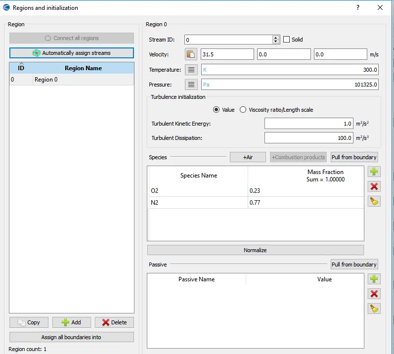
create a region which we will assign to boundary
Boundaries
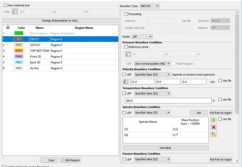
Inlet - we know velocity at inlet , we calculated velocity using reynolds number formula. For pressure there is neumann boundary condition
reynold's number = `(rho*v*l)/mu`
rho is density of air
v is unknown velocity
mu viscosity of air
l is length of geometry
reynold's number is 200000
Outlet - we dont know velocity at outlet so zero normal gradient boundary condition is used. pressure at outlet is atmospheric pressure.
Top - Bottom - This is symmetric, leave all condition as default .
Front and back - both are 2D walls
Airfoil - wall boundary condition is used because we want to capture velocity and pressure movements at boundary.
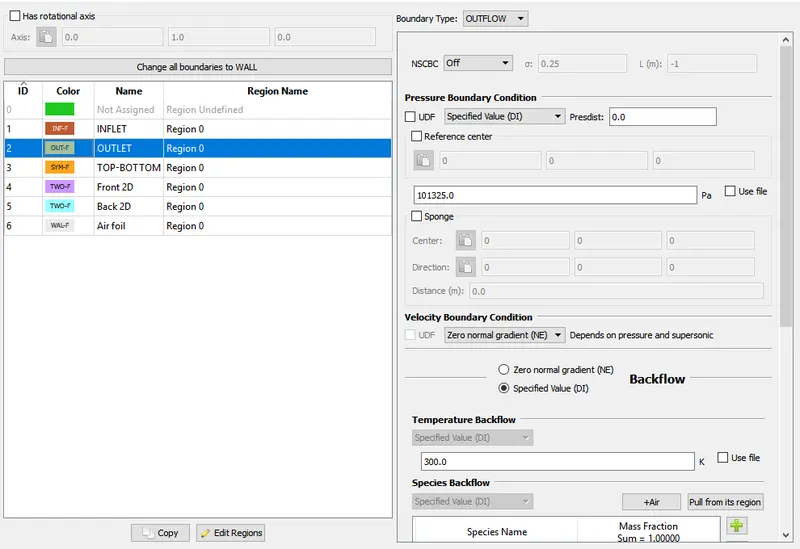
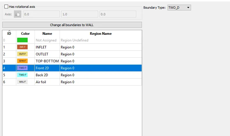
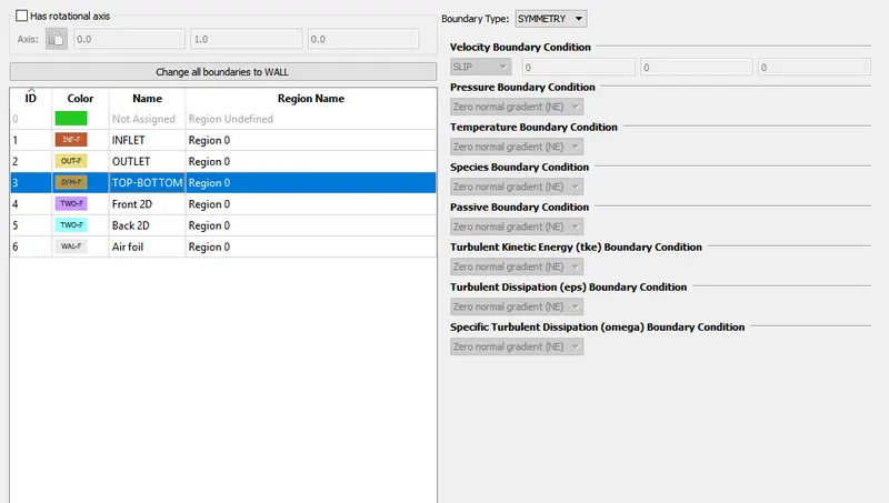
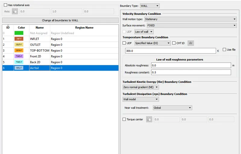
Base grid
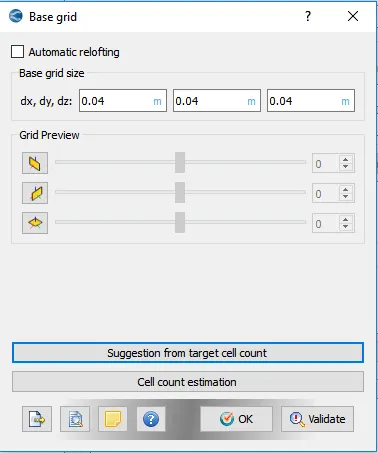
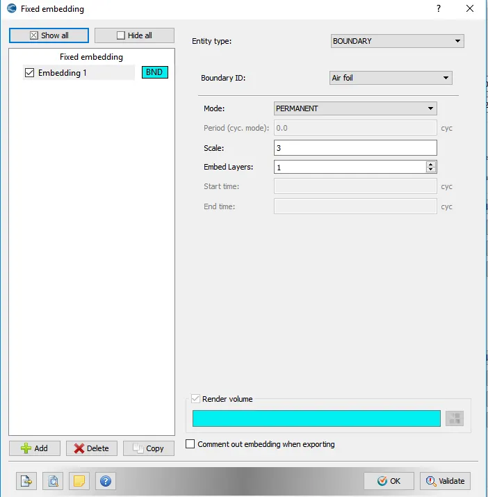
Fixed embedding is used around boundary of airfoil to create more finer meshes , so data around airfoil boundary is calculated more efficiently.
PLOTS-
drag force - This is the pressure force created when object moves at certain velocity , this force contributes in reducing velocity and increases friction force faced by front head of vehicles.
Lift forces - This force contributes in takeoff of airplanes and other flying objects. lift force acts vertically on body of vehicles while drag force is horizontal force .
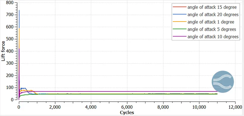
Lift force plot
As we can see in plots lift force is not propotional to angle of attack. lift force for 10 degree angle of attack is more than 20 degree angle of attack.
we can assume that lift force increases with increase in angle of attack but it also drops when angle of attack exceeds certain value.
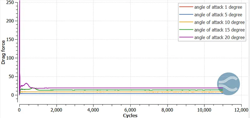
Drag force -
DRag force on other hand increases with increase in angle of attack, it is directly proportional to degree of angle of attack.
drag force is lowest for angle of attack 1 degree whereas it is highest for angle of attack of 20 degrees.
Animation
Angle of attack 1 degree
velocity does not fluctuates much at this angle of attack and flow seems to be smooth. vertical forces are quite low.
https://drive.google.com/file/d/1bGJ7BxJlJx7aUviTK55cw3lP3RI6PZKd/view?usp=sharing
Angle of attack 5 degree
https://drive.google.com/file/d/1bGJ7BxJlJx7aUviTK55cw3lP3RI6PZKd/view?usp=sharing
Angle of attack 10 degree
https://drive.google.com/file/d/1My5G_INhUKbWS1glstAK94DcuxgO8FW8/view?usp=sharing
Angle of attack 15 degree
https://drive.google.com/file/d/1c3USyVN6mBTujanAMrsaggxEW5MEY3K3/view?usp=sharing
Angle of attack 20 degree
velocity fluctations are highest at 20 degrees
https://drive.google.com/file/d/1CPA8eSkIkP42_m-FRTc5qVT_UaOsZe0b/view?usp=sharing
Conclusion-
- different vehicles have different dimension of airfoil dimension according to their loads.
- lift force not proportional to angle of attack , it increase up to certain value of angle but then decreases if angle of attack increases more than that.
- drag force is directly proportional to angle of attack.