Week 9 - Mini project - Flow over an Airfoil
FLOW OVER AN AIRFOIL
AIM: To perform steady and Transient simulation over a NACA 2412 Airfoil for varying angle of attacks.
OBJECTIVE:
To calculate the following,
- Drag co-efficient Vs Angle of Attack
- Lift coefficient vs Angle of Attack
- Compare the effect of turbulence models on the above two results.
- Make sure that the inlet Reynolds number is 200,000
- Make sure you do the above calculations for the following angle of attacks,
- The angle of attack = 1º
- The angle of attack = 5º
- The angle of attack = 10º
- The angle of attack = 15º
THEORY
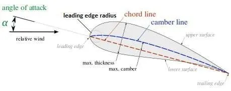
The above image shows the standard nomenclature of an airfoil.
Aerofoil is the cross-section of the wing normal to the span. The span of the wing is the lateral length of the aircraft. the distance between the two tips of the aircraft is called the span. The camber of the upper surface is more pronounced than the camber of the lower surface which is a lot flatter. The angle of attack: It is the angle between the relative wind and the chord line. A chord is a distance between the leading edge to trailing edge
Aspect ratio: The ratio between the wingspan and the mean chord is called the aspect ratio.
An aerofoil is a streamlined body designed in such a way that the separation occurs at the extreme rear end of the body. Such that it produces a small wake and subsequently small pressure drag. Even for a high Reynolds number, the pressure drag is very small, the skin friction drag makes a major contribution to the drag component as a whole. In the case of aerofoils, the resultant force is perpendicular to the direction of the flow. It is called a lift.
In the case of NACA 2412, the first two digits, signify the camber of the aerofoil and the last two digits signifies the thickness. The aerofoil is 12% thick and the maximum camber is 0.02c at x=0.04c, c denotes the chord length.
If we apply Bernoulli's principle at two sections of the aerofoil, The upper part and the lower part.
`(P_u)/(rho)+(0.5*V_u^2)=(P_l)/(rho)+(0.5*V_l^2)`
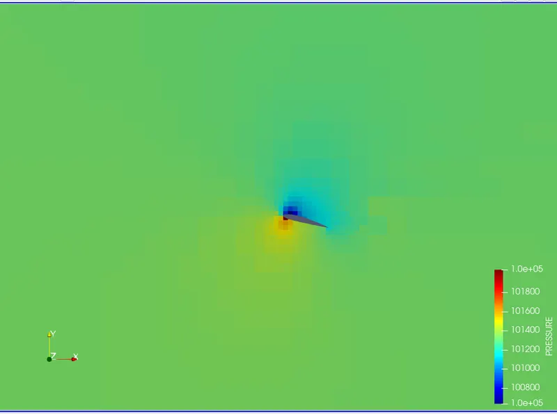
here, `P_u, V_u` denotes the pressure and velocity at the upper section and `P_l, V_l` denotes the pressure and velocity at the lower part. The velocity at the upper part is more than the velocity of the lower part. So, the pressure at the upper part is less than the pressure at the lower part. This pressure difference created generates the lift in the aerofoil.
The lift coefficient , `C_l=(F_l)/(0.5*rho*V^2*A_p)`
here, `F_l`is the lift force, `A_p` is the area of the frontal projection.
Similarly the drag coefficient is given by: `C_d=(F_d)/(0.5*rho*V^2*A_p)`
Here `F_d`is the drag force.
SIMULATION AND SOLUTION
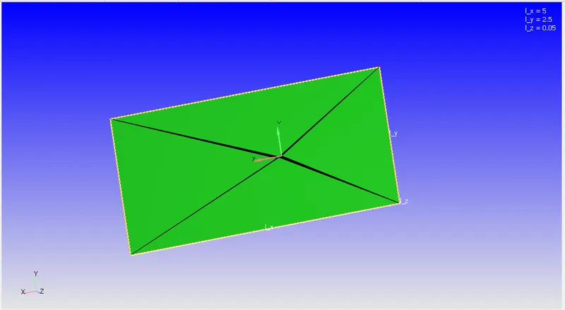
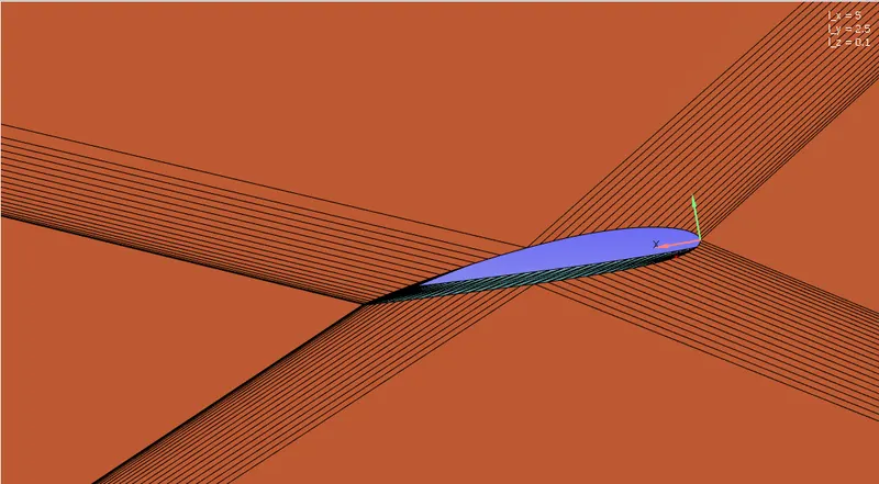
In this project, we consider the given airfoil vertices and create a geometry in coverage. We also create a flow tunnel to calculate the date, which is 50 times the cord length(0.01m). Making the negative X-axis front the point of origin 2m, X-axis in the positive direction is 3m, the positive and negative Y-axis being 1.25m, and the Z-axis as 0.1m.
Geometry:
Setup
|
Application Type |
Time-based |
|
MATERIALS: |
|
|
1. Gas simulation |
Standard |
|
2. Global Transport Parameters |
Standard |
|
4. Reaction Mechanism |
1. fluid: O2 and N2 |
|
SOLUTION PARAMETERS |
|
|
1. Run Parameters |
Transient >Full hydrodynamic>Compressible |
|
2. Simulation time parameters |
|
|
3. Solver parameters |
Navis-stokes solver scheme: PICO Navis-stokes solver type: density-based |
|
BOUNDARY CONDITIONS |
 |
|
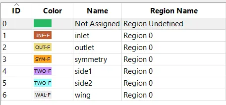
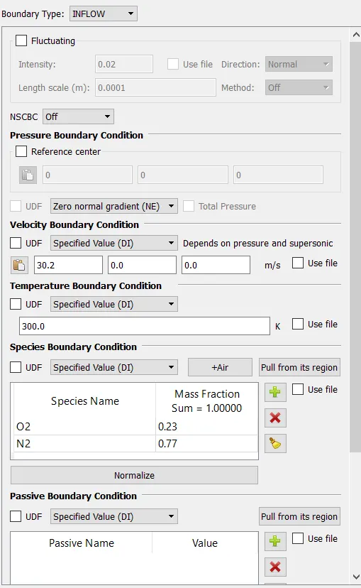
1. Inlet |
`Re = 200000 = (rho*v*L)/mu` Where - `rho` is air density `v` is air velocity `L` is the characteristic length, chord length in our case. `mu` is the dynamic viscosity of Air. 2) `v = (Re*mu)/(rho*L) = (200000*1.85e-5)/(1.225*0.01)= 30.2`m/s |
| 2. Outlet | 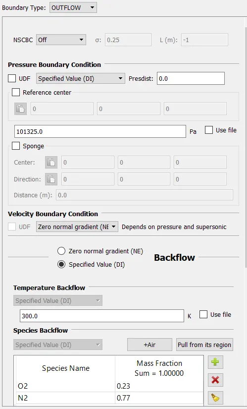 |
|
3. Symmetry |
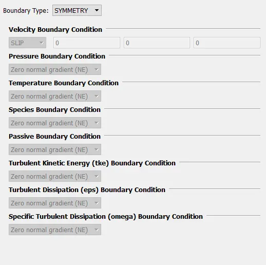 |
|
4. Sidewall 1 |
2D wall |
|
5. Sidewall 2 |
2D wall |
|
6.Wing |
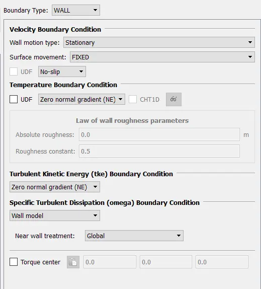 |
|
INITIAL CONDITIONS AND EVENTS |
|
|
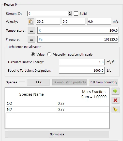
1. Regions and initialization |
|
|
PHYSICAL MODELS |
|
|
1 Turbulence modeling |
k-omega SST |
|
GRID CONTROL |
|
|
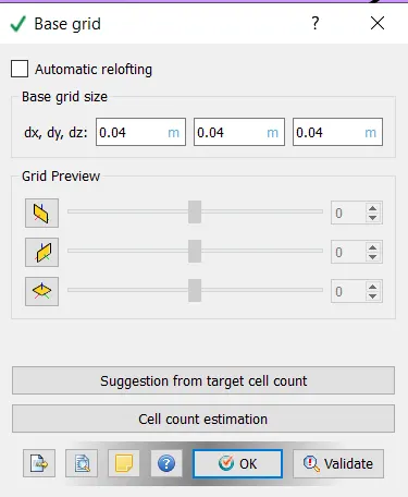
1. Base mesh |
|
|
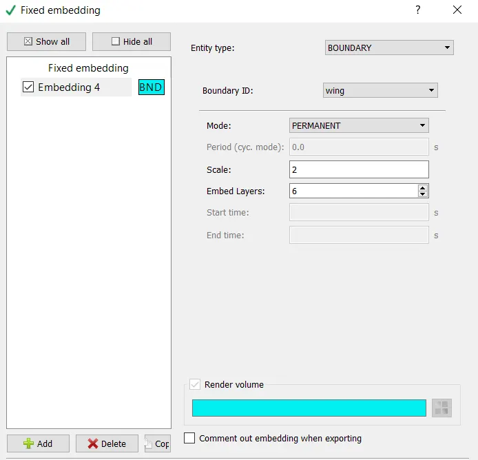
2. Fixed meshing |
|
|
OUTPUT/POST-PROCESSING |
|
|
1. Post variable selection |
Standard |
|
2. Output files: |
|
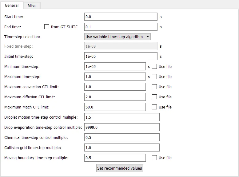
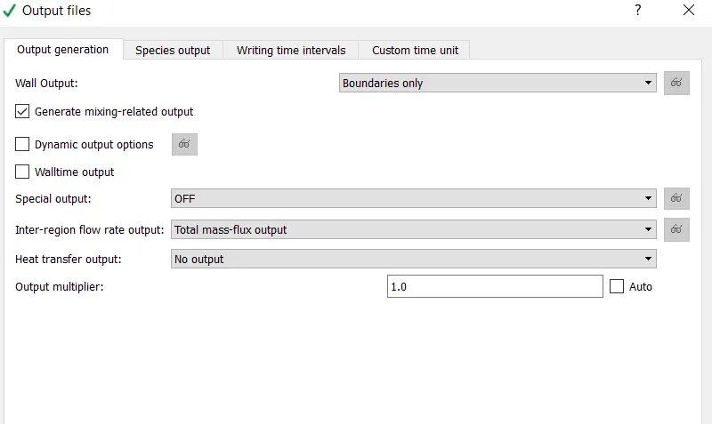
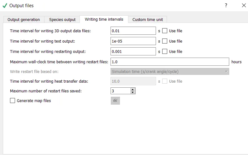
Then Export the Files
Then continuing the setup in Cygwin :
- leading to the folder where the exported files are saved
- Then using mpiexec.exe -n 2 converge.exe restricted to simulate the setup
- After the output is generated, we lead the Cygwin to the output folder, and by copying the post_convert folder and
- Using mpiexec.exe -n 2 post_convert.exe and converting these files for processable output in ParaView.
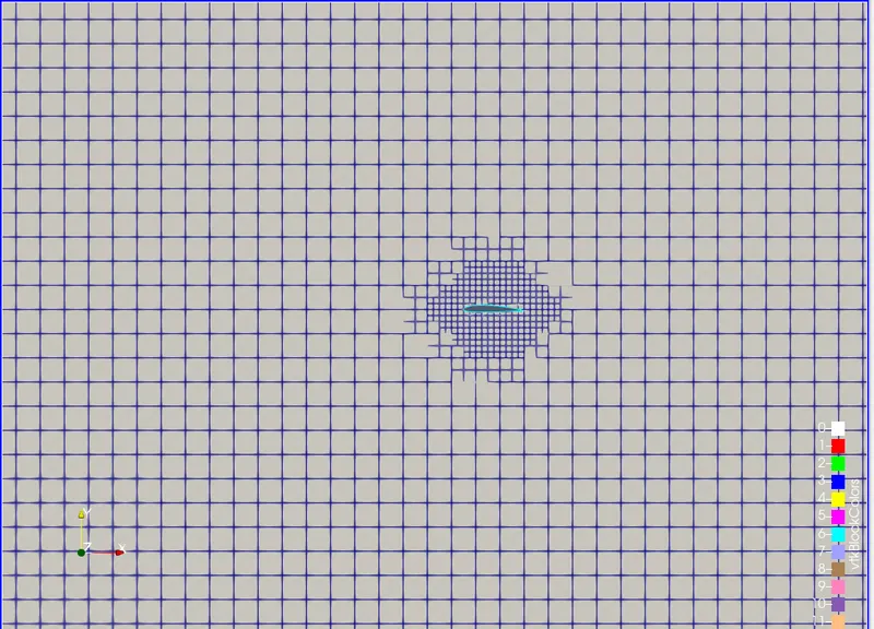
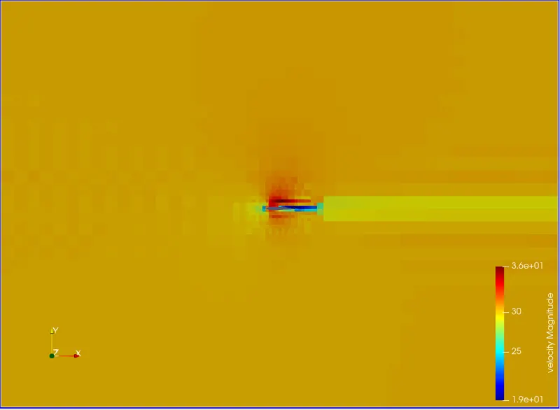
Case 1: Angle of attack 1 deg
Mesh
Velocity counter
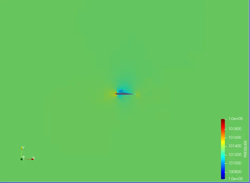
Pressure counter:
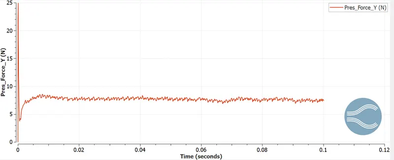
Lift force
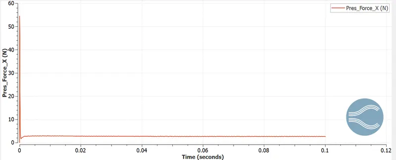
drag Force
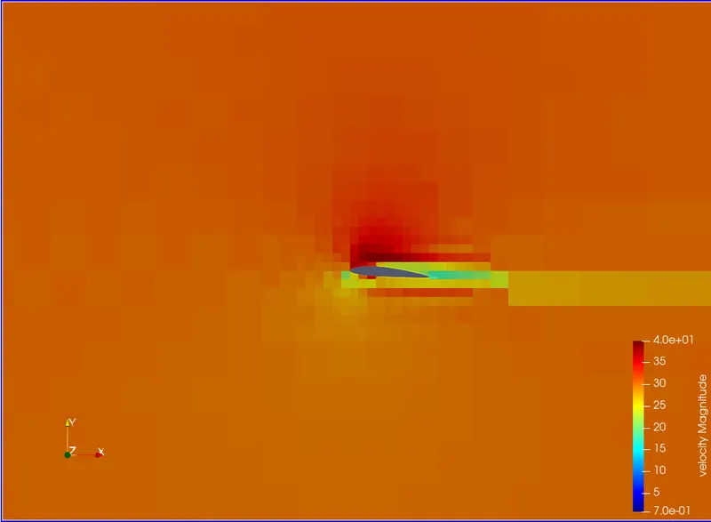
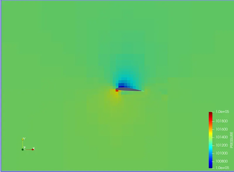
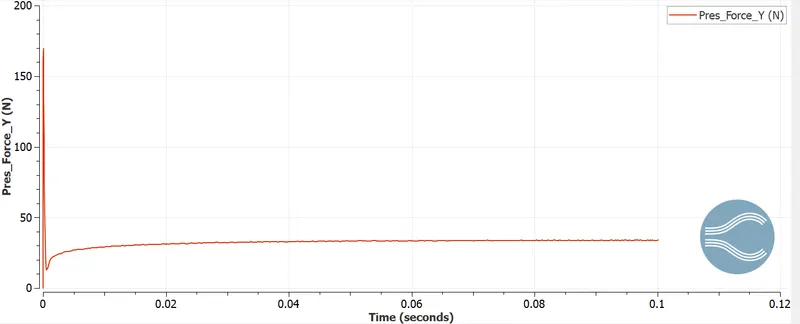
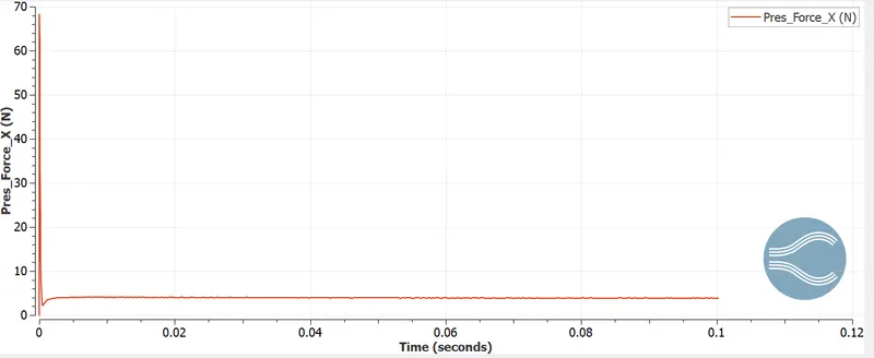
Case 2: Angle of attack 5 deg
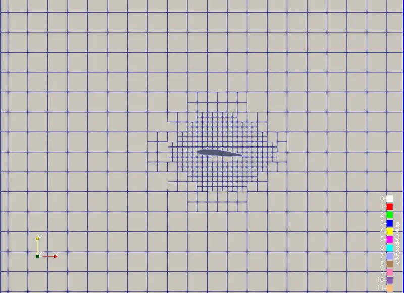
Mesh
Velocity counter
Pressure counter:
Lift force
drag Force
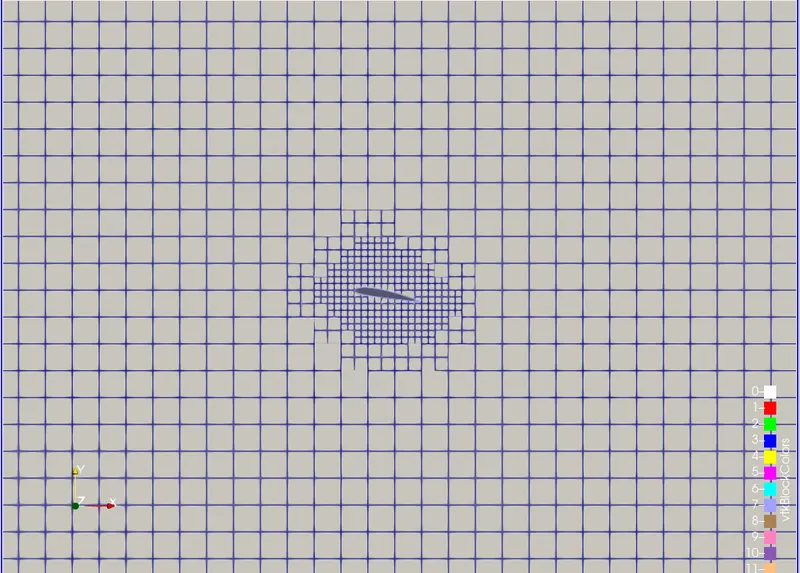
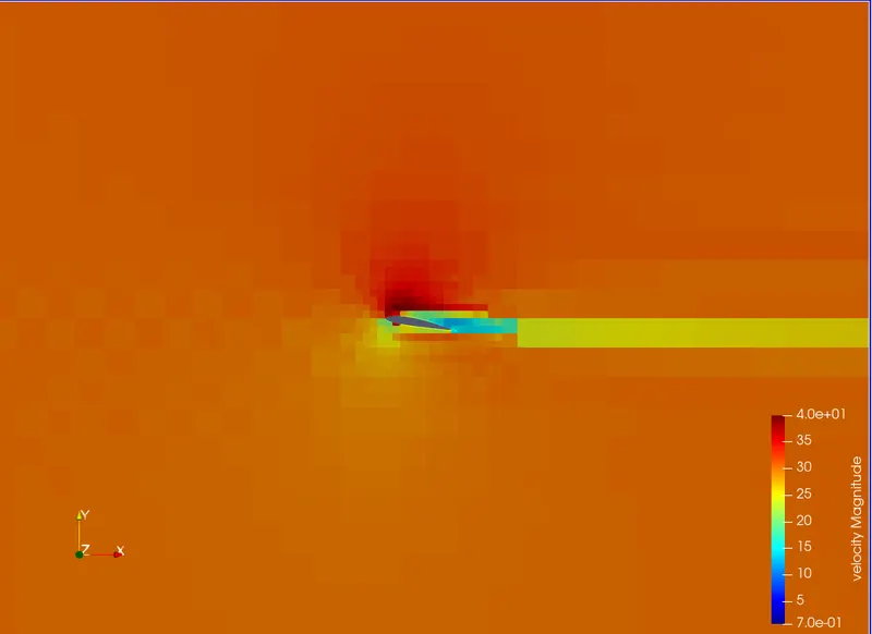
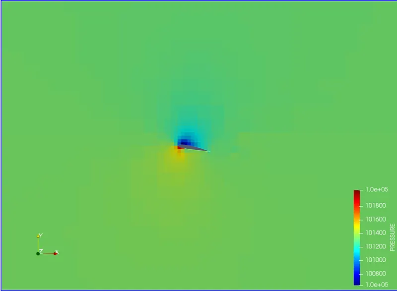
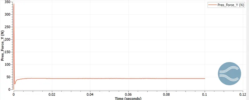
Case 3: Angle of attack 10 deg
Mesh
Velocity counter
Pressure counter:
Lift force
drag Force
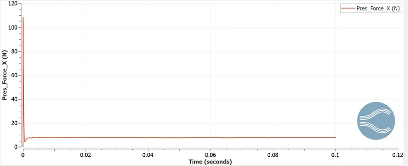
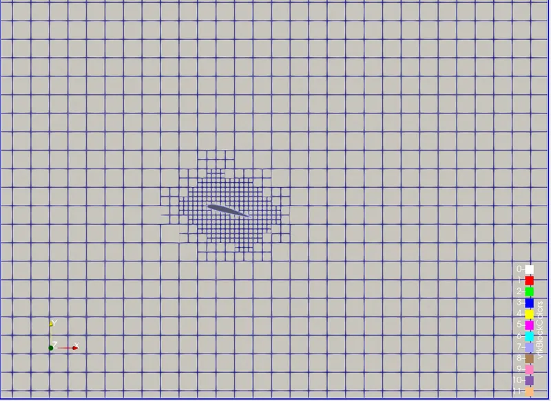
Case 4: Angle of attack 15 deg
Mesh
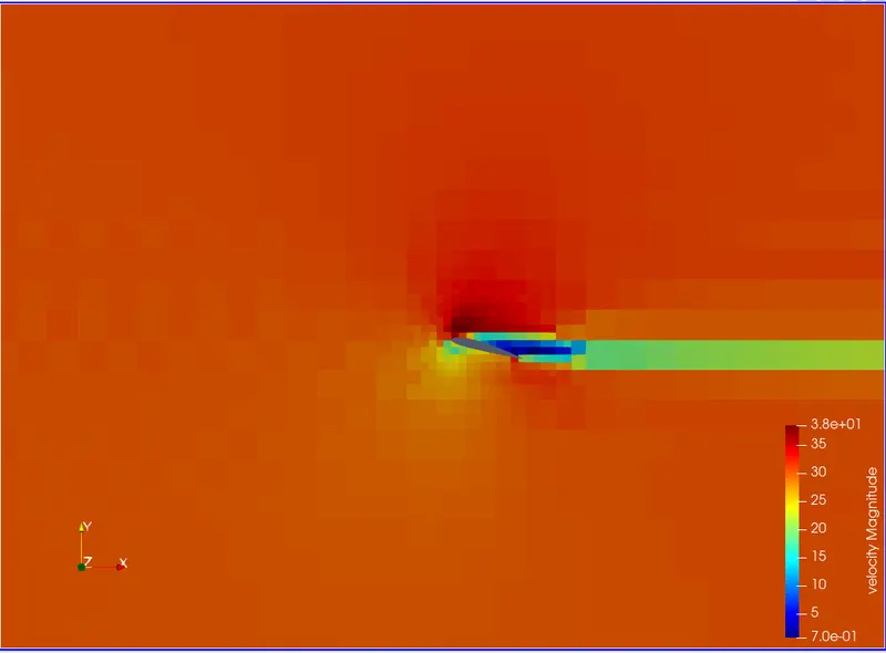
Velocity counter
Pressure counter:
Lift force
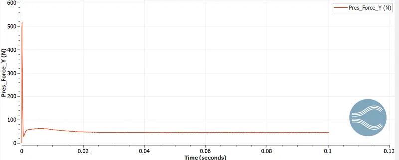
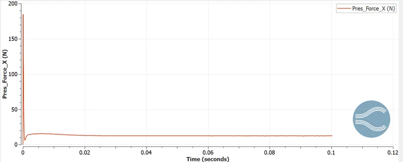
drag Force
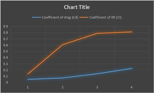
- Comparison of Coefficient of drag and lift with respect to the angle of attack:
- Using the formulas mention in the theory we calculate
- The lift coefficient , `C_l=(F_l)/(0.5*rho*V^2*A_p)`
here, `F_l`is the lift force is given below, where
`A_p` is the area of the frontal projection. (0.1m)
Similarly the drag coefficient is given by: `C_d=(F_d)/(0.5*rho*V^2*A_p)`
Here `F_d`is the drag force is given below.
-
`rho` is air density
`v` is air velocity 30.2 m/s
`L` is the characteristic length, chord length in our case.
`mu` is the dynamic viscosity of Air.
| AOA | Drag force (Fd) | Lift force (Fl) | Coefficient of drag (Cd) | Coefficient of lift (Cl) |
| 1 | 3.63 | 7.52 | 0.04707 | 0.1346 |
| 5 | 3.87 | 33.73 | 0.06927 | 0.6038 |
| 10 | 7.65 | 43.93 | 0.13694 | 0.7863 |
| 15 | 15.731 | 12.44 | 0.22260 | 0.8100 |
CONCLUSION
- The coefficient of lift increases with the increase in the angle of the attack. After a certain angle of attack, the coefficient of lift decreases. This phenomenon is called stalling condition.
- The dip in the lift force is due to the vortex formation in the leeward side of the aerofoil.
- in the case of the drag force, the pressure drag component in the total drag is very less in the case of the aerofoil till 10 degrees angle of attack. After the 10 degree angle of attack, the pressure drag increases significantly, due to the vortex formation. So the total drag increases.