Machining with Planer Using Ansys Workbench
OBJECTIVE
- To assign the structural steel material to the cutting tool, and steel 1006 to the workpiece.
- To mesh the model.
- To apply the boundary condition.
- To collect the results and interpret.
PROCEDURE
This simulation was an analysis of a shearing operation on a workpiece. The tool and workpiece model can be seen in the figure below. The simulation was solved using the explicit dynamics module of Ansys. The simulation was solved for two different cases. In the first case, the velocity of the machining was 20000 mm/s, while in the second it was 15000 mm/s.
 |
|
Figure 1: Workpiece and tool model in Ansys GUI. |
The Mesh section of the explicit dynamics module was opened. In that, the material of the tool was set to structural steel (default), and the material of the workpiece was set to steel 1006. Also, the stiffness behavior of the tool was changed to rigid. Further, the automatically detected contacts by Ansys were deleted, as it was not required.
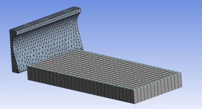
Next, the mesh was created for the model, as shown in the figure below.
 |
|
Figure 2: Meshing of the model. |
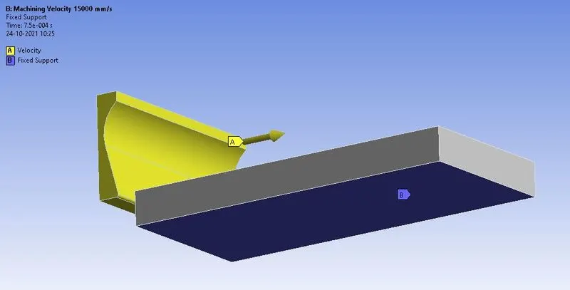
The analysis was solved for the end time of 7.5E-04 s. In boundary condition, the velocity of 20000 mm/s was applied to the tool, constrained to the x-axis only, and 15000 mm/s for the second case. And one face of the workpiece was fixed.
 |
|
Figure 3: Boundary condition for machining of the workpiece. |
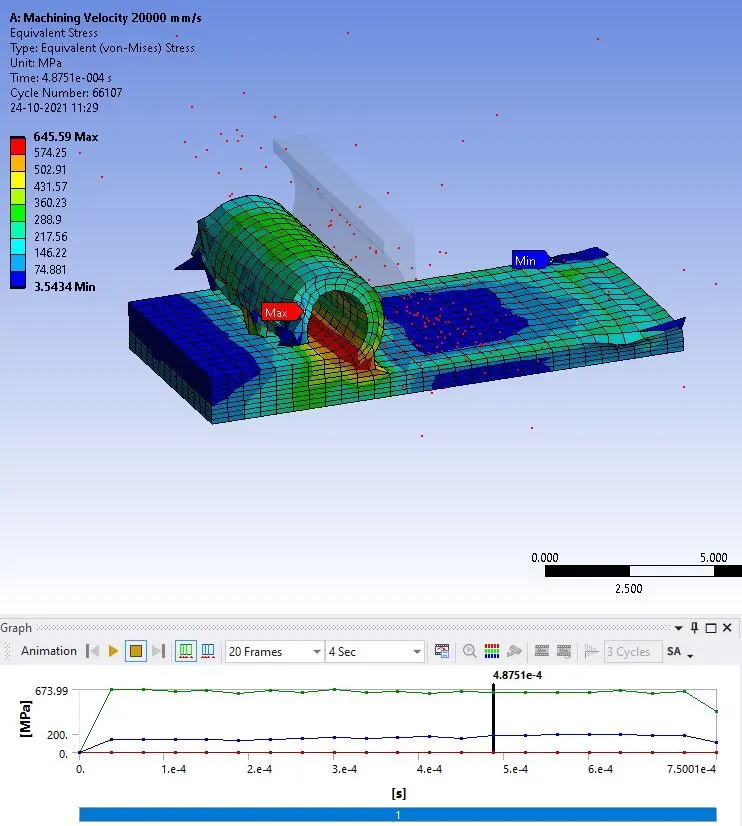
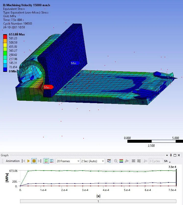
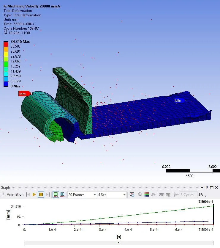
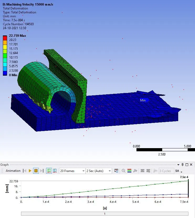
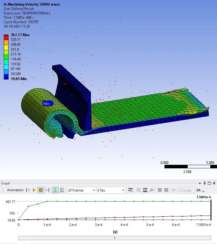
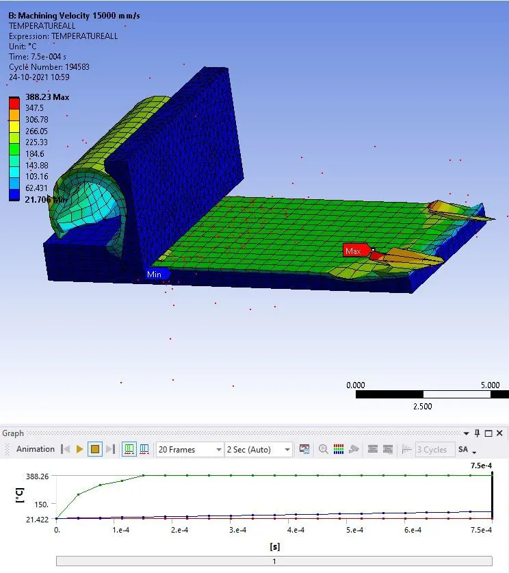
In the solution, the results were requested for the equivalent stress, total deformation, and temperature change. All the results are shown in the figures below, for both cases.
|
|
|
|
Figure 4: Equivalent stress in the model, when the velocity of machining was 20000 mm/s, and 15000 mm/s respectively. The maximum eq. stress in the first case was 673.99 MPa, while in the second it was 673.06. |
|
|
|
|
|
Figure 5: Total deformation in the model, when the velocity of machining was 20000 mm/s, and 15000 mm/s respectively. The maximum deformation in the first case was 34.316 mm, while in the second it was 22.759 mm. |
|
|
|
|
|
Figure 6: Temperature rise in the model, when the velocity of machining was 20000 mm/s, and 15000 mm/s respectively. The maximum temperature rise in the first case was 367.77 ºC, while in the second it was 388.23 ºC. |
|
CONCLUSION
This simulation was performed to study the procedure of simulating the machining operation. In this model, a workpiece was fixed, and a velocity was applied to the cutting tool, to shear the workpiece. It was found in the result that, the stress generation is almost similar in both the case. However, the temperature rise is more in the second case when the velocity of the cutting tool was 15000 mm/s, compared to the first case.