Week 9 Machining with Planer Challenge
- Objective: To perform dynamic explicit analysis of Machining with Planer tool for the given cases and compare the results.
Case 1: For cutting velocity of 2000 mm/s
Case 2: For cutting velocity of 1500 mm/s
- Procedure:
Open the explicit dynamic analysis system in the Project schematic. The material used for the analysis is explicit material - Steel 1006 Add the material in the material library. Now proceed to import the geometry.
Import the Geometry. Open the Geometry in SpaceClaim. Ensure the geometry is properly imported by doing quick visual inspection. The geometry is properly imported as observed.
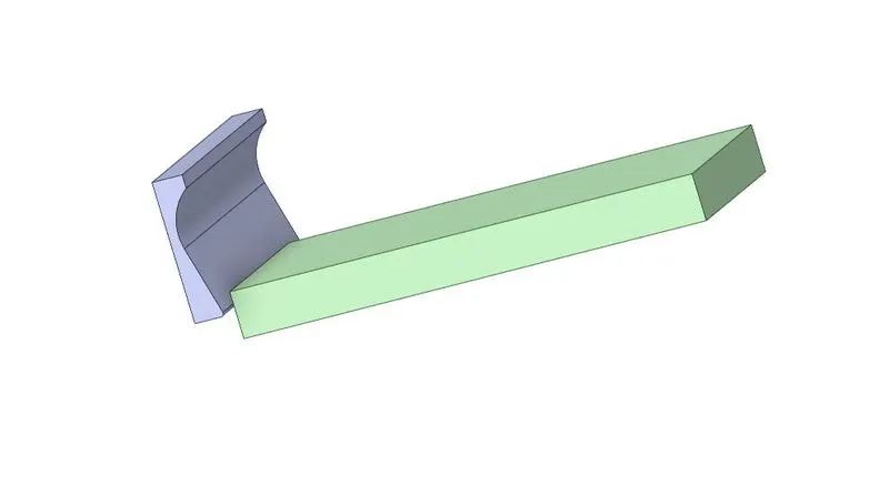
Update and open the mechanical module. Assign the material Steel 1006 for the workpiece. For The cutting tool, set the stiffness behavior to Rigid, since we are not concerned about the stress or other variables
acting on the tool.
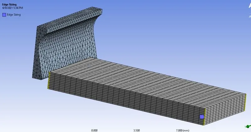
Delete any contact detected by the automatic contact detection between the cutting tool and the workpiece. Now mesh the model. First, insert method to mesh the cutting tool with Tetrahedrons. Go to
Connections > Insert > Method > Tetrahedrons.
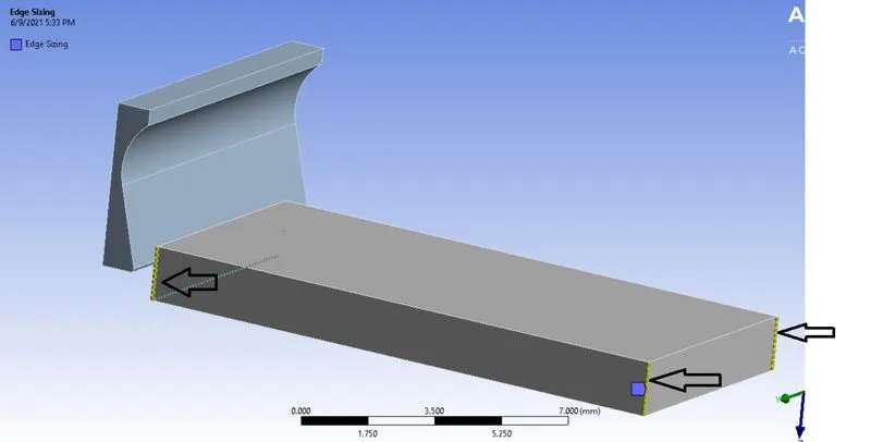
For the workpiece, the meshing is done using 10 layers across the thickness with the help of edge sizing. Go to Mesh > Insert > Sizing. In the Type selector, set the selector to No. of divisions. Enter no. of
divisions = 10. In the Geometry selector, select the 4 shortest edges as shown below and then mesh the component.
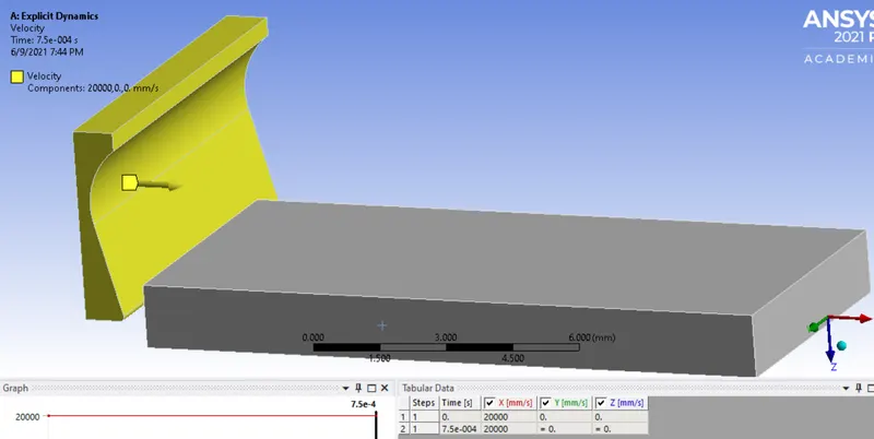
Enter the end time for the analysis. Go to Analysis settings and enter end time = 7.5e-4 s. Now insert the velocity for the cutting tools. Go to Explicit Dynamic > Insert > Velocity. Select the tool body. For X
component, enter magnitude of 20000 mm/s and for Y and Z component, enter magnitude =0 to avoid unnecessary motion of tool.
And now finally insert a fixed support to fix the workpiece. Go to Explicit Dynamic > Insert > Fixed support and fix the workpiece.
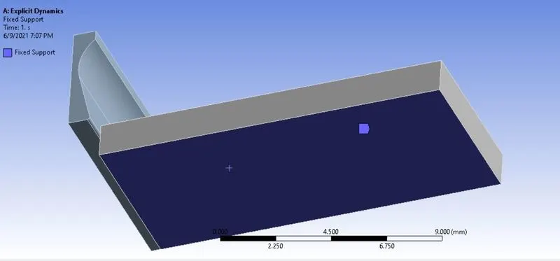
The case set up is now completed. List the required results and run the simulation.
- Results:
Stress contour for the model:
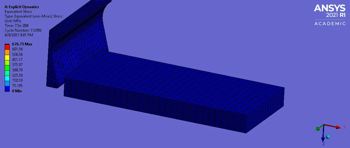
Max stress of 676.75 Mpa is observed in the workpiece.
Total Deformation in the model:
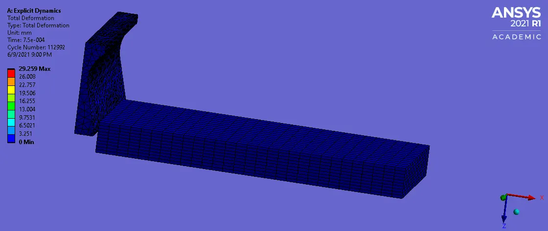
Max deformation of 29.59 mm is observed in the model.
Temperature in the component:
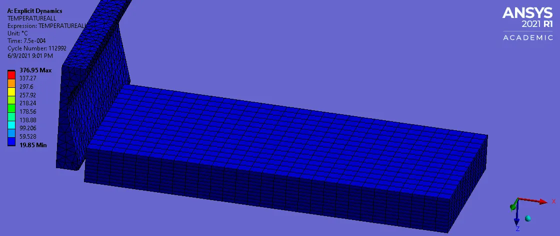
Max temperature of 376.95 °C is observed in the workpiece.
Results: Case 2 - Tool velocity of 15000 mm/sec:
Stress contour in the model:
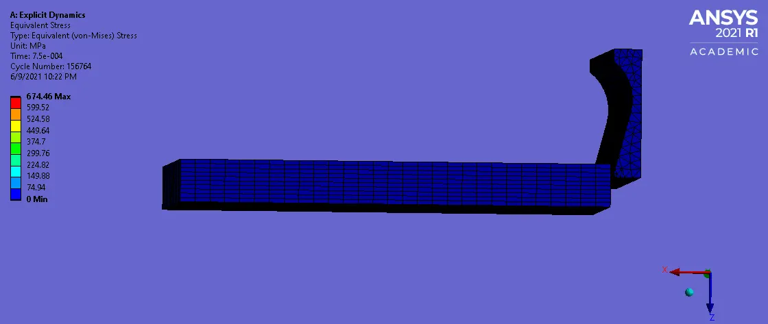
Max stress of 674.46 Mpa is observed in the model.
Total Deformation:
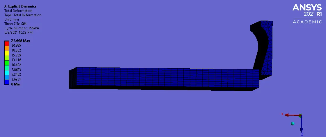
Max deformation of 23.60 mm is observed in the model.
Temperature in the model:
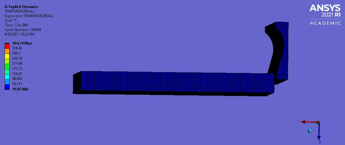
Max temperature of 364.74 °C is recorded on the workpiece.

The stress is higher in the workpiece where the tool velocity is higher, because higher the tool velocity, greater will be the frictional forces between the workpiece and the cutting tool. Same is the case with the
deformation and temperature recorded. Higher tool velocity will lead to higher values of stress and temperature, whereas lower tool velocity will lead to lower stress and temperature in the workpiece.
- Conclusion: Thus, the give model is successfully simulated and the results are compared.