Week 12:Project 2-Meshing of Rear Wheel Holder challenge
Aim: To mesh the wheel holder of the car and it should follow the parameter as shown below, and also assigning a thickness to it.
Target Element Length = 5 Units
|
S.N |
Quality Criteria |
Value |
|
1 |
Aspect Ratio |
5 |
|
2 |
Skewness |
45 |
|
3 |
Warping |
15 |
|
4 |
Taper |
0.5 |
|
5 |
Min. Length |
2 Units |
|
6 |
Max. Length |
8 Units |
|
7 |
Min angle Quad |
45 |
|
8 |
Max angle Quad |
135 |
|
9 |
Min angle Tria |
20 |
|
10 |
Max angle Tria |
120 |
|
10 |
Tria % |
10 |
Instruction to be followed:
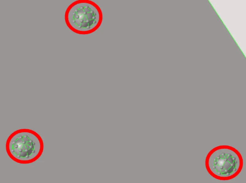
- Remove the buttons which are shown below because it will be difficult to capture that area as well mesh flow will not be proper. Except this feature, all the other features should be captured with proper element quality
Model:
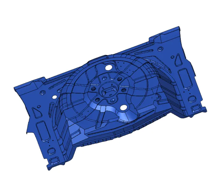
SPARE WHEEL WELL
A spare wheel well, also called spare Wheel baffle, is a recessed storage tub located in the trunk of the vehicle, as name suggest it houses the spare wheel and tyre, along with lug wrench and wheel jack. Traditionally it was made of stamped steel, however this part play an important role in the vehicle’s rear structure and crash safety and it is also prone to corrosion due to fact that its underside is always exposed to road elements, Now days manufacture using lighter material from aluminium to composite material at present, reducing both way in terms of weight and cost
Why we do Geometrical cleanup?
While we importing any geometry data it generally come up with little errors, some geometrical issues are
Surfaces are not stitched together.ie. (there, is a gap present between the surfaces)
Very small surfaces are squeezed between the surfaces.
Sometimes duplicate surfaces are present
The junction between the two surfaces also contains the gaps, overlaps and misalignments.
In order to remove that issues and errors we do geometry cleanup.
In geometry cleanup we doing Topology repair and following some strategies:
- Understanding the size and scale of the model
- Set up a cleanup tolerance based upon the previously determined global element size
- Use topology display tool to determine that what need to be fixed and check out for the free edges inside the geometry
- Find the duplicate surfaces and delete them
- Use the equivalence edges to join the free edges as many as possible
- Use toggle to combine any remaining free edges also make sure about the tolerance
- Use filler surface to filling any missing surfaces
- Use the suppressed option to suppress the function of the particular line
During meshing we have to take care about
- Feature should be capture properly
- No back to back trias
- There should be element connectivity between the elements
- No opposite trias
- No rotational quads
- Quality check to ensure that all element are within good quality
Note: During meshing make sure to check for free edge option at regular interval. It will help us to show that where there is element connectivity in the mesh or not
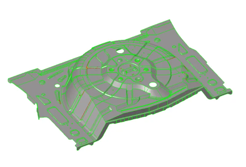
Model:
Procedure:
- Import the geometry in Hyper-mesh by using import option, make sure to check that which type of file you have, so during importing option you have to select the files type such as .iges, Solid-works, .stp file format for importing the file.
- Now next step is to clean the geometry, we have to remove all the geometrical errors from the model
- Now to check any errors and determine what need to be fixed, so to display the topology of the 2D geometry go to 2D topo option in tool bar.
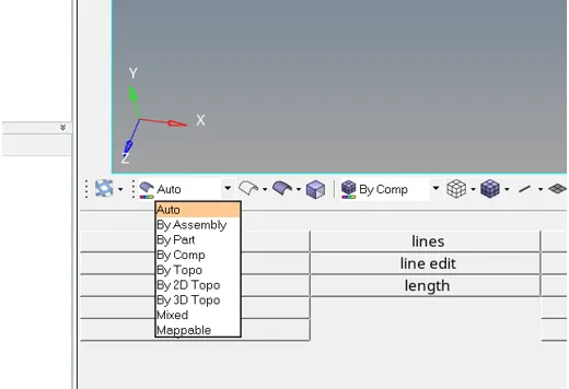
- So, by this 2D topo option we can easily visualize the geometry and we able to find out what need to be fixed in the geometry.
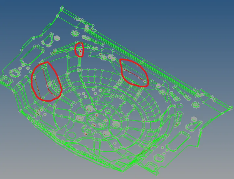
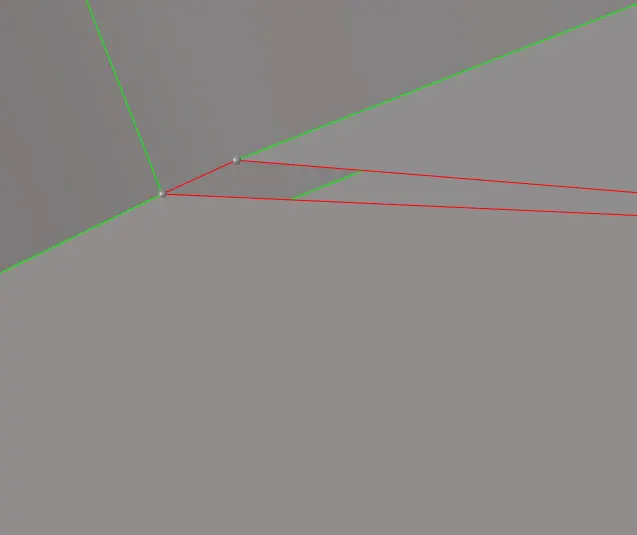
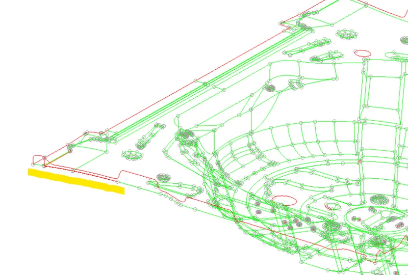
Here surfaces are not stiches properly
For stich the surface, we can use Replace point option to paste the point with other point
- After stich the surface, now we have to remove the small buttons from the geometry as mentioned above in the instructions
Now we can delete these buttons by using delete option and also, we can fill the remaining surface by using filler surface option in quick edit panel.
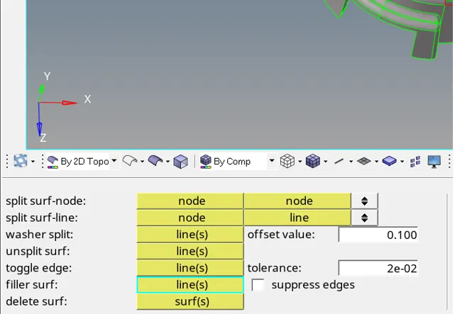
Filler surface option to fill the missing surface
- We can use all the option for doing geometrical clean-up as mentioned above and also, we can use the auto clean-up option to clean the geometry, we can also set the clean-up parameter while doing auto-clean-up.
- After completing the geometrical clean-up and removing all the errors from the geometry, now we can extract a mid-surface from the geometry, we can extracted mid-surface either manually or either by using auto-mid surface option in geometric panel, for manual mid-surfacing we use offset option to offset the surfaces to the middle
- Here we having sheet-metal component, so it is clear that it having unform thickness, so we can use the auto mid-surface option to extracting the mid-surface from the geometry, if we have component whose thickness is vary just like plastic component, we can adopt manual mid-surface option for extracting a mid-surface.
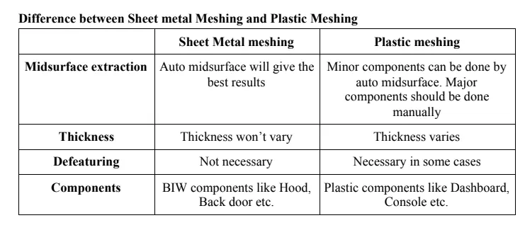
Image source: Skill Lync
Tool require to extract mid-surface for the plastic component / manual-mid-surfacing
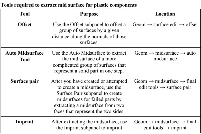
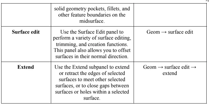
By these options we can extract the mid-surface manually or either we can use the auto mid-surface option to extracting the mid-surface
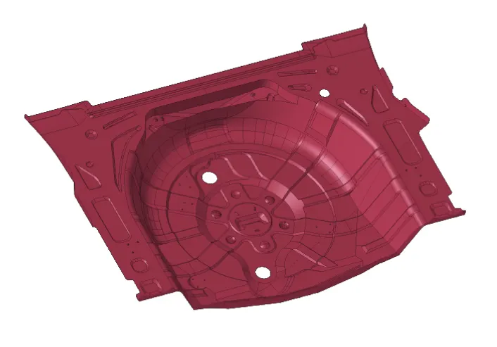
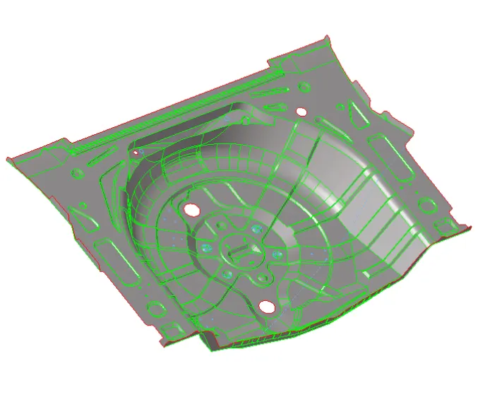
Mid-surface of component is extracted
- After extracting a mid-surface, now we have to check for either geometrical errors is present in model or not, if present we have to remove it by the option as mentioned above
- Now after we remove all the geometrical errors or we can say after cleaning the mid-surface properly, now we can start the mesh, but before mesh we have to set quality parameter as mentioned above
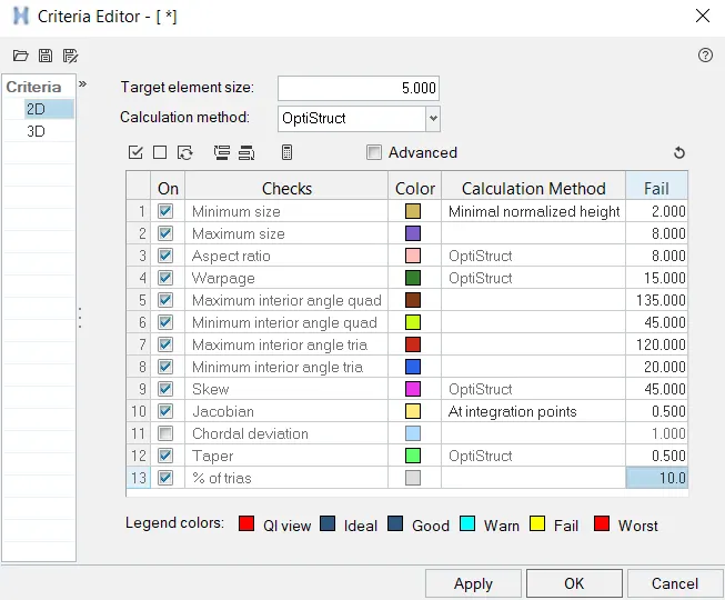
Setting a Quality-Parameter
- After setting a quality parameter, now we can start the mesh with Target element size of 5 , we try to mesh the small-small parts of the com[ponent for getting better accuracy and better handling on mesh
- Before meshing or during meshing make sure to check the symmetry of the component, if symmetry is present then we don’t have to mesh that region we simply mesh one side and reflect that mesh on other side
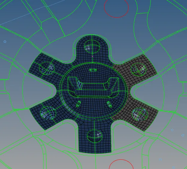
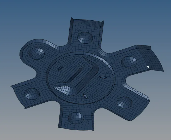
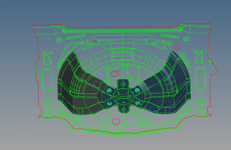
Reflecting the mesh
- After reflecting the mesh make sure to check the element connectivity, for that go to Tool > edges > Preview equivalence > equivalence for connect the mesh, But some time due to large gap it can’t connect the elements, so we have to manually connect the element by pasting the node with other node
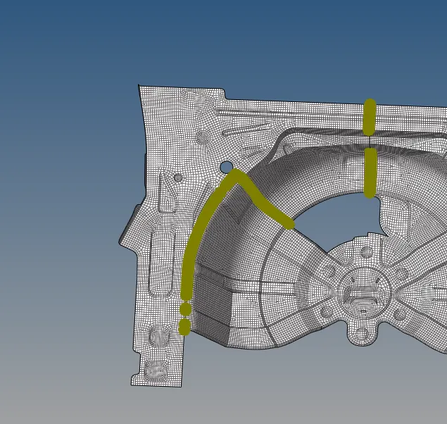
- Also to check element connectivity we can go for free edge option in Tool panel, if inside the mesh there is red colour line it means it is a free edge, free edge means element is not connected properly, so we have to connect the element, also we have to check for element connectivity for regular interval of time.
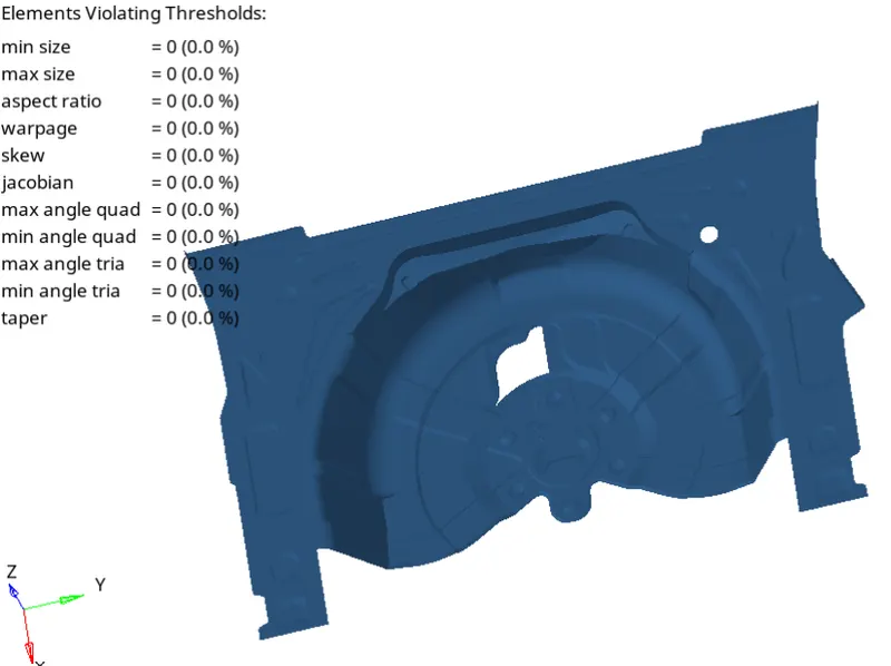
Element quality index of half model
- Now in similar way we have to mesh the other portion of the model, also make sure to check the symmetry in the model, it will save your lot of time
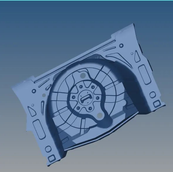
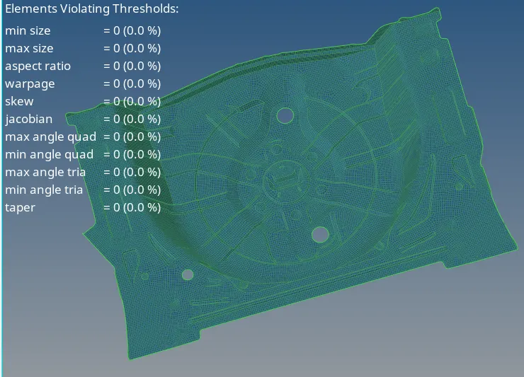
Element quality index for complete model
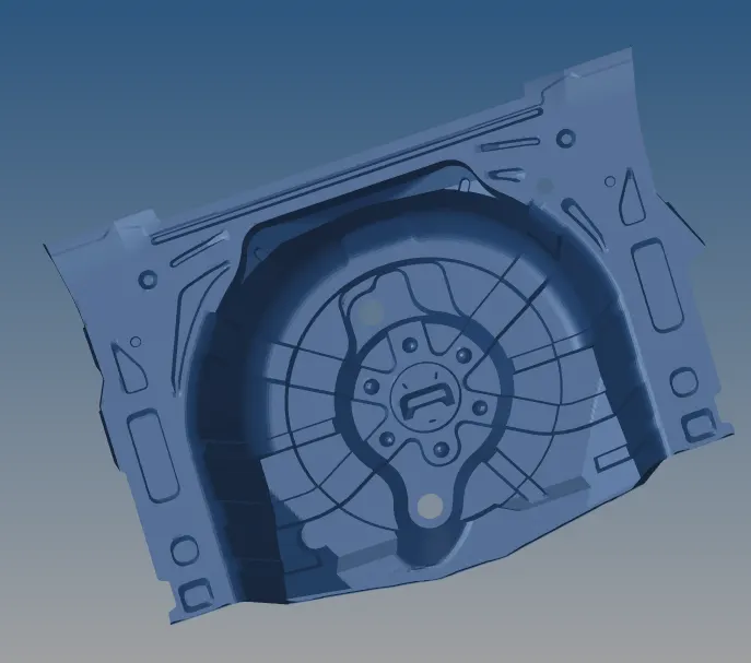
Final meshed model
- After meshing the overall component, now we have to assign thickness to it, for that we have to create a property and assign a material and thickness to property, then we have to assign a property to that component.
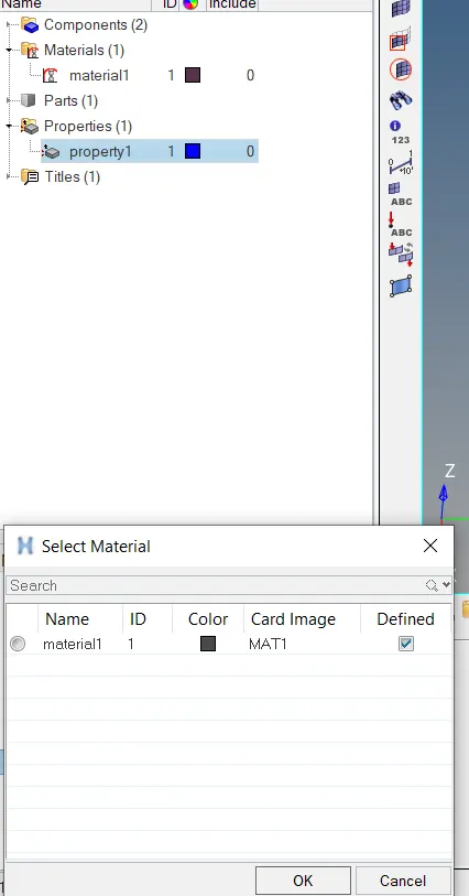
Assigning a material and thickness to the property
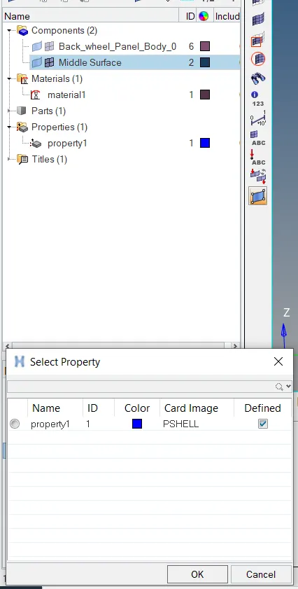
Here we assigning a property to the component
- To check whether thickness is assigned to component or not, go to 2D detailed representation option to check the thickness, if we have a component that having different thickness, then we have to move that varying thickness parts into different component collector and we have to create different property to it and assigning a thickness to it.
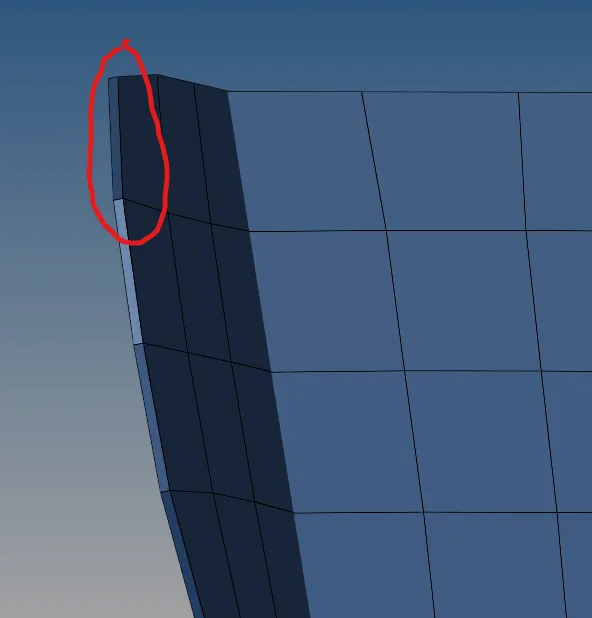
Thickness is assigned to the component
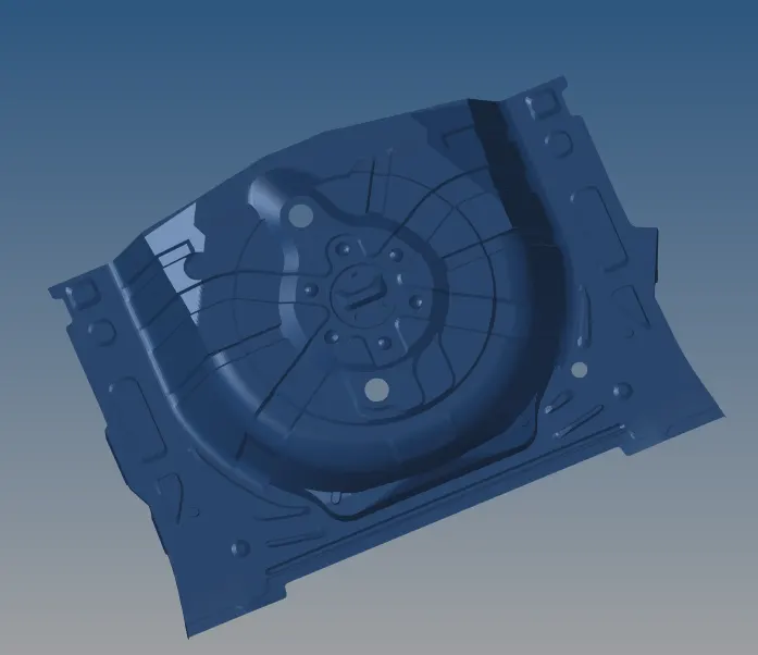
Final Model
Learning outcomes:
- Understanding about the manual geometrical clean-up options
- Understanding about how to handle trias in critical regions
- Understanding about different method to remove the errors from the mesh
- Understanding about the geometry capturing in critical regions