Deploying Connectors in Frame Assembly using HYPERMESH
INTRODUCTION
FEM or finite element method is all about discretizing any object into small-sized elements, and then apply physics onto those elements to see the effect that occurs on the integrated elements. This is the basis of any finite element analysis technique. The direction of the force and its magnitude, the dof, the moment, the torque, etc. have to be defined to see the occurrence.
But, before applying physics, the most important point to note is that in FEM node connectivity is very important. If in case, there is no node connectivity, the result would not converge to any solution. Mathematically, it means that the equations are not clearly defined. If the model imported in the pre-processor is an assembly, in such a case, maintain the node connection is very difficult, and also it is not recommended. The model has to be represented as close as possible to the real-time scenario.
Practically, any assembly is joined with various kinds of attachments. It includes bolt joint, seam weld, spot weld, etc. To give similar kinds of connections in FEM, there are tools available in Hypermesh. Those are called connectors. In this work, a frame assembly is meshed with 2d elements and then connected with 1d connectors. It includes seam weld connectors, spot weld connectors, bolt joint connectors, adhesives, and spring elements.
- Aim
To connect the frame assembly model using various types of 1d connectors available in Hypermesh.
- Objective
- To mesh the various parts of the frame assembly using 2d elements.
- To connect all the parts of frame assembly using 1d connectors of Hypermesh.
PROCEDURE
- Meshing
The model imported in Hypermesh included the mid-surfaces of the parts of the frame assembly, as shown in fig. 1.
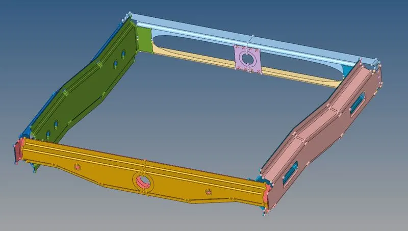
Figure 1: Mid-surfaces of the parts of the frame assembly.
For attaching the parts using connectors, it is important to mesh the parts, at first. Thus the next stage was to mesh those mid-surfaces. All the parts were meshed with a 2d element size of 5 mm, as shown in fig. 2.
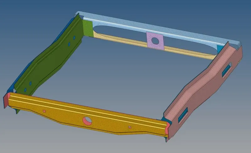
Figure 2: Meshed frame assembly, with 2d element size of 5 mm.
- Connectors
For each kind of joints available in the real-world, individual elements are made available in the pre-processors. Moreover, some companies have developed their own theory, and accordingly the elements. For attaching the parts of the frame assembly, some criterion was provided using which the connections had to be made. The criterion is as shown below:
- Right-Rail_2 & Front-Truss_1: Seam-Quad (angled+capped+L).
- Left-Rail_2 & Front-Truss_1: Quad elements.
- Front-Truss_2, Front-Truss_1 & Right-Rail_1: Spot weldwith 3 Layers and 5 mm Diameter.
- Front-Truss_2, Front-Truss_1 & Left-Rail_1: Hexa (Adhesive).
- Rear-Truss_2 & Right-Rail_2: Bolt Connector.
- Rear-Truss_2 & Left-Rail_2: Bolt Connector.
- Right-Rail_1 & Right-Rail_2: Spot-weld with Rigid Elements.
- Left-Rail_1 & Left-Rail_2: Spot-weld withSpring Elements.
- Rest all the components left to join them with suitable connectors.
To deploy Seam-Quad (angled+capped+L) elements, it is available in 1D → connectors → seam. In that, the node list needs to be selected as a location to place seam quad elements. The ‘connect what’ is the option to select the component which has to be attached. Under the ‘type’ option, Seam-Quad (angled+capped+L) has to be selected as a seam element. The ‘tolerance’ is the search tolerance or the search radius in which the nearby nodes have to be searched. Weld angle is generally kept 45º. The cap angle is the angle between the normals of the two elements at the corner. It is kept at 75º. The runoff angle is the angle between normals of two-seam elements lying on the same line. It is kept at 10º. After selecting all the options, and hit create, the seam weld elements create as shown in fig. 3.
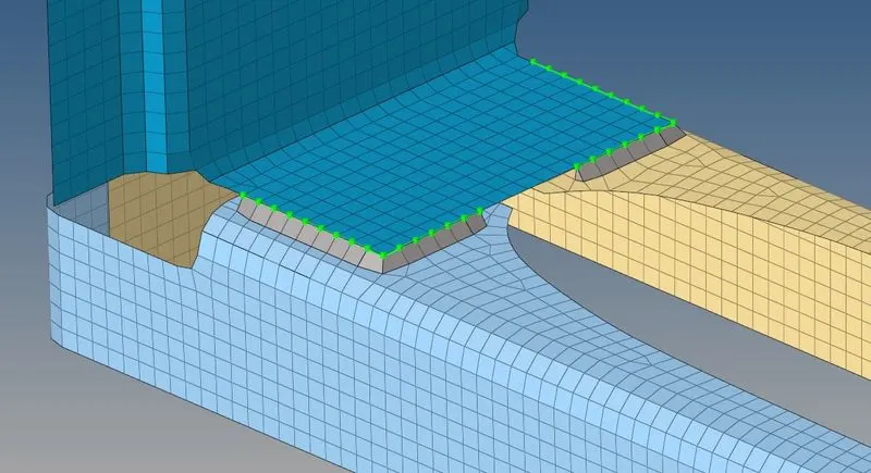
Figure 3: Seam-Quad (angled+capped+L) elements connecting the Right-Rail_2, Front-Truss_1, and Front-Truss_2.
Deploying seam connection with quad elements to attach two parts is as same as deploying the Seam-Quad (angled+capped+L) elements, as discussed before. The only difference is to select the ‘type’ as quads. Fig. 4 shows the seam weld connection with quad elements.
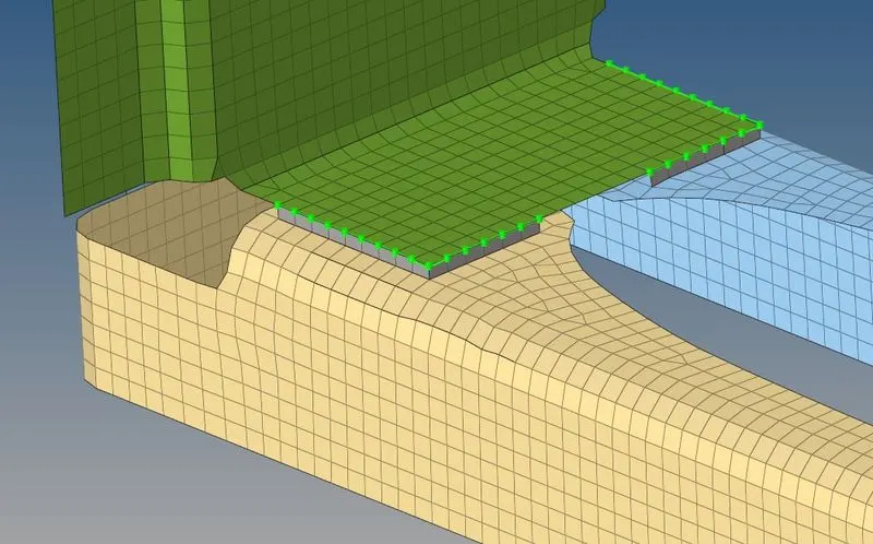
Figure 3: Seam connection with quad elements.
To connect parts with spot weld, 1D → connectors → spot is the path. In that, the node list was selected as the location to place the spot weld elements. The ‘connect what’ was selected as the components which need to be attached. The ‘type’ is selected as a weld. The ‘num layers’, which means the number of layers, was selected as the ‘total 3’, and the diameter was given 5. After hitting create, the spot weld connection looks like as shown in fig. 4. The Front-Truss_1, the Front-Truss_2, and the Right-Rail_1 are attached using spot weld elements.
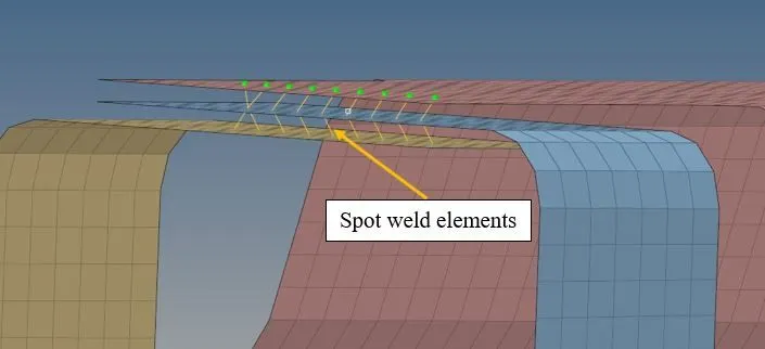
Figure 4: The Front-Truss_1, the Front-Truss_2, and the Right-Rail_1 are attached using 1d spot weld elements.
To connect two parts with Hexa (adhesive) element, again the procedure is the same as discussed for connecting two parts with Seam-Quad (angled+capped+L) elements. The only difference is that the ‘type’ has to be selected as Hexa (adhesive). Fig. 5 shows the parts attached with Hexa (adhesive) elements.
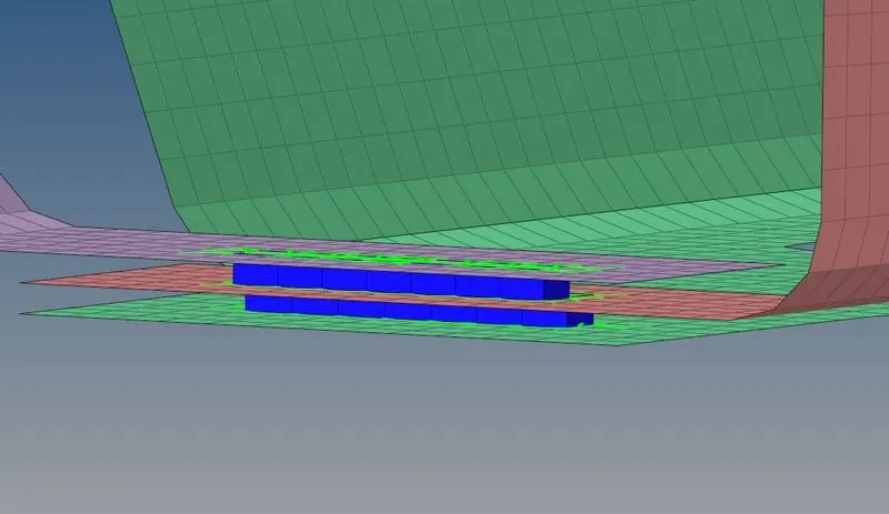
Figure 5: 3 parts viz. the Front-Truss_1, the Front-Truss_2, and the Left-Rail_1 attached with Hexa (adhesive) elements.
Bolt joint is the most common and most significant kind of connection. It is used for the easy mantle and dismantles of assembly. In FEM, bolt connection is considered as rigid joint unless the focus of the study is on the bolted connection only. For making the connection as bolted joint, 1D → connectors → bolt is the path. In that, nodes were selected where the bolted connection was required. The ‘connect what’ was selected as components that have to be attached. The ‘tolerance’ was given as 10. The type was selected bolt (general). The number of layers was defined as a 'total 2'. Additionally, the option was selected as the ‘create hole, if none’, because the hole was not present, and it had to be created.
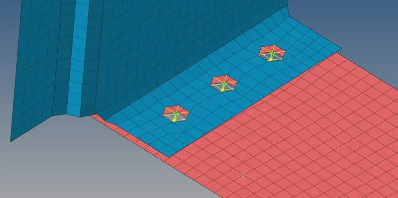
Figure 6: The Right-Rail_2, and the Rear-Truss_2 connected with 1d bolt elements.
To create the spot weld connection with any specific kind of elements, 1D → connectors → spot is the path. In that, everything had to be selected as selected while deploying the Seam-Quad (angled+capped+L) elements. Here, for connecting the Right-Rail_1 and the Right-Rail_2, the type was selected as rigid, and for connecting the Left-Rail_1 and the Left-Rail_2, the type was selected as spring.
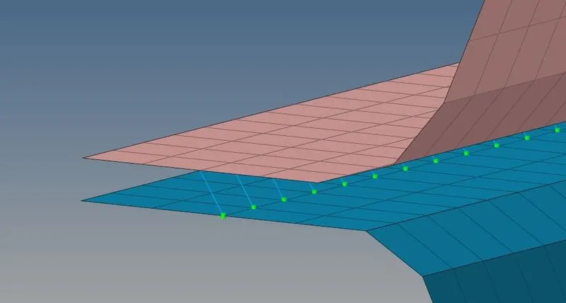
Figure 7: The Right-Rail_1 and the Right-Rail_2 connected with spot weld rigid elements.
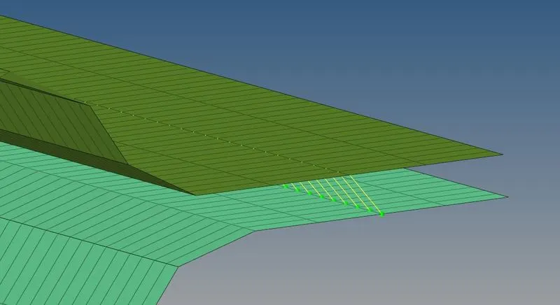
Figure 8: The Left-Rail_1 and the Left-Rail_2 connected with spot weld spring elements.
Even after making all these connections, some connections were still remaining. All those remaining connections were made using spot weld with rigid elements. Fig 8. shows the picture of the assembly with all the connections.
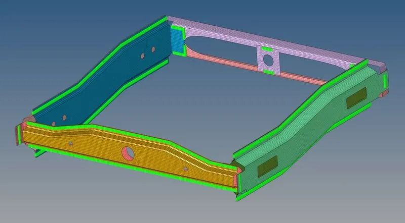
Figure 9: 3-d point converted to ‘spotweld’ connection entity.
CONCLUSION
CAE or computer-aided engineering on any model requires good observation and knowledge about the kind of manufacturing used to connect parts. In this work, the frame assembly is connected using various 1d elements. There are several options available for the element to choose to represent any specific kind of connection. Some of those elements are learned in this work.