Week 9-Creation of 1D Connectors Challenge
AIM:
Mesh the given Component with a Mesh size of 5mm.Create connector and Attach the various parts of the given model.
METHODOLOGY:
Methodology to perform Meshing the given Component with a Mesh size of 5mm.
Create connector and Attach the various parts of the given model
- IMPORT MODEL
- DELETE SOLIDS
- GEOMETRY CLEANUP
- MESHING
- CREATING CONNECTOR
PROCEDURE:
- IMPORT MODEL:
- Import the given model into hypermesh.
- Importing model may not be possible if the file format is not supported by the hypermesh.
2.DELETING SOLIDS:
- Before generating 2D mesh for the components then the solids should be deleted.
- It can be done by using the delete tool and select solids and select all to delete all solids from the component.
3.GEOMETRY CLEANUP:
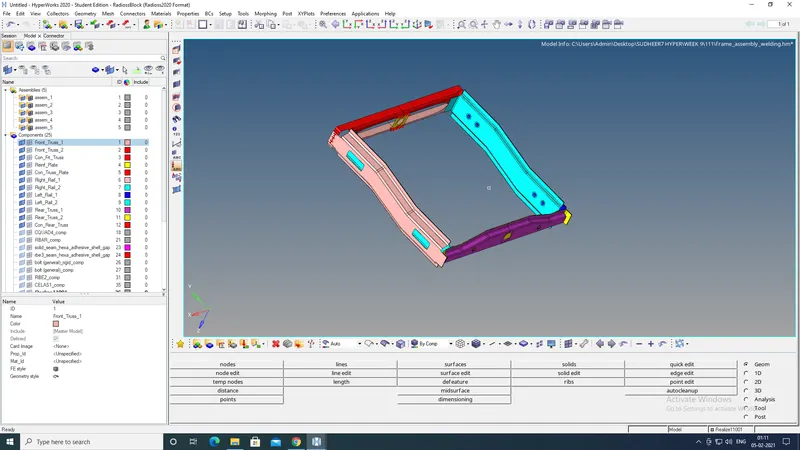
- After importing the model the main process is geometry cleanup.
- In some cases if the model is imported to hypermesh due to some graphical issues the geometry changes may occur, So geometric cleanup plays an important role.
- Remove all unnecessary lines from the model.
- Check if any surface is missing or overlapped.If any surface is missing, create a new surface over there by using a surface tool or filler surf tool.
- If two surfaces are not stretched together then use a toggle edge tool to stretch together.
- By using the toggle edge tool the feature lines can be suppressed for the better mesh generation.
4.MESHING THE COMPONENT:
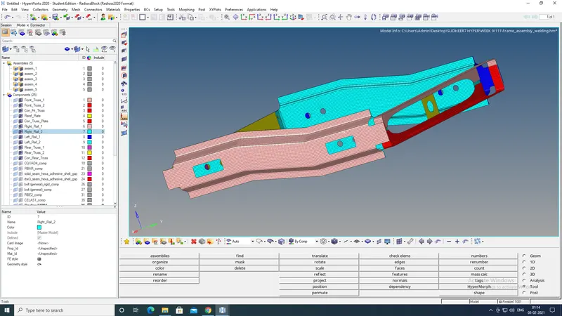
- For the given housing model to perform the meshing select 2D.
- In 2D by using AUTOMESH tool mesh is generated.
- Before meshing, always assign the quality criteria.
- Select the whole surface to generate quads mesh and proceed with the meshing.
- After meshing, check the failure elements and solve the failure elements by using cleanup tools.
- After creating connectors between the components the meshflow may change.
- So after creating the connector check the mesh flow.
5.CREATING CONNECTOR :
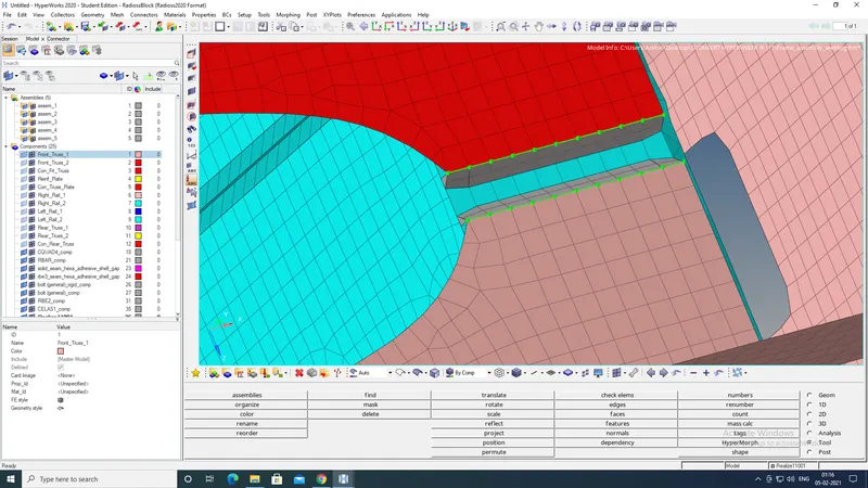
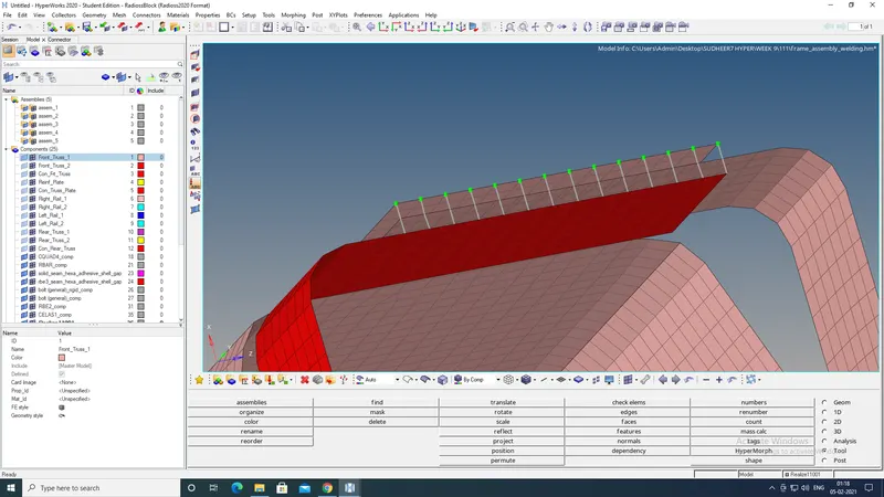
- Right_Rail_2 & Front_truss_1:- Seam-Quad(angled+capped+L).
- Select seam from connectors in 2D.
- From seam select Seam-Quad(angled+capped+L).
- Select the nodes where seam weld should be required and switch on the retain nodes.
- Select the components.
- Mention spacing and tolerance value.
- The spacing value is equal to the element size and tolerance is the distance between two components.
- Input weld angle, cap angle and runoff angle as required.
- Click on the create button, to create seam weld.
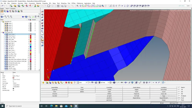
- Left_Rail_2 & Front_truss_1:- Quad elements.
- Select seam from connectors in 2D.
- From seam select Quad.
- Select the nodes where quad should be required.
- Select the components.
- Mention spacing and tolerance value.
- Click on the create button, to create quads between components.
- Front_truss_2, Front_truss_1 & Right_Rail_1:- Spot weld with 3 Layers and 5mm diameter.
- Select spot from connectors in 2D.
- Select weld tool from spot.
- Select the nodes for creating spot weld.
- Select the components.
- Input the tolerance value for realising the connector.
- Click on create, to create spot weld between components.
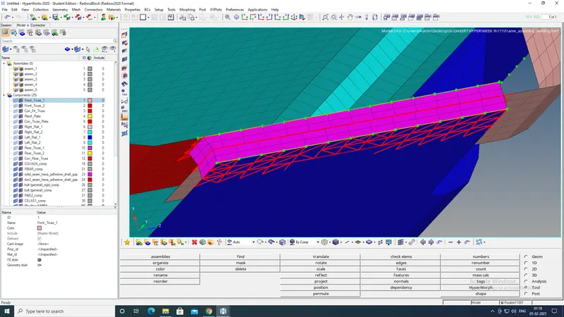
- Front_truss_2, Front_truss_1 & Left_Rail_1:- Hexa (Adhesive).
- Select seam from connectors in 2D.
- From seam select Hexa (Adhesive).
- Select the nodes where Hexa (Adhesive) should be required and switch on the retain nodes.
- Select the components.
- Mention spacing and tolerance value.
- The spacing value is equal to the element size and tolerance is the distance between two components.
- Input STRIPS, CODES and width value of adhesive to create.
- Click on the create button, to create Hexa (Adhesive).
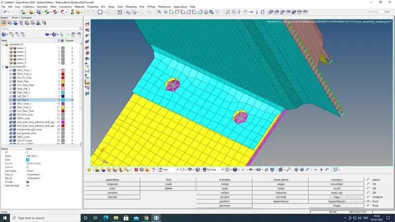
- Rear_truss_2 & Right_Rail_2:- Bolt Connector and Rear_truss_2 & Left_Rail_2:- Bolt Connector.
- Select bold connector.
- Select the centre node where bold is to be created.
- Select the components .
- Select numbers of layers to be weld and mention the value.
- Input tolerance value.
- Click the create button, to create bolts on components.
- Right_Rail_1 & Right_Rail_2:- Spot-weld with Rigid Elements and Left_Rail_1 & Left_Rail_2:- Spot-weld with Spring Elements.
- Select spot from connectors in 2D.
- Select rigid tool from spot for spot weld with rigid elements.
- Select spring tool from spot for spot weld with spring elements
- Select the nodes for creating spot weld with rigid elements.
- Select the components.
- Select the remesh option instead of adjust realization in mesh dependent.
- Input the tolerance value for realising the connector.
- Click on create, to create spot weld with rigid elements between components.
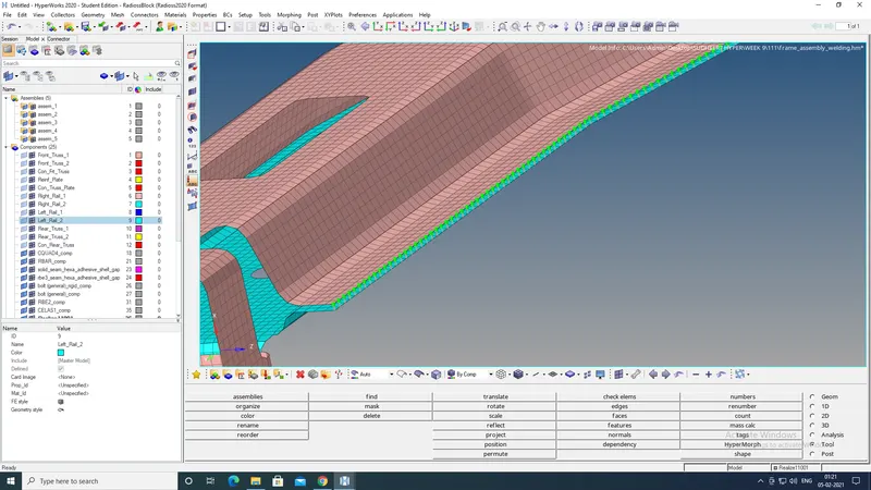
SPOT WELD WITH RIGID ELEMENTS
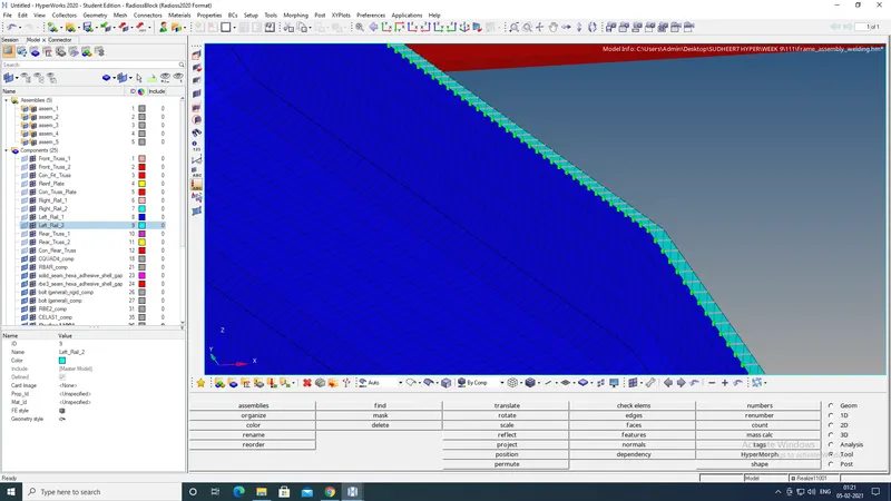
SPOT WELD WITH SPRING ELEMENTS
LEARNING OUTCOMES:
- Meshing.
- Creating suitable connectors between the components.
RESULT:
Meshed the given Component with a Mesh size of 5mm, And created connector and Attached the various parts of the given model successfully.