Week 4- Challenge
AIM:
Create 1D elements on the following component with given cross-section and DOF.
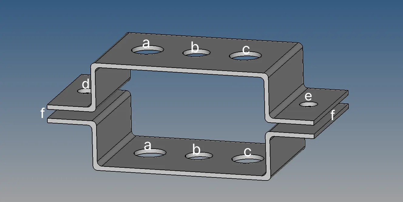
- Rod element:- with only translational DOF and RBE2 link
Cross-Section: BOX- Dimension a= 12 mm
dimension b=10 mm
Thickness t= 0.75 mm
- Beam element:- with all DOF and RBE3 link
Cross-Section: I Section- Dimension a= 8 mm
Dimension b= 10 mm
Dimension c= 8.5 mm
Thickness t1= 0.75 mm
Thickness t2= .6 mm
Thickness t3= .6 mm
- Bar element:- with only x and y DOFs With RBE3 link
Cross-section: CROSS section- Dimension DIM1= 5 mm
Thickness DIM2= 1.2 mm
Dimension DIM3= 10 mm
Thickness DIM4= 1.2mm
- & e. apply the mass of magnitude 10 with RBE2 link
- Join the two components with Spring elements
METHODOLOGY:
METHODOLOGY TO CREATE 1D ELEMENTS ON THE COMPONENT WITH GIVEN CROSS-SECTION AND DOF.
- IMPORT MODEL
- GEOMETRY CLEANUP
- DELETING SOLIDS
- GENERATING MIDSURFACE
- MESHING
- CREATING ELEMENTS
- APPLYING THE MASS
- CREATING SPRING ELEMENTS
PROCEDURE:
Creating the elements on components involves the following procedure
- IMPORT MODEL:
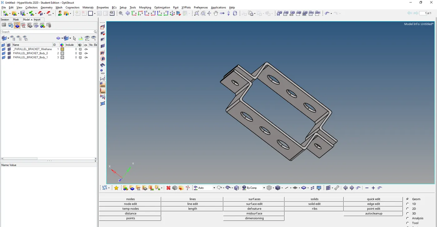
- Import the given model into hypermesh.
- Importing model may not be possible if the file format is not supported by the hypermesh.
- GEOMETRY CLEANUP:
- After importing the model the main process is geometry cleanup.
- In some cases if the model is imported to hypermesh due to some graphical issues the geometry changes may occur, So geometric cleanup plays an important role.
- Remove all unnecessary lines from the model.
- If more geometric cleanup is required then by using autocleanup maximum geometric errors can be solved.
3.DELETING SOLIDS:
- Before generating 2D mesh for the components then the solids should be deleted.
- It can be done by using the delete tool and select solids and select all to delete all solids from the component.
4.GENERATING MIDSURFACE:
- For generating the midsurface the solids should be removed.
- Create washer splits near the holes for better mesh flow.
- For the given component,have 2 parts generate midsurface individually.
- By using the midsurface tool midsurface can be generated manually and by using auto midsurface it can be done fastly.
- By using a midsurface tool select surfaces and generate midsurface.
5.MESHING:
- Meshing for the component can be done by using the Automesh tool.
- By giving the quality criteria for the meshing and selecting the whole midsurface to generate meshing.
- Mostly by using the automesh tool the complete surface will be meshed and for proper and uniform mesh some modification should be done.
- By using 2D meshing tools mesh can be edited or can be rebuilt.
6.CREATING ELEMENTS:
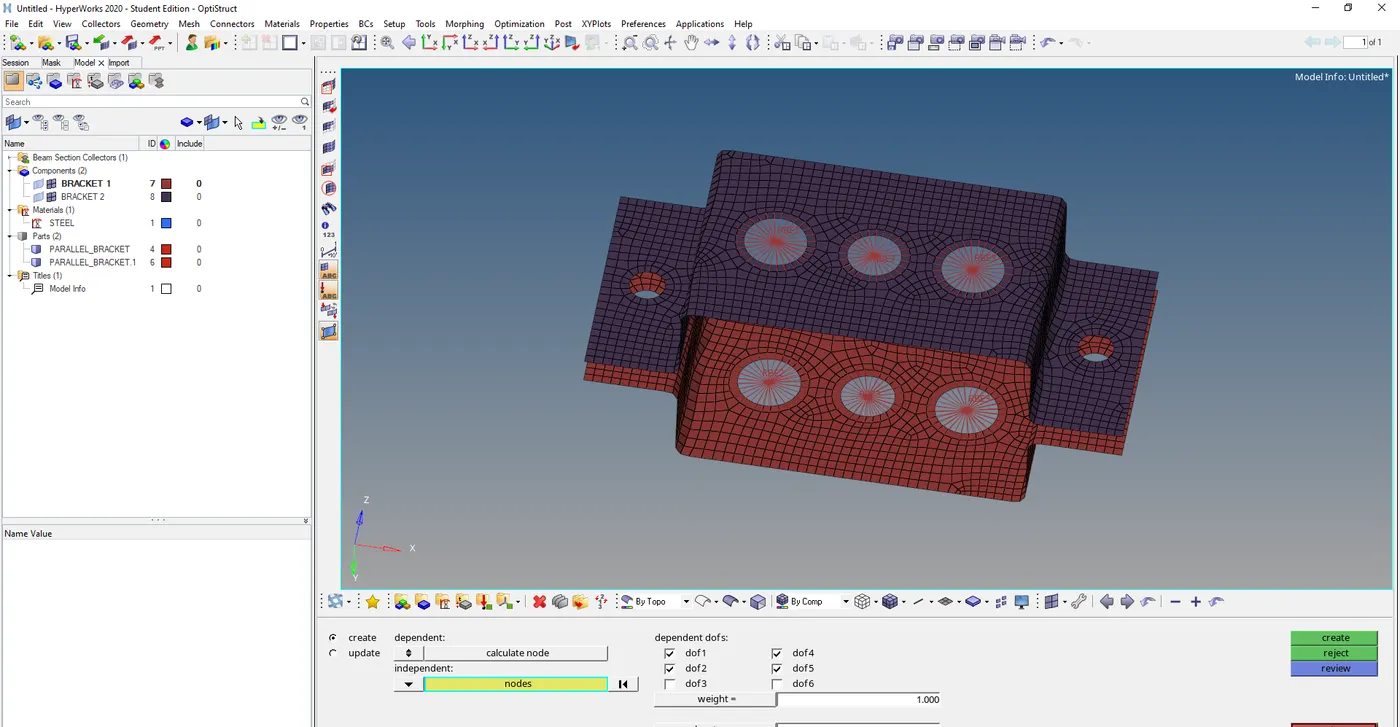
- For creating the elements by the given cross section and DOF meshing should be done.
- According to the given data, using 1D tools creates RIGIDS at two surfaces at point “a”.
- Create rbe3 elements at points “b” &”c”.
- Create rbe2 elements at points “d” & “e”.
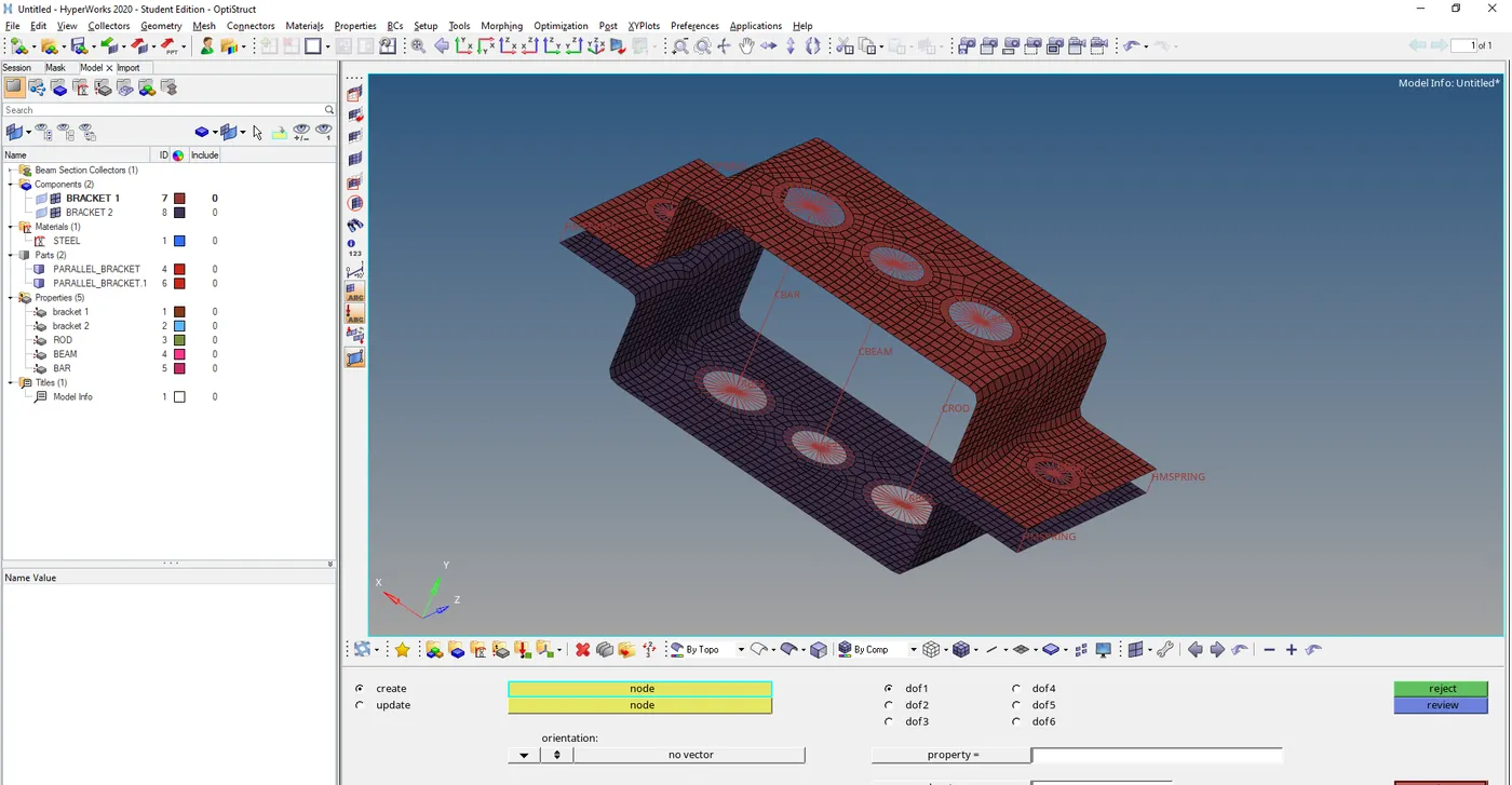
- By using HyperBeam tools from 1D construct three elements: they are rod, bar and beam with a given cross section.
- Create new properties for the following:
a.bracket 1
b.bracket 2
c.ROD
d.BEAM
e.BAR
- Assign all the metal for the bracket1 and 2.
- And also assign all the hyper beam elements for the rigids at the desired positions.
- For viewing the 1D elements completely use tool 1D Detailed Element Representation.
- By using the tool mentioned above the 1D elements can be seen with their complete cross section.
7.APPLYING THE MASS:
- For knowing any result masses must be applied on the component.
- Here in this component according to the given data the mass should apply on point “d” & ”e”.
- For applying mass at the given point use masses tool from 1D.
- Apply the mass with the given magnitude.
8.CREATING SPRING ELEMENTS:
- The spring elements should create at the corners of the components.
- By using the spring element join the two components at the four corners.
- By using springs tool under 1D, the springs can be created.
- The complete model is done with the required cross section and DOF.
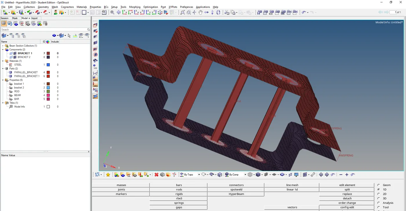
LEARNING OUTCOMES:
- Creating the new components by using the Geometry tools.
- Geometry cleanup.
- Generating mesh by using 2D mesh tools.
- Creating the 1D elements with required conditions
- Assigning the properties for the HYPER BEAMS.
RESULT:
Created 1D elements on the following component with given cross-section and DOF successfully.