Week 9-Creation of 1D Connectors Challenge
OBJECTIVES
The objective of this assignment is to mesh the given model following the quality criteria mentioned below and create different types of connection between the components as mentioned below.
The quality criteria that should be followed is
| SL no | Quality criteria | value |
| 1 | Aspect ratio | 5 |
| 2 | Skewness | 45 |
| 3 | Warping | 15 |
| 4 | Taper | 0.5 |
| 5 | Min length | 2 |
| 6 | Max length | 8 |
| 7 | Min angle quad | 45 |
| 8 | Max angle quad | 135 |
| 9 | Min angle tria | 30 |
| 10 | Max angle tria | 110 |
| 11 | Tria percentage | 15 |
The different types of connections that should be made is mentioned below.
- Right Rail 2 & Front truss 1 - Seam-Quad(angled+capped+L)
- Left Rail 2 & Front truss I - Quad elements
- front truss 2, Front truss 1 & Right Rail 1 - Spot weld with 2 Layers and 5 mm Diameter
- Front truss 2, Front truss 1& Left Rail I - Hexa (Adhesive)
- Rear truss 2 & Right Rail 2 - Bolt Connector
- Rear truss 2 & Left Rail 2 - Bolt Connector
- Right Rail 1 & Right Rail 2 - Spot-weld with Rigid Elements
- Left Rail 1 & Left Rail 2 - Spot-weld with Spring Elements
- Rest all the component left should be connected with appropriate connectors.
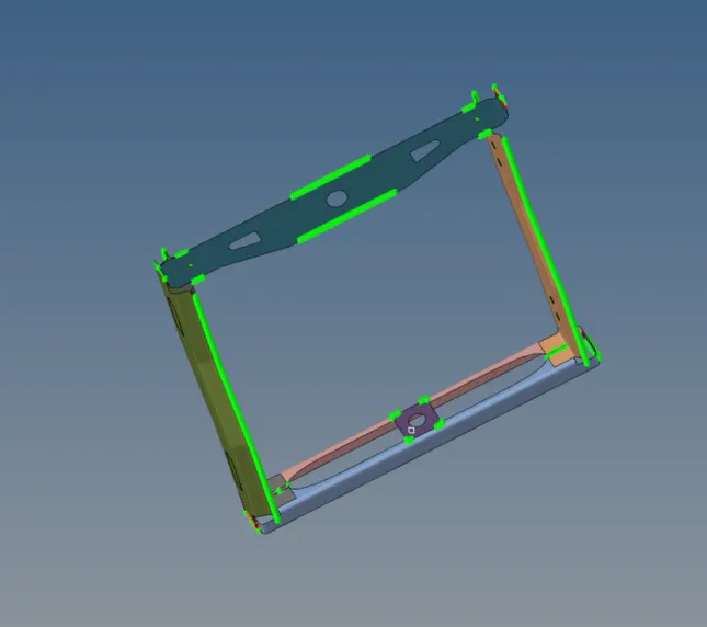
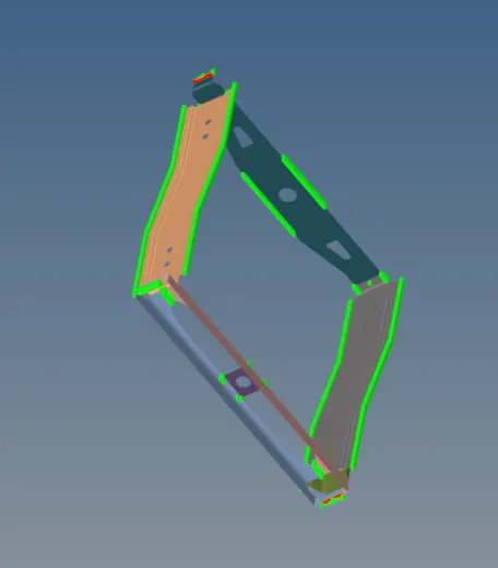
The cad model image of the component is shown below.
PROCEDURE
The model is first imoprted and all the components are meshed with the target element size of 5.
Case 1
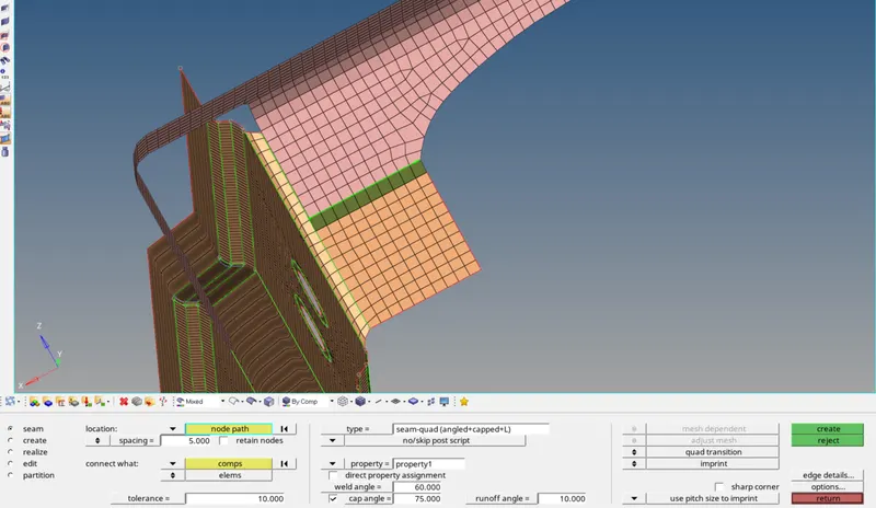
The connection between right rail 2 and front truss 1 should be a seam-quad (angled+capped+L) type connection. This connection is made by selecting the 'connectors' option in 1D panel followed by selecting the type of connection to be 'seam'.
From the seam panel we select a nodepath where we need the seam to be , then the components on which the seam should be realized is selected. The 'spacing' should be our target element size. Then we select the type of seam we need and create it. In this case after realizing the connection the mesh adjacent to the seam needed to be slightly remeshed. The figure below shows the seam connection realized as well as the seam connector panel.
Case 2
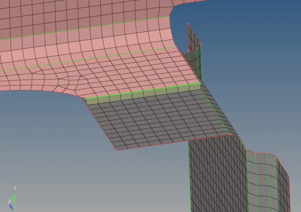
The connection between Left Rail 2 & Front truss I should be a seam quad connection. This is also made by utilizing the seam option in 'connectors' panel as earlier . Here the type of connection is 'quad'.The figure below shows the seam connection realized.
Case 3
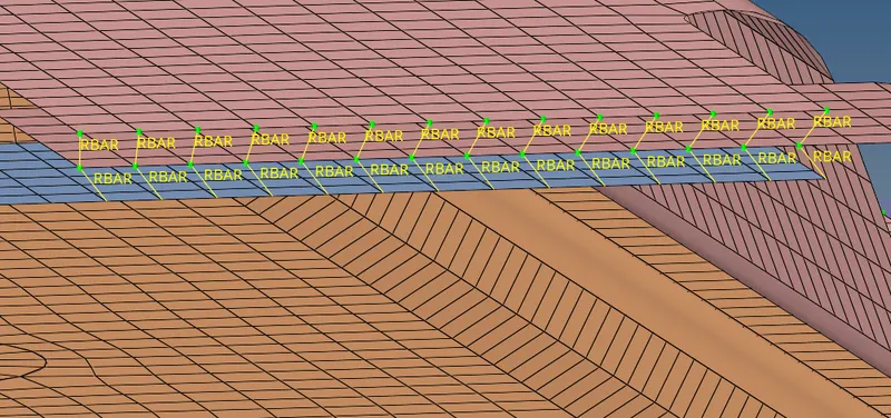
The connection between front truss 2, Front truss 1 & Right Rail 1 should be a spot weld with 5 mm diameter. This connection is made by utilizing the 'spot' option present in the 'connectors' panel. The type of spot connection is selected as weld in the spot panel. The figure below shows the spotweld connection realized.
Case 4
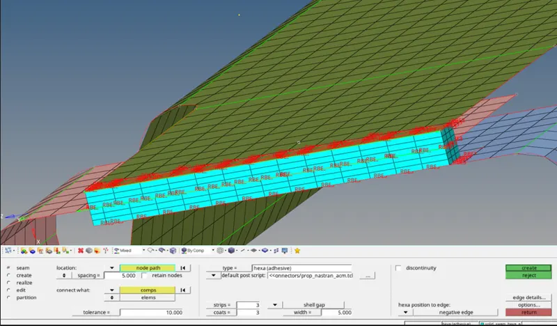
The connection between Front truss 2, Front truss 1& Left Rail 1 should be a hexa (adhesive) connection. This connection is made by utilizing the 'seam' option present in the 'connectors' panel.The type of seam connection is selected as hexa (adhesive) in the seam panel as shown below.
Case 5
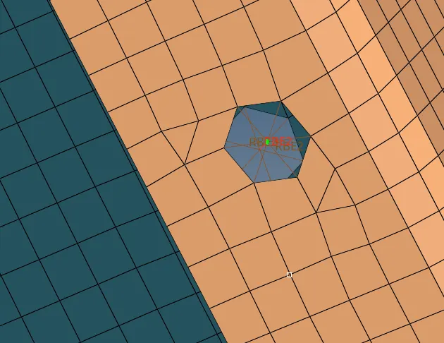
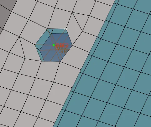
The connection between rear truss 2 & right Rail 2 should be a bolt connection. This connection is realized by selecting the bolt option in the connector panel. Figure below shows the realized bolt connection. The bolt connection may cause distortion in the mesh which should be corrected accordingly.
Case 6
The connection between Rear truss 2 & Left Rail 2 should be a bolt connection. This connection is realized by selecting the bolt option in the connector panel. Figure below shows the realized bolt connection. The bolt connection may cause distortion in the mesh which should be corrected accordingly.
Case 7
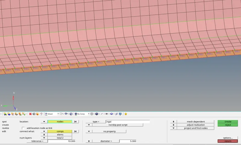
The connection between Right Rail 1 & Right Rail 2 should be a spot-weld with rigid elements. This connection is made by utilizing the 'spot' option present in the 'connectors' panel. The type of spot connection is selected as 'rigid' from the spot panel.The figure below shows the spot connection realized.
Case 8
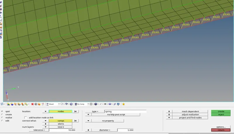
The connection between Left Rail 1 & Left Rail 2 should be a spot-weld with spring elements. This connection is made by utilizing the 'spot' option present in the 'connectors' panel. The type of spot connection is selected as 'spring' from the spot panel.
Rest of the components are connected using the same types of connections as mentioned above.
RESULT
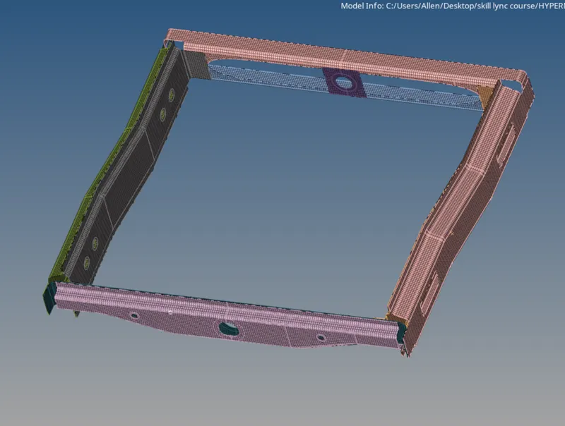
All the connections mentioned in the objectives are realized. The final image of the model with all the connections is shown below.