Week - 5 - Modelling Spotwelds
AIM
In this project we are going to simulate a collision of a crashbox with a rigidwall. Here, the crashbox contains two parts and are connected by spotwelds modelled either by beam elements or solid elements. The aim of this project is to study the difference between the two methords used to model spotwelds namely, the beam type and the solid type.
EXPLANATION
A spotweld is a connection that can be used to join two parts especially sheet metals. However, in LS DYNA there are different methords of modelling a spotweld. We can either use beam elements or solid elements to model spotweld .Here we try to understand the difference between two approaches by modelling them seperately . Here we create spotwelds between two shell surface and subject them to a crash test in which the crashbox hits the rigidwall at 50 kmhr.Then we identify the different forces acting on the spotwelds and try to analyze it.
CASE SETUP
The file containing the two shell surfaces was the initial input of this assignment . After opening the keyword in LS Prepost the project was given a suitable title.First we try to setup the basic keywords necessary for both solid and beam spotweld methords.
The crashbox needs to crash into a rigidwall so a rigidwall is created using the keyword *RIGIDWALL_PLANAR.The rigidwall was given a suitable id and title so as to identify it . The NSID is set to zero as all the nodes in this case are slave to the rigidwall .For defining the rigidwall we need coordinates of the head and tail of a vector normal to the rigidwall. The coordinates of the tail of the normal vector is set as (-14,-150,-100) and the head as (0,-150,-100).
The units was set to gm-mm-ms using *CONTROL_UNITS keyword.Now we try to create the spotwelds between the two shell surfaces. Firstly, we will set up the spotwelds containing beam elements and run the simulation then we will move onto solid spotwelds.
In order for us to create beam elements for spotwelds, we need two nodes for a spotweld. In this project we create six spotwelds placed symmetrically about its centre.For easy identification of nodes that make a beam element ,we renumber the nodes that becomes a part of the beam element as 10,20,30..etc on the upper shell and the nodes on the lower shell as 100,200,300 etc..Now we create the beam elements by using the element generation option on the mesh menu.
For giving the crashbox an initial velocity of 50kmphr or 13.89 mm/ms *INITIAL_VELOCITY card was used and the initial velocity was given to a nodeset consisting of all the nodes of the crashbox.
*CONTACT_AUTOMATIC_SINGLE_SURFACE keyword used to prevent the shells from self penetration. MSTYP card was set to zero and slaveset type was set as part set and SSID was assigned a partset containing both the shell elements.
The material for the shell elements were created using *MAT_ELASTIC and steel is used as the material with RO=0.00785, E=2e+5 ,PR=0.32 and MID=1. *MAT_SPOTWELD was used to define material model for spotweld. Steel was used as the material with RO=0.00785, E=2e+5, SIGY=250, TFAIL=3, NRR=5000,NRS=5000.
{The failure time of the spotweld was established by first running the simulation with a very high value of failure time .After the simulation, from the results it was found that the maximum forces in spotweld occours at about 2 milliseconds. So, for the final simulation failure time of 3ms was chosen}
Next we define a section for the beam elements. This is done by utilizing the keyword *SECTION_BEAM. An element formulation (ELFORM) of 9 was used. Also, cst=1 with thickness TS1=TS2=3mm. The shell section was defined using *SECTION_SHELL with ELFORM=16 and T1=T2=T3=T4=1.5mm.
Different parts are now assigned using the keyword *PART. The shell elements were given sections of shell and elastic material defined earlier, while beam element parts were given the spotweld material and beam sections defined earlier.
*CONTACT_TIED_SHELL_EDGE_TO_SURFACE was used to define the contacts between the beam elements and the shells. Masterset was a partset containing the shell elements while slaveset was a partset containing all beam elements.
The termination time was set to 6ms by *CONTROL_TERMINATION. Also,for obtaining cross sectional forces generated in the middle of the crashbox a cross section plane is created using *DATABASE_SECTION_PLANE keyword along the length of the crashboxes and PSID is set to zero as all parts are included.
*DATABASE_HISTORY_NODE was used to trace the acceleration of a node in the middle of the crashbox (along its length).
Also, ASCII options like GLSTAT,NODOUT,RCFORC,SECFORC,SLEOUT,SWFORC with DT=1ms using the keyword *DATABASE_ASCII_option.
*DATABASE_BINARY_D3PLOT was also activated with DT=1ms to obtain the simulation result. After, these steps are completed the file is saved and run in LS-RUN application to get the simulation results.
A similar methord is used for the simulation of spotwelds using solid elements. Here the solid elements are generated again by using the element generation tool from the mesh options, the difference being that the solid option is selected instead of beam option from the element generation pop-up menu. All other parameters are similar to the beam element case, the only difference is when we define the section. The section is generated using the keyword *SECTION_SOLID with ELFORM=1. After setup the file is saved and run in LS-RUN application to obtain the simulation results.
RESULTS
1. Beam element case
Since we have given a weld fail time of 3ms the weld fails at 3ms while maximum forces we generated at about 2 milli seconds when the structure hits the wall and reaction forces generate. The axial forces and the shear forces generated in the spotweld is given below for all the six spotwelds.
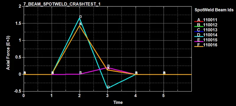
Axial forces generated in the spotwelds are shown above .The maximum value of axial force obtained is 1660 units.
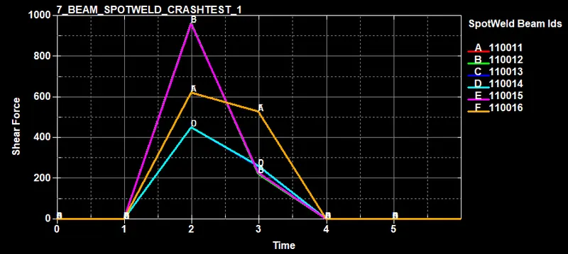
The shear forces generated in the spotwelds are shown above. The maximum value of shear force obtained is 966 units.
The plots of all energies which include kinectic energies ,internal energy, total energy and sliding energy is given below .
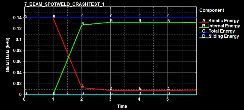
It is oserved that the kinectic energy drops as a result of crash while the internal energy goes up while the total energy remains constant.
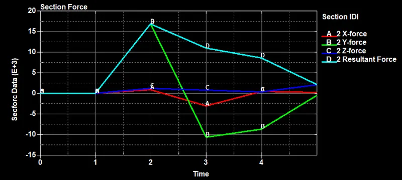
The cross sectional forces generated in the middle of the crashbox along its length is given below.
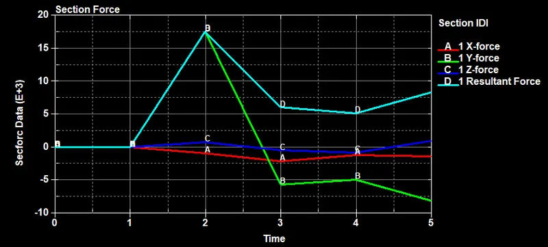
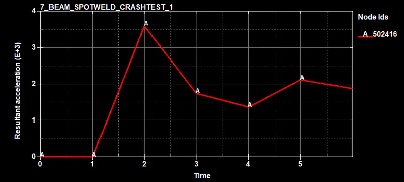
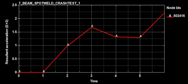
The acceleration plot of a node 502416 in the middle of the crashbox is given below.
The maximum stesses and strain that occour in the system are given below.
max x strain = 5e-01 max y strain = 5e-01 max z strain = 5e-01
min x strain = -1.824e-03 min y strain = -1.036e-03 min z strain = -5.103e-04
max x stress =8.425e+02 max y stress = 5.008e+02 max z stress = 4.78e+02
min x stress = -3.401e+02 min y stress = -1.939e+02 min z stress = -9.553e+01
2. solid element case
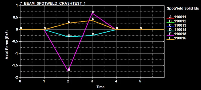
The axial forces and the shear forces generated in the spotweld is given below for all the six spotwelds.
Axial forces generated in the spotwelds are shown below .The maximum value of axial force obtained is 1720 units.
The shear forces generated in the spotwelds are shown below. The maximum value of shear force obtained is 1240 units.
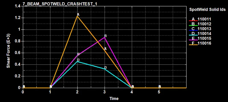
It is observed that the solid spotwelds are more stiff and can take more axial and shear forces.
The plots of all energies which include kinectic energies ,internal energy, total energy and sliding energy is given below .
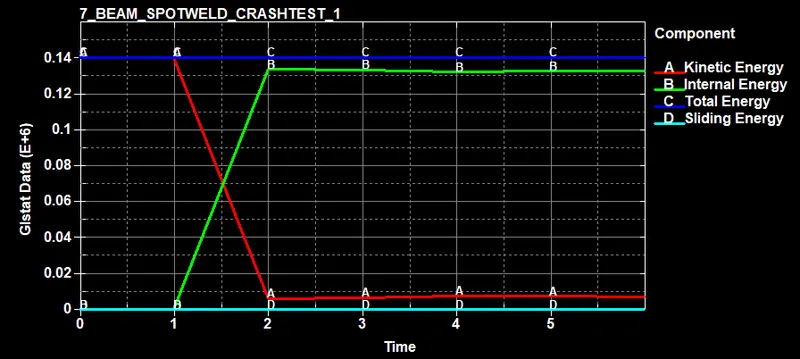
It is oserved that the kinectic energy drops as a result of crash while the internal energy goes up while the total energy remains constant.
The acceleration plot of a node 502416 in the middle of the crashbox is given below.
The cross sectional forces generated in the middle of the crashbox along its length is given below.
The maximum stesses and strain that occour in the system are given below.
max x strain = 5e-01 max y strain = 5e-01 max z strain = 5e-01
min x strain = -1.767e-03 min y strain = -8.363e-01 min z strain = -9.825e-01
max x stress =3.974e+02 max y stress = 4.319e+02 max z stress =3.924e+02
min x stress = -3.082e+02 min y stress = -1.927e+02 min z stress = -1.134e+02
CONCLUSION
It is observed that the solid spotwelds are more stiffer and hence can take more axial and shear forces than the beam spotwelds. This may be the reason that the acceleration of the node along the middle of the crashbox is lower for solid spotweld as it has resisted more displacement.