Week - 3 Drop test Challenge
AIM
The objective of this experiment is to try to create the different essential cards or input decks needed for the simulation of a cellphone dropped from a particular height onto a rigid wall. Another main objective is to try to get a hands on experience of using the different pre and post processsing tools in LS DYNA so as to get a clear understanding of how the software works.
EXPLANATION
CASE SETUP
In this experiment a cellphone and a rigid wall file that is meshed is taken.
The first thing to do is to load the given keyword file onto LS DYNA.This can be done by selecting open and then selecting LS DYNA keyword file from the file menu and the selecting the appropriate keyword file.
After the file is loaded select model and part from the toolbar and then select the *TITLE keyword. This keyword is used for giving an appropriate title for the project. My project was titled CELL_PHONE_DROP_TEST. Then we click accept and then done.
Next thing is to rename the different parts for easy understanding and for this step we select the keyword *PART_PART.The cellphone was named CELLPHONE and the shell wall was named RIGID_SHELL_WALL and the solid behind the wall was named SOLID_BEHIND_SHELL.
Next a nodeset containing all the nodes of the cellphone was created using the create entity option so that the nodeset can be used when defining the *INITIAL_VELOCITY card. Then the *INITIAL_VELOCITY card was used to give the cell phone an initial velocity of -10m/s. -ve sign is indicating that the cellphone is travelling in -z direction.
The *CONTROL_UNITS card was selected and the length was set to meters , time in seconds, mass in kilogram.
Then the wall that cellphone hits was constrained by using *BOUNDARY_SPC-SET card. For this a nodeset containing all the nodes of the wall was created.
Then the sections of the cellphone, the solid behind the shell wall and the shell wall was defined using the keywords *SECTION_SOLID and *SECTION_SHELL. Element formulation of 1 was used when defining section of solid .The element formulation used for shell was 2 and was given a thickness of 1mm.
Two types of material models were defined one was *MAT_RIGID for the shell wall and the solid behind the shell wall and the density was set to 2370kg/m^3 , Youngs modulus equal to 22.1Gpa and possions ratio of 0.15 .(these values are the values of concrete taken from R.C Hibbeler book). The other material model defined was *MAT_ELASTIC for the cellphone. The cellphone material was selected to be aluminium since most phones today are made of aluminium frames.The density was taken as 2790kg/m^3, youngs modulus =73.1Gpa and poissons ratio being 0.35. (These values were taken from R.C.Hibbeler).
Then the keyword *PART_PART was used to assign the appropriate material and sections to the different parts.
The contacts between rigid wall and cellphone was given by using *CONTACT_AUTOMATIC_SURFACE_TO_SURFACE. Here the MSTYP was given as 3( partid) and SSTYP was given as 3(partid) and the part given as the master was the rigid shell wall and the slave was cellphone since rigid wall does not deform while cellphone does.
The distance between the cellphone and the shell was found to be around 20m. So the phone should touch the wall at about 2 seconds since the velocity was given to be 10m/s. This time is calculated so as to know the approximate termination time for the simulation.For setting the termination time *CONTROL_TERMINATION was used and the termination time was set to 5s .
Then *DATABASE_BINARY_D3PLOT was used to get the result with DT=0.1. Also *DATABASE_ASCII option was activated and GLSTAT ,MATSUM, RCFORC was activated to obtain the various energies of models and materials and also the forces.
RESULT
The phone hit the ground at about a little over 2 seconds and the maximum von mises stress obtained was about 5 Mpa.
OBSERVATION
The cell phone was found to bend and the kinectic energy of the cellphone dropped drastically at around 2 seconds indicating that the cell phone has hit the ground (the graph of which is shown below)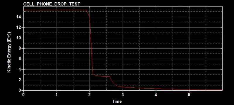 .
.
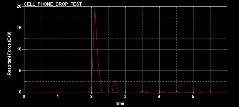
Also the resultant force increases at about 2seconds indicating that an impact has happened (the graph is shown below).
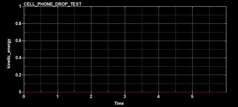
The kinectic energy of the rigid wall is constant indicating that the simulation is correct.
The animation of the simulation has also been attached.