Week - 4 - Crash Box Simulation
AIM
In this assignment we try to set up a basic crash test in which we will simulate a simple crash box hitting on a rigid wall at a particular velocity. The aim here is to understand the very basics of a crash test and analyse the data so as to understand how certain parameters (in this case the thickness of the material ) affects the system.
EXPLANATION
A crash box is a sophisticated highly energy absorbing structure that is used to reduce the impact and loads on the components nearby if a crash or damage occours.In this assignment we try to simulate a very basic crash box ,in this case a rectangular channel which can be thought of as a simple crash box. Here the crashbox is assumed to move with a consant velocity of 50kmph and crashes into a rigid wall faceon.Here we will be doing two crash simulation of which the first simulation will have a crashbox made of material of thickness 1.2mm and the other will have a thickness of 1.5mm.
CASE SETUP
The file containing the meshed crashbox was the inital input in this assignment.After opening the keyword in LS Prepost the project was given a title CRASHBOX_SIMULATION using the keyword *TITLE. Then the units was set to gm-mm-ms by using the *CONTROL_UNITS keyword.
For the crashbox to crash into a rigidwall a rigidwall needed to be created and was created using the keyword *RIGIDWALL_GEOMETRIC_FLAT .This keyword allows us to create a plane rigidwall very easily. The rigidwall was given an ID=1. The NSID is set to zero as all nodes in this case are slave to rigidwall. For defining the rigidwall we need the coordinates of the head and tail of a vector normal to the rigidwall.The coordinates of the tail of the normal vector is set as (-200,-110,-80)and the head as (100,-110,-80). Here I am defining a finite rigid wall so the coordinates of the head of a vector along the plane with tail same as that of the normal vector needs to be given. The head coordinates of the vector along the plane is given as (-200,0,-80). Also the length and width of the plane is also set to 400 and 200 using the cards LENL and LENM.
A contact between the rigidawall and crashbox is set using the keyword *CONTACT_AUTOMATIC_SURFACE_TO_SURFACE. The SSTYp is set as 3 and MSTYP as 3 and slaveset is the crashbox and the master set was given to be the rigidwall.
For giving the crashbox an intial velocity of 50kmph or 13.89mm/ms *INITIAL_VELOCITY card was used and the initial velocity was given to a nodeset consisting of all the nodes of the crashbox.
Now a section for the crashbox was defined using the keyword *SECTION_SHELL and the thickness was set to 1.2mm.Also the rigidwall was also given a shell section with thickness 1mm.
Then an elastic material model for crashbox was defined using the keyword *MAT_ELASTIC and the material given was steel with density 0.00785, youngs modulus=2e+05 , poissons ratio=0.32.
A material model for rigidwall was also given using the keyword *MAT_RIGID and the material given was concrete with density=0.00237, youngs modulus=2.9e+04,poissons ratio= 0.15.
Using the keyword *PART_PART appropriate sections and material ids was given to both crashbox and rigidwall.
The simulation endtime was set to 60ms by using the keyword *CONTROL_TERMINATION.
For getting the cross sectional force generated in the middle of the crashbox we use *DATABASE_CROSS_SECTION_PLANE and create a plane along the length of the crashbox.
*DATABASE_BINARY_D3PLOT was also activated with DT=1ms to obtain the simulation result.
Also ASCII options like GLSTAT, SLEOUT, RCFORC ,SECFORC was also activated with DT=1ms using the keyword *DATABASE_ASCII_option.
After this setup the keyword file is saved and run in ls run app to get the simulation and the results obtained are disscused below.
RESULT AND CONCLUSION
From the animation it is clear that the crashbox rebounces completely after hitting the rigidwall in both the cases (i.e at 1.2mm and 1.5mm thickness) .This may be since the velocity may be insufficient to cause the buckling of the crashbox. The animation of the final simulation is attached.
The plots of all Kinectic energies ,internal energy, total energy and sliding energy is given below for the thickness of 1.2mm. 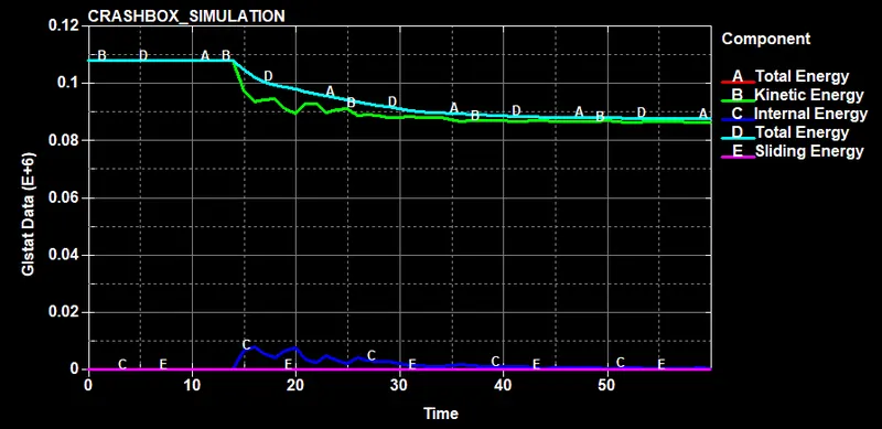
It can be seen from this plot that the kinectic energy decreases after hitting the wall and the rigidwall absorbs some amount of kinectic energy thereby decreasing the total energy. But total energy is a bit higher than the kinectic energy since the internal energy increases slightly in the crashbox due to the reaction forces acting on the rigid body. Sliding energy is zero since the contact happens for a very short duration and also since there is no sliding occouring.
The plot of all Kinectic energies ,internal energy, total energy and sliding energy is given below for the thickness of 1.5 mm.
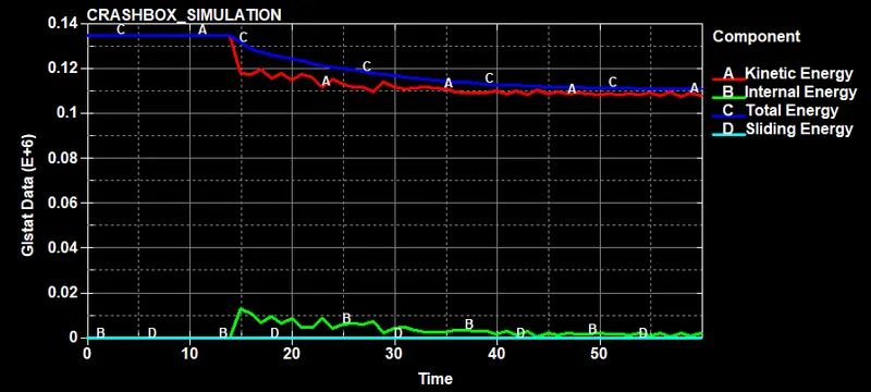
It can be seen from this plot that the kinectic energy decreases after hitting the wall and the rigidwall absorbs some amount of kinectic energy thereby decreasing the total energy. But total energy is a bit higher than the kinectic energy since the internal energy increases slightly in the crashbox due to the reaction forces acting on the rigid body. Sliding energy is zero since the contact happens for a very short duration and also since there is no sliding occouring.
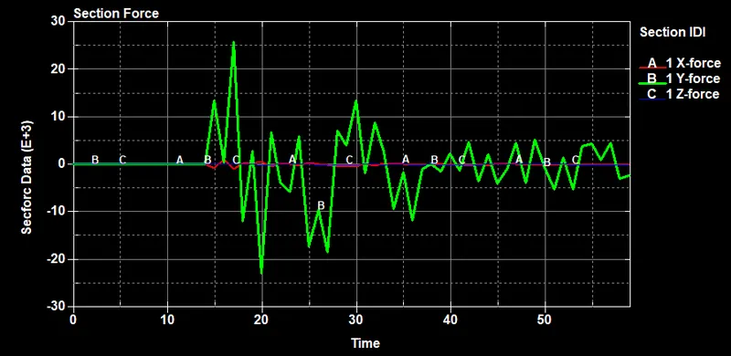
The plot of cross sectional forces generated along the middle of the crashbox is given below for 1.2mm.
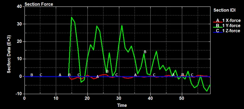
The plot of cross section forces generated along the middle of the crashbox is given below for 1.5mm.
The resultant acceleration plot of a node with node id 5094 along the middle of the crashbox is given below for 1.2mm case .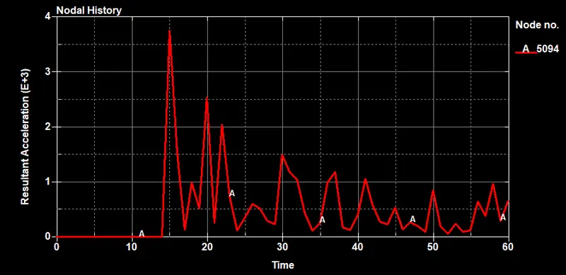
The resultant acceleration plot of a node with node id 5094 along the middle of the crashbox is given below for 1.5mm case .
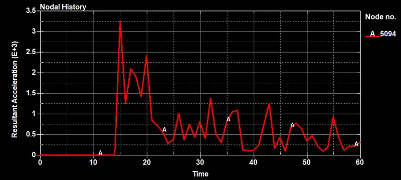
By comparing the acceleration plots of the same node 5094 from above it is clear that the resultant acceleration experienced by the node 5094 is less in the second case (when shell thickness is 1.5mm) as the displacement that may be induced in the node is less in the second case. This may be attributed to the fact that since the thickness of the shell is high more energy may be needed to cause the same displacement as in the first case (1.2mm case). Consequently we can infer from this result that the crashbox has become more sturdy when the thickness was increased.
The maximum directional stesses and strain along the length of the crashbox is noted below.
For 1.2mm case.
max x strain = 1.192e-03 max y strain = 5e-01 max z strain = 5e-01
min x strain = -1.331e-03 min y strain = -2.079e-03 min z strain = -2.004e-03
max x stress =2.487e+02 max y stress = 4.045e+02 max z stress = 4.112e+02
min x stress = -2.773e+02 min y stress = -1.19e+02 min z stress = -1.71e+02
For 1.5mm case
max x strain = 1.551e-03 max y strain = 5e-01 max z strain = 5 e-01
min x strain = -2.731e-03 min y strain = -1.797e-03 min z strain = -1.935e-03
max x stress = 4.22e+02 max y stress = 3.844e+02 max z stress = 3.364e+02
min x stress = -2.497e+02 min y stress = -1.1794e+02 min z stress = -1.783e+02
By comparing the maximum stress and strain values generated in the crashbox in both the cases we find that the thicker crashbox ( case 2 ) has more strain and stress values in the x direction when compared with the thinner crashbox . Also the thinner crashbox has more y and z stress and strain when compared with its own x strain and stress values which may mean that it is more likely to be deformed than the thicker crashbox as its x stress and strain values are higher when compared to its y and z stress and strain values.