Week 9-Creation of 1D Connectors Challenge
OBJECTIVE :-
mesh the given geometry. Provided below are the quality parameters that you have to follow.
Target Element size - 5 Units
|
S.N |
Quality Criteria |
Value |
|
1 |
Aspect Ratio |
5 |
|
2 |
Skewness |
45 |
|
3 |
Warping |
15 |
|
4 |
Taper |
0.5 |
|
5 |
Min. Length |
2 Units |
|
6 |
Max. Length |
8 Units |
|
7 |
Min angle Quad |
45 |
|
8 |
Max angle Quad |
135 |
|
9 |
Min angle Tria |
30 |
|
10 |
Max angle Tria |
110 |
|
10 |
Tria % |
15 |
Create connector and Attach the various parts of the given model
1. Right_Rail_2 & Front_truss_1:- Seam-Quad(angled+capped+L)
2. Left_Rail_2 & Front_truss_1:- Quad elements
3. Front_truss_2, Front_truss_1 & Right_Rail_1:- Spot weld with 2 Layers and 5 mm Diameter
4. Front_truss_2, Front_truss_1 & Left_Rail_1:- Hexa (Adhesive)
5. Rear_truss_2 & Right_Rail_2:- Bolt Connector
6. Rear_truss_2 & Left_Rail_2:- Bolt Connector
7. Right_Rail_1 & Right_Rail_2:- Spot-weld with Rigid Elements
8. Left_Rail_1 & Left_Rail_2:- Spot-weld with Spring Elements
9. Rest all the component left Join them with suitable connectors
THEORY :-
1. Connectors is an application in the Hypermesh which helps us to connect different non associated components. The establishment of connections are necessary as to provide the structural connections while application of load during simulation.
2. Hypermesh gives us wide range of variety of 2D connectors as per the industries and their applications
| SL. NO | Connectors | Definition & Application |
| 1. | SPOT | Use the Spot panel to create connectors that represent point connectors such as spot welds. These connectors can be realized as standard or custom weld representations. |
| 2. | BOLT | Use the Bolt panel to create connectors which will be represented as a 1D element construct. |
| 3. | SEAM | Use the Seam panel to create connectors that represent line connectors such as seam welds. These connectors can later be realized as standard or custom weld representations. |
| 4. | AREAS | Use the connector Area panel to create connectors that represent connections of larger regions, such as adhesives. These connectors can later be realized as standard or custom weld representations. |
| 5. | Apply MASS | Use the Apply Mass panel to create a dummy connector entity to add mass to a part, or create areas of mass to represent parts not present in the CAD or FE data. |
3. Apart from the above the there are few 1d ELEMENTS in the hypermesh based the application of loads
1. RBE2 :- REB2 transfer equal force in all direction ,
2. RBE3 :-REB3 transfer force according to distance that is the node which near to REB experience more force and vice versa.
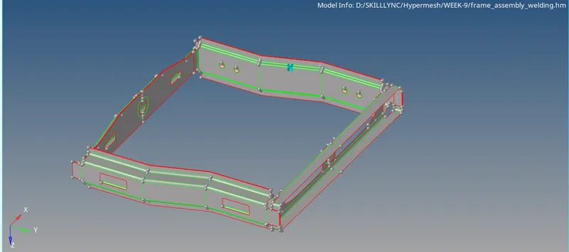
MODEL IMAGE
PROCEDURE
1. The the elements were first created on the the CAD model.
2. After that all the connection were establised on the different components.
3. Post completion of requisite from the objectives, the places where the necessary connection are required to be establised were then undertaken.
RESULTS
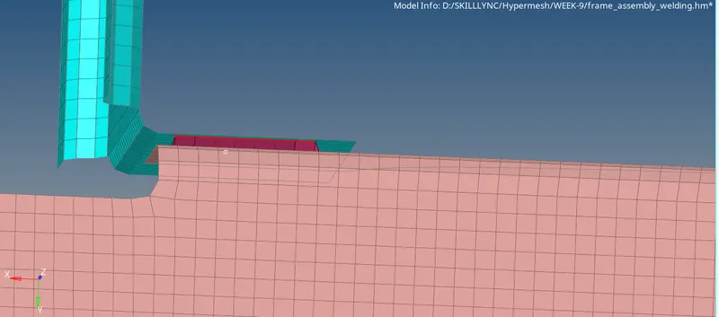
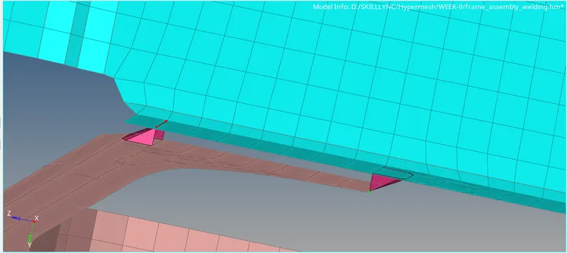
1. Right_Rail_2 & Front_truss_1:- Seam-Quad(angled+capped+L)
2. Left_Rail_2 & Front_truss_1:- Quad elements
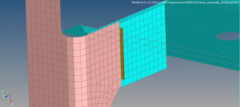
3. Front_truss_2, Front_truss_1 & Right_Rail_1:- Spot weld with 2 Layers and 5 mm Diameter
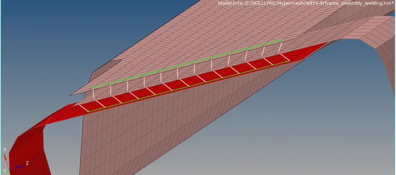
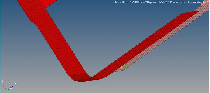
4. Front_truss_2, Front_truss_1 & Left_Rail_1:- Hexa (Adhesive)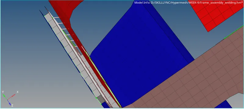
5. Rear_truss_2 & Right_Rail_2:- Bolt Connector
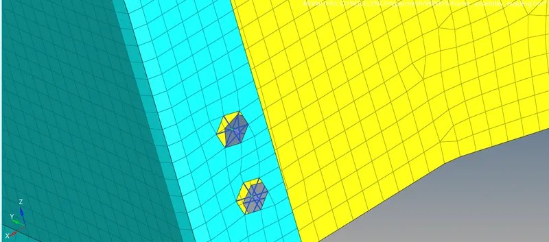
6. Rear_truss_2 & Left_Rail_2:- Bolt Connector
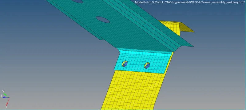
7.Right_Rail_1 & Right_Rail_2:- Spot-weld with Rigid Elements
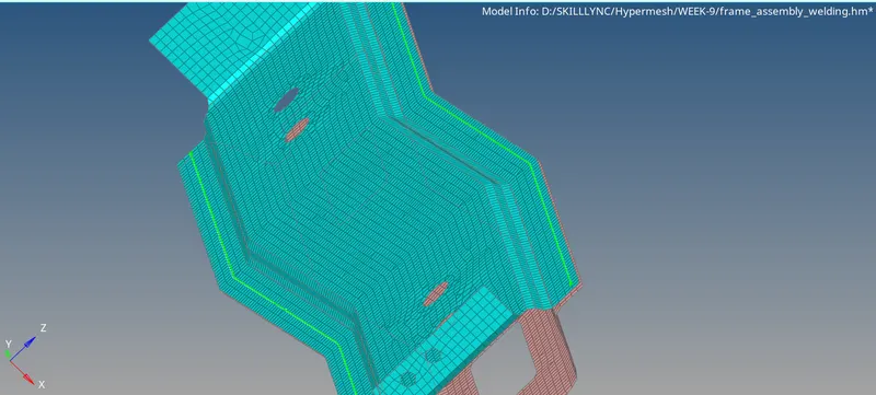
8. Left_Rail_1 & Left_Rail_2:- Spot-weld with Spring Elements