Week 9-Creation of 1D Connectors Challenge
Objective: To mesh the given component according to the quality criteria and to connect these components with the mentioned connectors.

CAD Model Image:
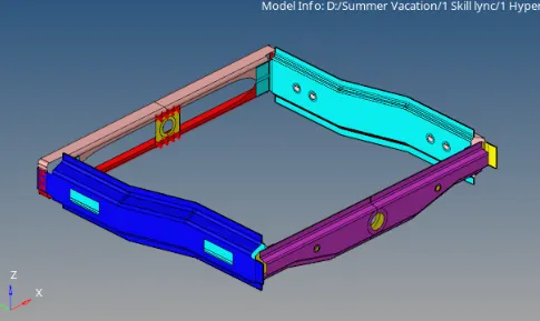
Procedure:
- Firstly, all the components need to be meshed by going to '2D->Automesh->elem size=5mm' . Using 'Quality index' and remeshing, all the elements needs to be meshed according to the given criteria as shown below:
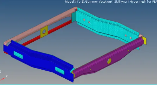
1. Right_Rail_2 & Front_truss_1:- Seam-Quad(angled+capped+L)
For this connection, activate the Right rail 2 and Front truss 1 components only. Then go to '2D->connectors->seam'. This type of connection is similar to 'Seam welding' two parts in real life. Under node path, select all the nodes on the 'edge' of the first component. In type, give the connector type as Seam-Quad(angled+capped+L). As the element size is 5mm, so give the spacing also as 5mm. The two components are less than 10mm apart so for tolerance, 10mm value should be given for proper connection. The weld angle can be set at default at 60 degrees, the cap angle can be set at 75 degrees and the runoff angle at 10 degrees. For mesh, select 'Quad transition' and 'imprint' option to rebuild the new mesh. Then click on create as shown below:
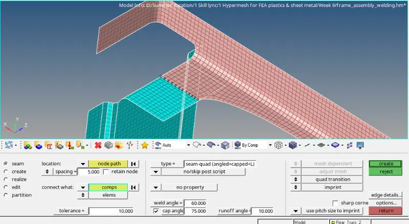 -->
--> 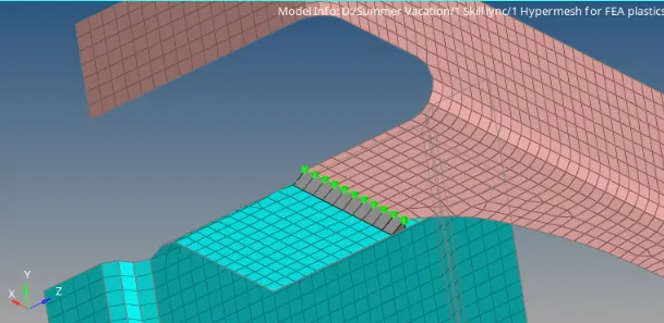
After creating the connector, it will be shown as a green-dotted line. This means that the connector is realised and it is correct. If a red-dotted line appears then, the connection needs to be realised by going to the 'connectors' tab.
The mesh will sometimes get disturbed. This has to be rectified by remeshing or going to 'quality index' and adjusting the failed elements.
2. Left_Rail_2 & Front_truss_1:- Quad elements
For this connection, activate the Left rail 2 and Front truss 1 components only. Follow the same steps by going to '2D->connectors->seam'. Select the type of connector as 'Quads'. Similar to the previous method, give spacing as 5mm. Both the components that are to be connected should be selected. The tolerance can be set at 10mm as these components are separated less than 10mm as shown below:
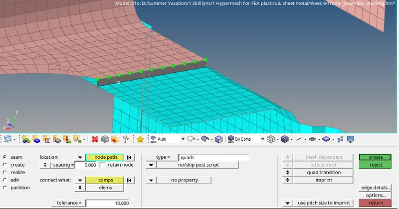
Again after such type of connection, there is a possibility that the mesh will get disturbed. This needs to be remeshed again.
3. Front_truss_2, Front_truss_1 & Right_Rail_1:- Spot weld with 3 Layers and 5 mm Diameter
This connection is between 3 components so all these 3 components need to be activated. Go to '2D->connectors->spot'. Select the nodes on the edge of the first component and then select all 3 components. Again the tolerance can be given as 10mm. Under type, give the default option as 'plot'. For the diameter of the spot weld, give the value as 5mm. Keep everything else at default as click on create to make the spot weld as shown below:
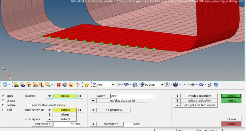
After spot welding, usually the mesh does not get affected so no need to remesh this area again.
4. Front_truss_2, Front_truss_1 & Left_Rail_1:- Hexa (Adhesive)
The given three components need to be activated and rest all can be hidden. Hexa (adhesive) connector is like glueing the components together using adhesives. For this, go to '2D->connectors->seam'. Type is selected as 'hexa(adhesive)'. Under location, select 'node path' and select two nodes at the edge. All the nodes in between these two nodes will get selected. This is a two step process as Adhesive connectors can connect only two components at a time. After selecting the nodes, select the first and second component. Then give tolerance as 10mm. Number of strips and coats is set to '1' and the width of the connector is also set to '1mm'. Same procedure is repeated for second and third component as well.
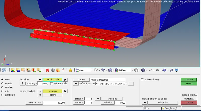
5. Rear_truss_2 & Right_Rail_2:- Bolt Connector & 6. Rear_truss_2 & Left_Rail_2:- Bolt Connector
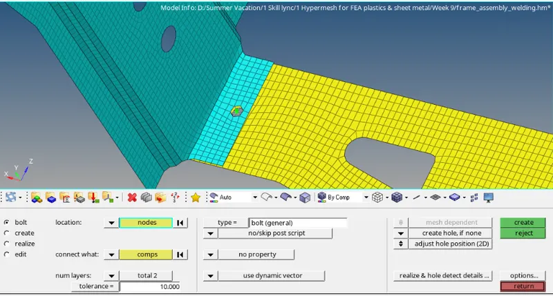
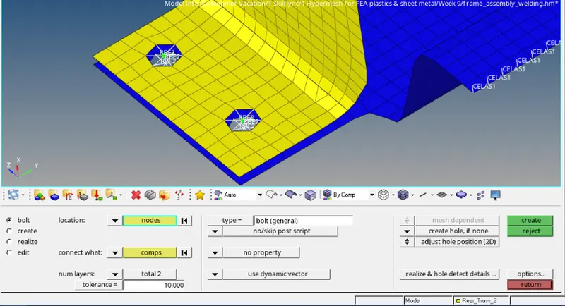
Activate Rear_truss_2 & Right_Rail_2 components and go to '2D->connectors->Bolt'. For location, select one node at the middle (one or two nodes can be selected). Then select both the components. Give number of layers as 'total 2' and tolerance as 10mm. Under type, keep it as default 'bolt(general)'. As there is no hole before, under the meshing part, select 'create hole if none' option. This option will first create a hole on both components and then connect them. This process of creating a hole disturbs the mesh. Therefore the mesh needs to be corrected again by going to '2D->quality index' or remeshing.
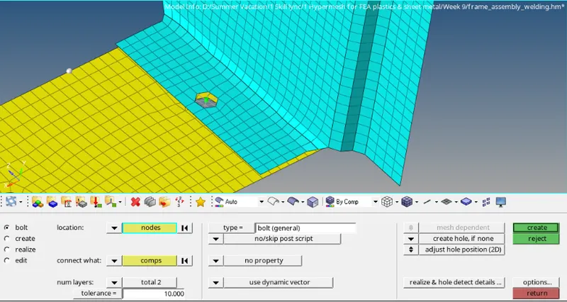
7. Right_Rail_1 & Right_Rail_2:- Spot-weld with Rigid Elements & 8. Left_Rail_1 & Left_Rail_2:- Spot-weld with Spring Elements
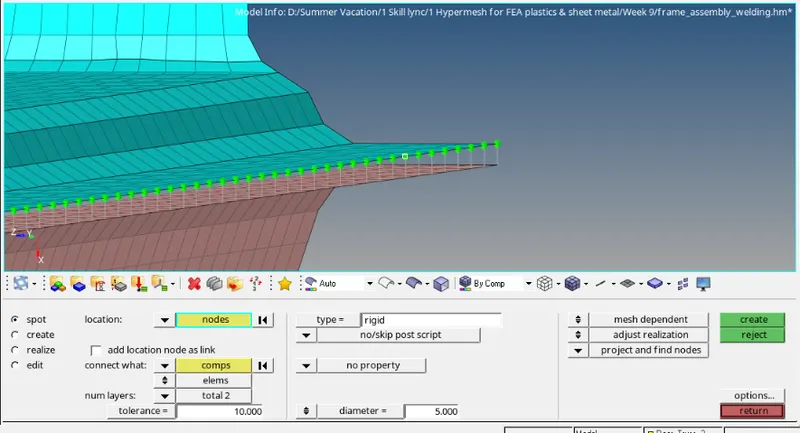
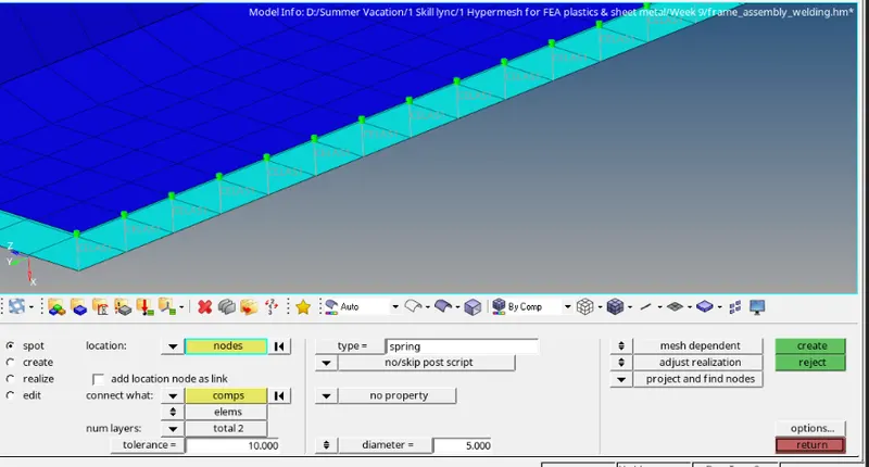
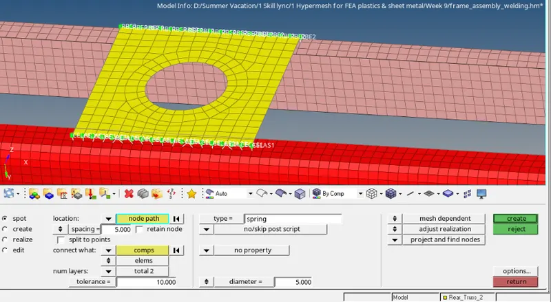
Activate Right rail 1 and Right rail 2 components. Go to '2D->connectors->spot'. Give element type as 'Rigid' and select all the nodes on the edge of the first component. Then select both the components under 'connect what' and give number of layers as 'total 2'. Set the tolerance at 10mm and diameter of spot weld as 5mm. Keep all other parameters at default and click on create. (Same procedure is repeated for Left rail 1 & 2 but the type is changed to 'Spring')
9. Rest all the component left Join them with suitable connectors
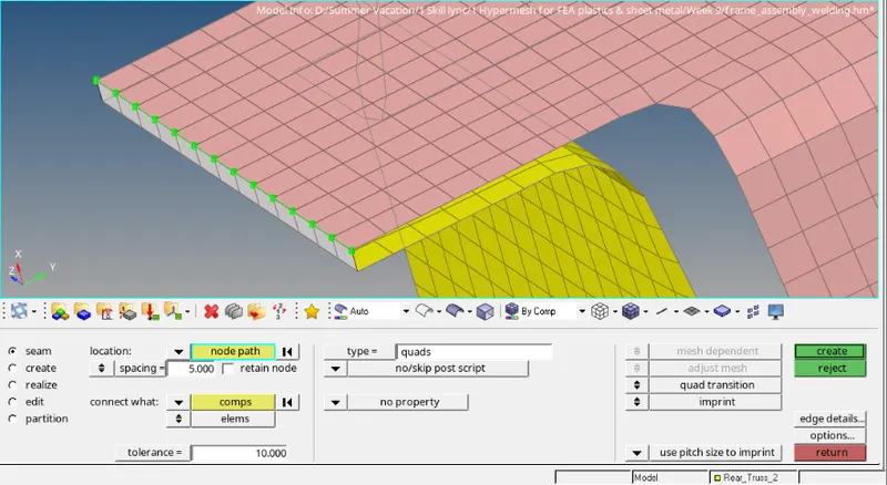
- Right rail 1 & Rear truss 2: These components are connected with 'Quad' type connector with a spacing of 5mm
- Left rail 1 & Rear truss 2: These components are connected with 'Bolts'. Two locations are selected and holes are created.
- Front truss 1, Front truss 2 & Reinf plate: Front truss 1 & 2 are connected with Reinf_plate with 'Spot' welding type connector. Spacing is given as 5mm and diameter is also given as 5mm.
Final Model Image:
As it is visible, all the connectors are green which means all the connectors are realised.
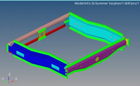
Results: The given components were successfully connected with appropriate connectors.