Week 4- Challenge
1. Mesh the Given component with the Size of 5mm. Create 1D elements on the following component with given cross-section and DOF
A1.
Objective: To Mesh the Given component with the Size of 5mm. Create 1D elements on the following component with given cross-section and DOF
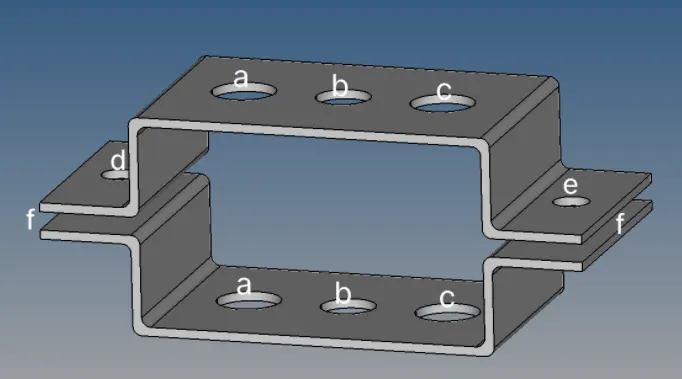
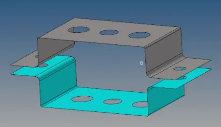
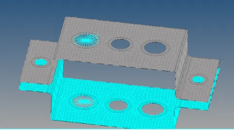
Cad model image:
Procedure with required images:
- Import the given CAD model and remove the wireframe geometry, lines and points that are not required.
- Now, create the mid-surface using the 'Midsurface' option in 'Geom' panel. In order to get the best mid-surface, under 'extraction' , select the 'skin offset' option. This will give a uniform and have proper corners and curves as shown below
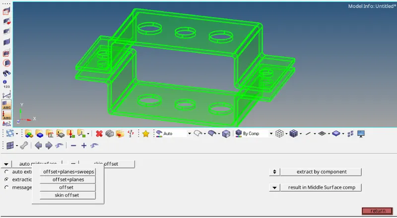
- First select the top bracket and then the bottom bracket to create a mid-surface then delete the solid model and only keep the new surfaces generated
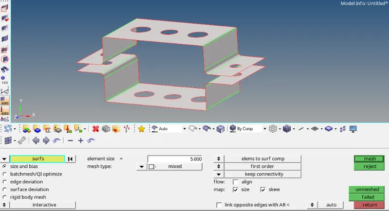
- Before meshing, the all holes needs to be given washer split of 5mm. Now select the 'Automesh' option in 2D and give the element size as 5mm and select both the surfaces.
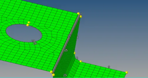
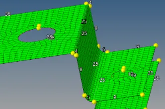
- After automesh it is observed that the edges/curves are not meshed properly. To resolve the issue, increase the number of nodes at these curves to a greater value. Also match the number of nodes around the holes and the washer splits.
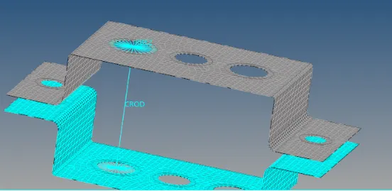
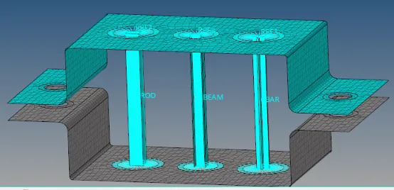
- The holes labelled as 'a' need to be given the following links: ROD element: Translational DOF should be Constrained with RBE2 link as shown below
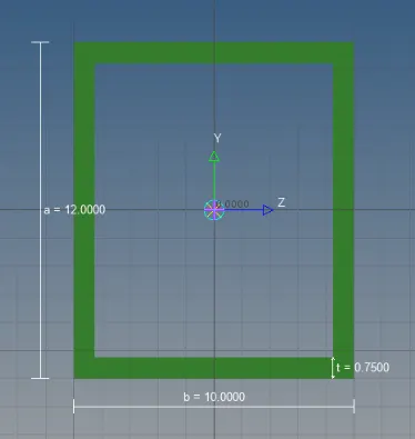
- In Hyperbeam, select thinwalled box and given the following dimensions:
Cross-Section: BOX- Dimension a= 12 mm
dimension b=10 mm
Thickness t= 0.75 mm
- Create a new property named 'box' and give the cross-section as 'box' and the material as 'Steel'
- Under 'Rods' select CROD and select the two nodes at hole 'a' and give the property as 'box'
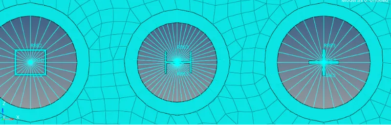
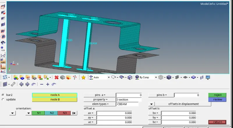
- The holes labelled as 'b' need to be given the following links: Beam element:- All DOF should be constrained with RBE3 link
- In Hyperbeam, select I section and given the following dimensions:
- Cross-Section: I Section- Dimension a= 8 mm
Dimension b= 10 mm
Dimension c= 8.5 mm
Thickness t1= 0.75 mm
Thickness t2= 0.6 mm
Thickness t3= 0.6 mm
- Create a new property named 'I section' and give the cross-section as 'I section' and the material as 'Steel'
- Under 'BARS' select CBEAM and select the two nodes at hole 'b' and give the property as 'I section'
- The holes labelled as 'c' need to be given the following links: Bar element:- Constrain only x and y DOFs With RBE3 link
- In Hyperbeam, select I section and given the following dimensions:
- Cross-section: X section- Dimension DIM1= 5 mm
Thickness DIM2= 1.2 mm
Dimension DIM3= 10 mm
Thickness DIM4= 1.2mm
- Create a new property named 'X section' and give the cross-section as 'X section' and the material as 'Steel'
- Under 'Bars' select CBAR and select the two nodes at hole 'c' and give the property as 'X section'
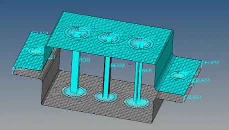
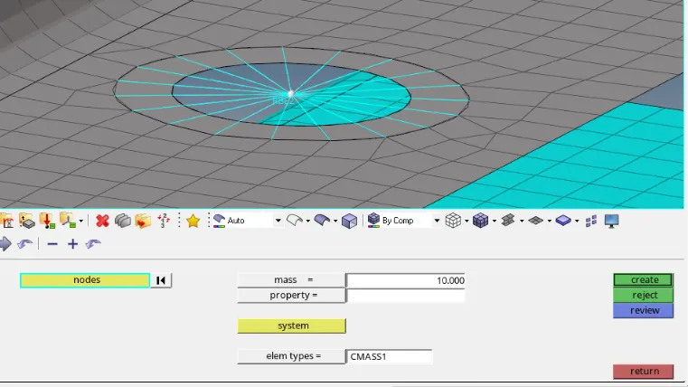
- For the holes labelled 'd' & 'e', select the nodes and create RBE2 links and under 'mass' option give mass as 'CMASS1' of magnitude 10 as shown below
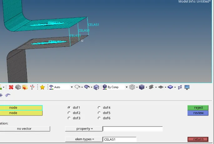
- For the edges labelled 'f' , select the nodes and under 'springs' option, apply the elem type as 'CELAS1'
Results and Final model image:
- The CAD model was converted to 2D geometry using mid-surface and the required constrains and element types along with cross-sections were applied as shown below: