Week 9-Creation of 1D Connectors Challenge
Creation of 1D Connectors
AIM:
- To deploy 1D connection for the given model using 'HYPERMESH'
OBJECTIVE:
- Mesh the component with the given Quality criterias and proper mesh flow.
- Create connector and Attach the various parts of the given model
CONNECTIONS
- Connections are nothing but representation of bolts, welds, rigid body, etc. in a FE model.
- As by its name those connector elements are used for connecting two parts.
- Here I have deployed various necessary connections.
Types of connections used here are,
- Bolt connection.
- Weld connection.
- Seam weld
- Spot weld
- ADHESSIVE Connections
- RBE2 elements (Manual representation for bolt or rigid body elements)
- RBE3 elemnets (Manual representation for bolt or rigid body elements)
In Hypermesh the realization of connectors can be identified by colours,
- Red - Error in realization of connections
- Yellow - Unrealized Connections
- Green - Realized connections
2D ELEMENTS QUALITY CRITERIA
|
S.N |
Quality Criteria |
Value |
|
1 |
Aspect Ratio |
5 |
|
2 |
Skewness |
45 |
|
3 |
Warping |
15 |
|
4 |
Taper |
0.5 |
|
5 |
Min. Length |
2 Units |
|
6 |
Max. Length |
8 Units |
|
7 |
Min angle Quad |
45 |
|
8 |
Max angle Quad |
135 |
|
9 |
Min angle Tria |
30 |
|
10 |
Max angle Tria |
110 |
|
11 |
Tria % |
15 |
Target element size - 5mm
NECESSARY CONNECTION DETAILS:
Create connector and Attach the various parts of the given model
1. Right_Rail_2 & Front_truss_1:- Seam-Quad(angled+capped+L)
2. Left_Rail_2 & Front_truss_1:- Quad elements
3. Front_truss_2, Front_truss_1 & Right_Rail_1:- Spot weld with 2 Layers and 5 mm Diameter
4. Front_truss_2, Front_truss_1 & Left_Rail_1:- Hexa (Adhesive)
5. Rear_truss_2 & Right_Rail_2:- Bolt Connector
6. Rear_truss_2 & Left_Rail_2:- Bolt Connector
7. Right_Rail_1 & Right_Rail_2:- Spot-weld with Rigid Elements
8. Left_Rail_1 & Left_Rail_2:- Spot-weld with Spring Elements
9. Rest all the component left Join them with suitable connectors
IMPORTING THE MODEL
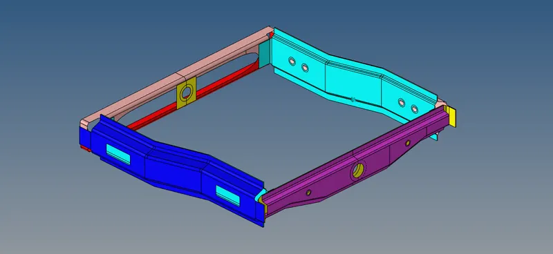
figure - Given CAD model
MESHING:
- Meshing has been performed for the given assemblies as per the quality criteria.
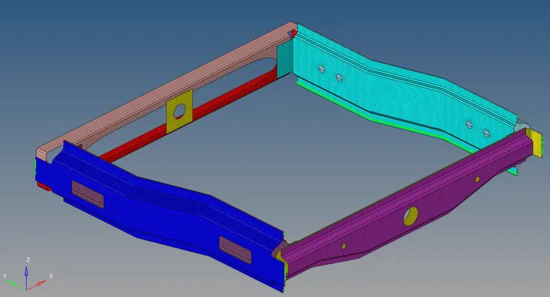
figure - Meshed with 5mm Target element
# Connectors created and attached the various parts of the given model
1. Right_Rail_2 & Front_truss_1:- Seam-Quad(angled+capped+L)
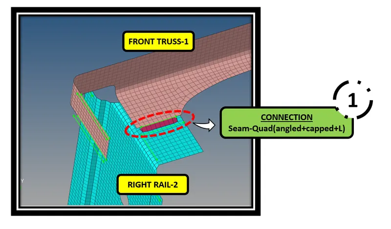

- 1D ---> Connectors ---> Seam ---> Type - Seam-Quad(angled+capped+L)
- Seam tab is attached in above image
2. Left_Rail_2 & Front_truss_1:- Quad elements
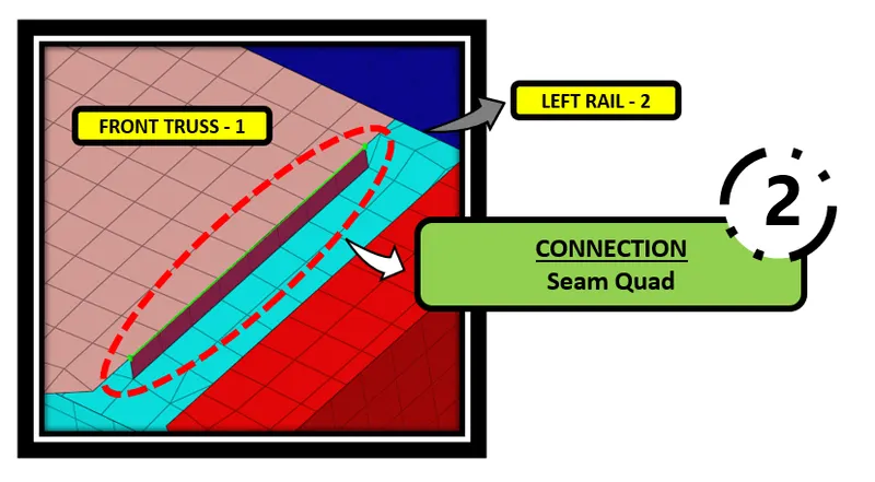

- 1D ---> Connectors ---> Seam ---> Type - Quad
- Seam tab is attached in above image
3. Front_truss_2, Front_truss_1 & Right_Rail_1:- Spot weld with 2 Layers and 5 mm Diameter
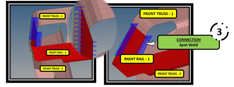

- 1D ---> Connectors ---> Spot ---> Type - weld
- Spot tab is attached in above image
4. Front_truss_2, Front_truss_1 & Left_Rail_1:- Hexa (Adhesive)
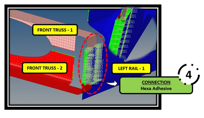

- 1D ---> Connectors ---> Seam ---> Type - Hexa(adhesive)
- Adhesive tab is attached in the above image
5. Rear_truss_2 & Right_Rail_2:- Bolt Connector
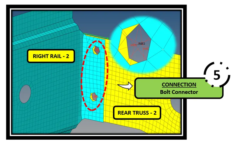

- 1D ---> Connectors ---> Bolt ---> (Create hole, if none)
- When there is a no hole in the FE Model, The create hole, if none option is used
- Bolt tab is attached in the above image
6. Rear_truss_2 & Left_Rail_2:- Bolt Connector
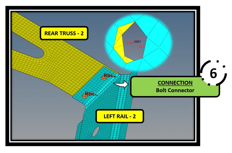
- 1D ---> Connectors ---> Bolt ---> (Create hole, if none)
- Bolt connection has been created.
7. Right_Rail_1 & Right_Rail_2:- Spot-weld with Rigid Elements
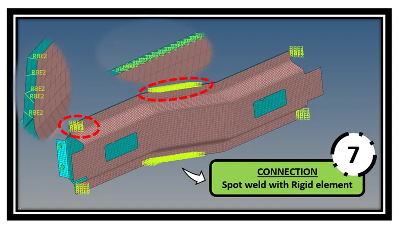

- 1D ---> Connectors ---> Spot ---> TYPE - Rigid
- Spot weld with rigid element tab is attached in above image
8. Left_Rail_1 & Left_Rail_2:- Spot-weld with Spring Elements
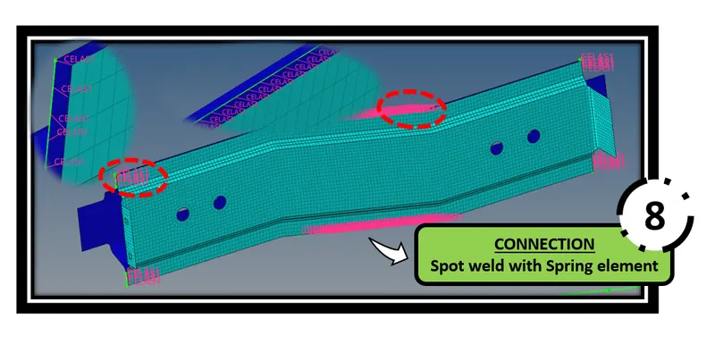

- 1D ---> Connectors ---> Spot ---> TYPE - Spring
- Spot weld with rigid element tab is attached below
9. Rest all the component left Join them with suitable connectors
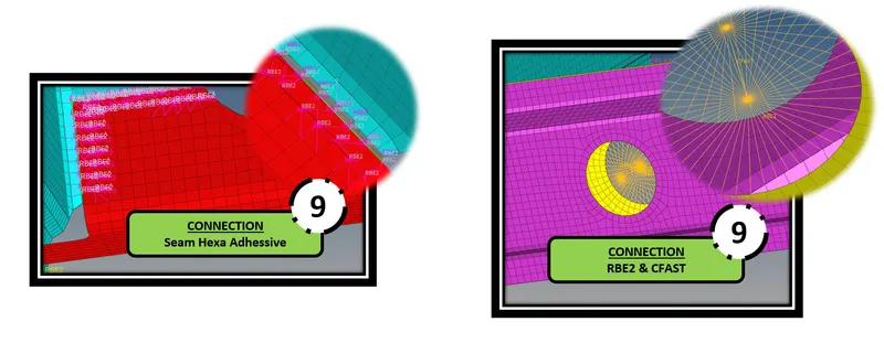
- Suitable connectors has been deployed in necesaary areas as shown in the below figure.
- Seam Hexa Adhesive is deployed by using Seam weld option.
- RBE2 is deployed by using Rigid option. Go to ---> Rigids --> Element = RBE2. Here I have arrested all DOF.
- CFAST is deployed by using Rods option. Go to --> Rods ---> Element type = CFAST
- PENTA (MIG) is deployed by using Seam option, Type = Penta (Mig)
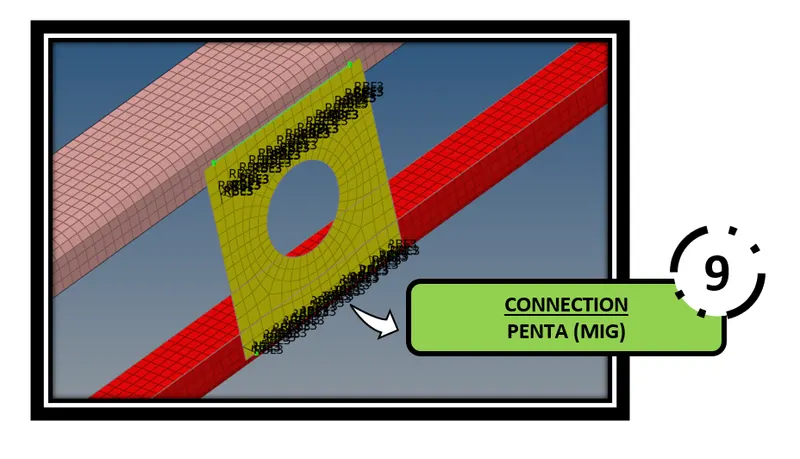


- PENTA (MIG) is deployed by using Seam option, Type - Penta (Mig)
FINAL RESULT:
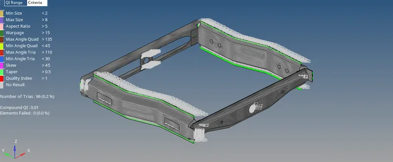
- Finally 'Zero' off elements has maintained
LEARNING OUTCOMES:
- At the end of this challenge, I can able to deploy necessary connections for automotive components.
CONCLUSION:
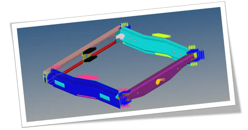
- The mesh has been performed by meeting the given quality criteria and also the necessary connections has been deployed successfully.