Week 9-Creation of 1D Connectors Challenge
AIM:
To extract midsurface and perform 2D meshing for the given components based on the given quality criteria and then perform connections based on the given criteria.
PROCEDURE:
- Import the given geometry and then perform the geometrical check and prepare the geometry for meshing.
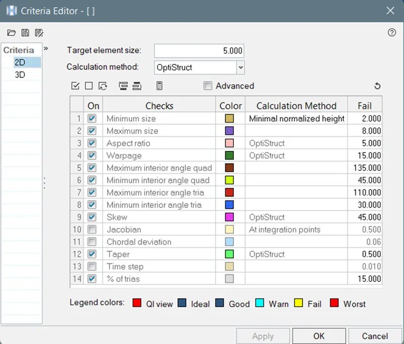
- Now go to preferences>criteria file setting>enter the required criteria>click apply>click ok.
- Now go to preferences>Parameters file setting>enter the required parameter values>click apply and click ok.
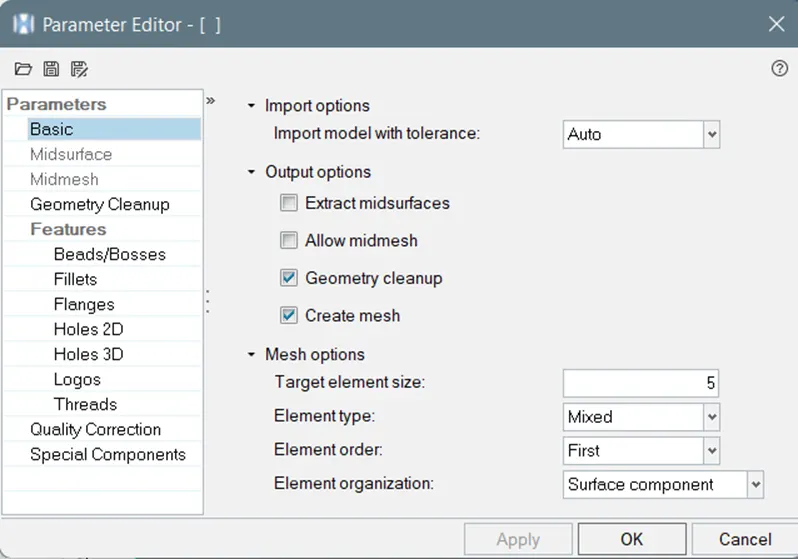
- Now go to automesh select the component by select the surface and check align and size check box. Enter the element size as 5 and mesh type as fixed.
- Similarly mesh all the compoenets and use cleanup tools to clear the elements failed for quality criteria.
-
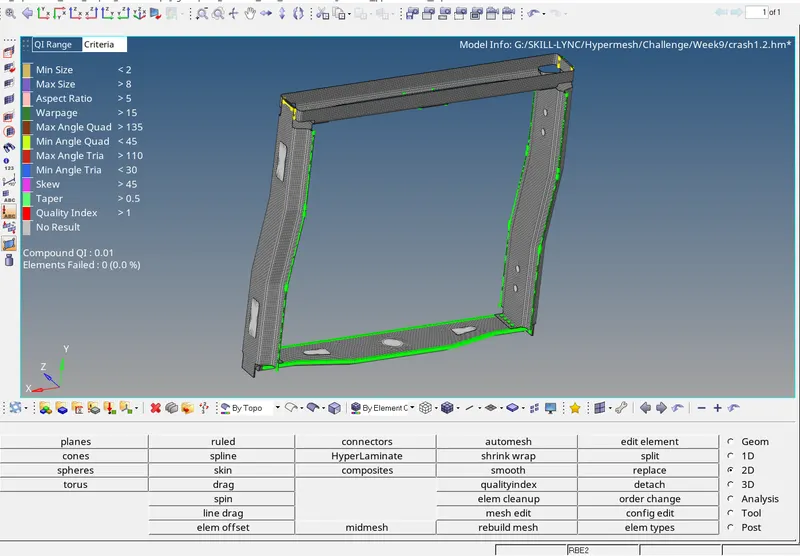
- Once you achieve zero percentage failed element then your mesh is perfect and now connection are need to be established between the components.
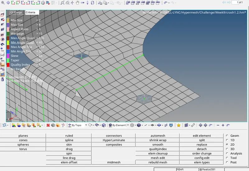
- It is given that between Right rail 2 and front truss 1 we need to establish Seam-Quad(angled+capped+L). For that go to 2D connectors>seam>Select the type as eam-Quad(angled+capped+L)>select remesh> enter the tolerence value as 15> enter the spacing value as target element length i.e., 5>Now select the component both source and target component.
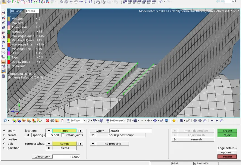
- Now show only front truss 1 and left rail 2 and hide remaining component. Go to 2D>connectors>seam>select type as quads>select the components>enter spacing value as target element length '5'>enter the tolerence value as 15>change quad transition to remesh to avoid element failure.
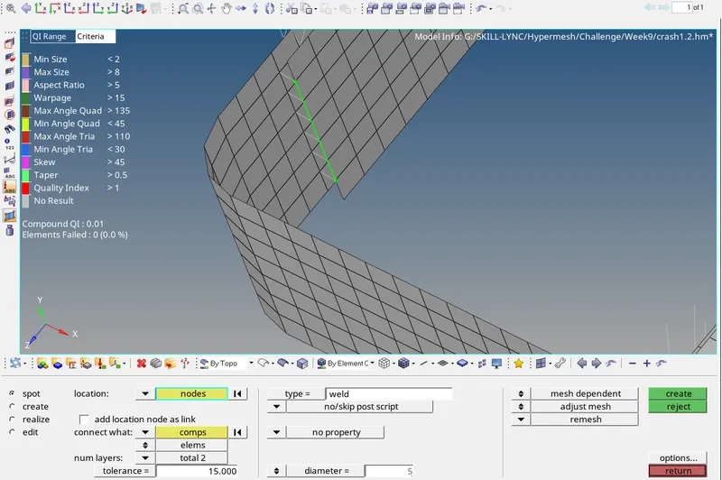
- For performing spot weld, first isolate the components that you need to perform the spot weld. Now go to 2D>connectors>spot>Select type as weld>enter the tolerence value as 15>enter the diameter as 5mm as given>select 2layer>select the components>instead of adjust realization select adjustmesh and select remesh>click create.
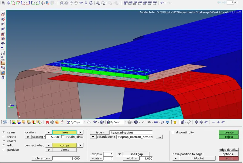
- For hexa(adhesives) go to 2D>connectors>seam>select type as hexa(adhesives)>enter spacing as target element length>enter the tolerence value as 15>select the components>click create.
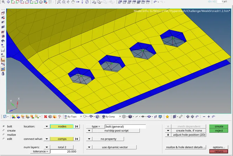
- For bolt connectors go to 2D>connectors>bolt>Select the nodes>select type as bolt(general)>select the components>select the tolerence value as 15>instead of "considering existing hole only" select "create hole, if none"> select the number of layer>click create.
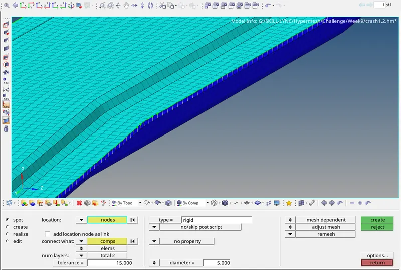
- For creating spot weld with rigid elements go to 2D>connectors>spot>select type as rigid>select the components>enter the tolerence value>enter the weld diameter>instead of "adjust realization" select "adjust remesh"> click create.
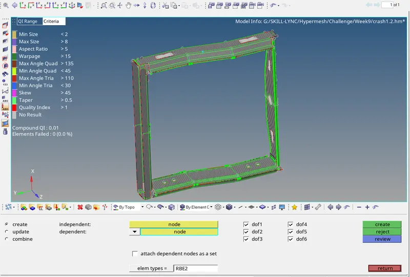
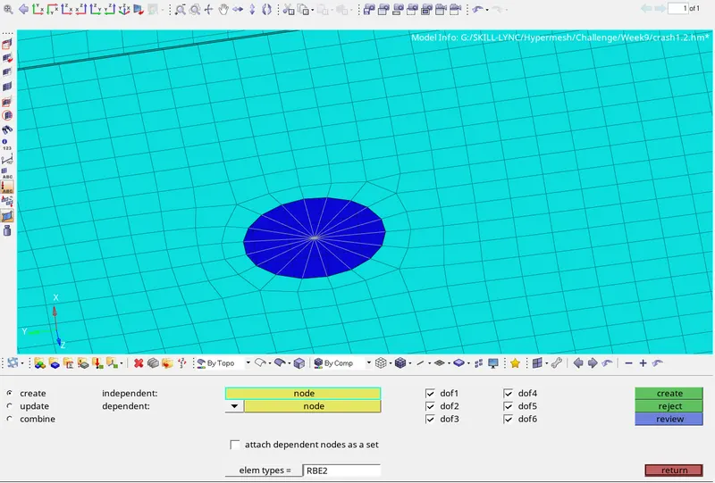
- For holes present in the component perform rbe2 connection before that we need to create the COG point for the hole for that go to geometry>nodes>arc centre>select the circle>click create.
- Now go to 1D>rigids>select the COG point as independent node>select the nodes in the circle as dependent nodes>check all the degrees of freedom inorder to create rigid connection>click create.
RESULT:
Thus for the given model 2D meshing is performed and then connection are established between the components as per the criteria.
COMPLETED MODEL: