Week - 8 - Morphing
AIM:
To do morphing on the given both models and for the model 1 do morphing by using all the technique as you saw in video and for model 2 do morphing only for the specified components in the model.
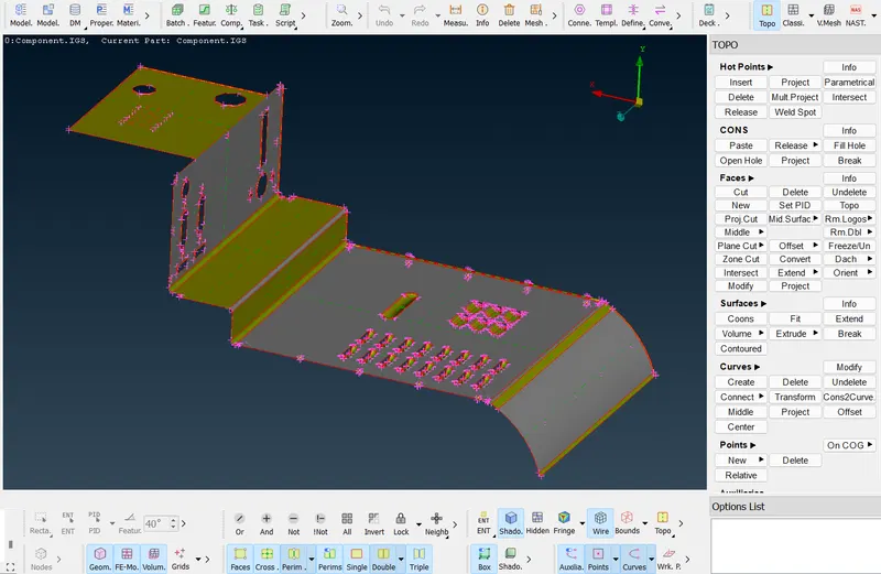
GIVEN CAD MODEL:
PROCEDURE:
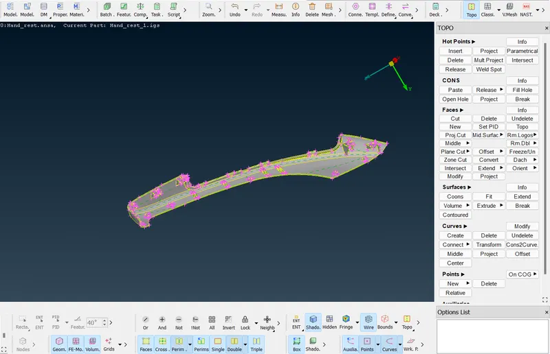
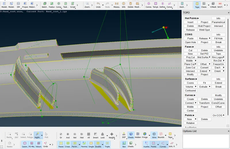
- Since this model is in .igs format we have to perform topo to make the connections between the components for that go to Topo module -->faces --> Topo.
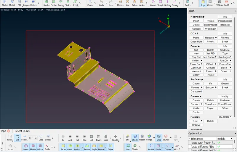
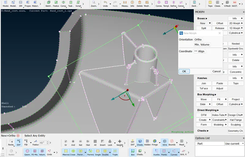
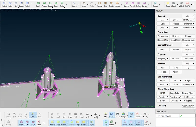
- To perform morphing go to classic morphing module and click new, in the drop-down box select the ortho and select the component, once the box is displayed align it based on the requirement using align option and click ok.
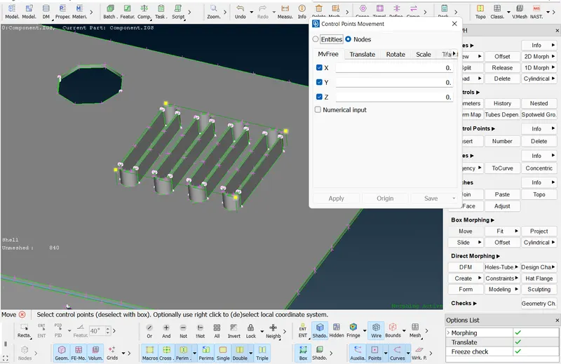
- Use function keys to switch to required views to select the component. Once you've created a morphing box go to box morphing and click move and select the points in the box that you want to model. In the control points movement uncheck the axis that you want to constrain. Once you have done Morphing click apply and check the geometry whether all the face status are either in or out if it is collapse change to in or out and click next and click finish now drag the model in either direction to perform Morphing.
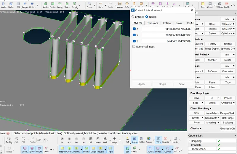
- Similarly set up box and use move option to perform morphing on the different component as shown below
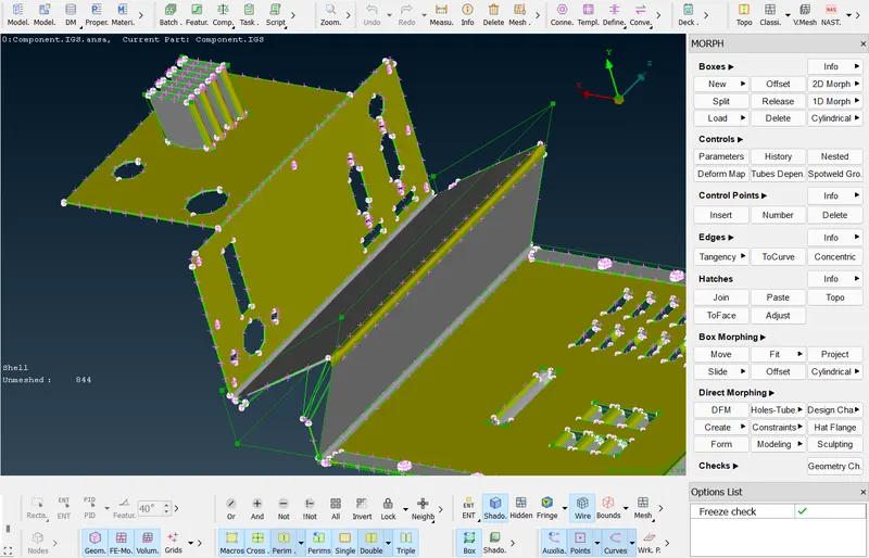
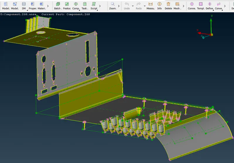
- For selecting similar components with same cross section, use function key to set the required view and box select all the similar components and set up box using boxes--> new -->ortho and align it and click ok. Use move and select the control points and apply constrain based on the requirement and perform morphing.
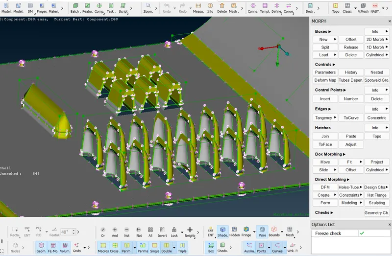
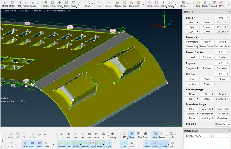
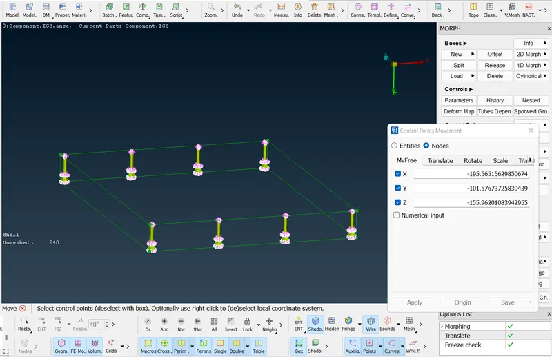
- similarly for the bolts. Use lock view to view only bolds and go to boxes-->new--> ortho--> and box select the bolts and click ok. Now go to Move and select the control points of the box and check all the faces are either in or out and apply. Then drag the mouse to perform morphing and click ok.
MODEL 2:
GIVEN CAD MODEL:
- Then the given model is in .ansa format so no need to perform topo. Once you check the geometry go to classic morph under boxes go to new-->ortho and box select the component and deselect the extra surface that you don't need to morph using right click box selection.
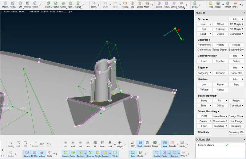
- Our aim is to perform morphing on only the dog hoses and ribs so deselect the extra surfaces. Now under box morphing go to move and select the control point of the box and check the status of faces as either in or out and constrain the direction of morph by unchecking the axis and click ok. Now drag the mouse to perform the morphing.
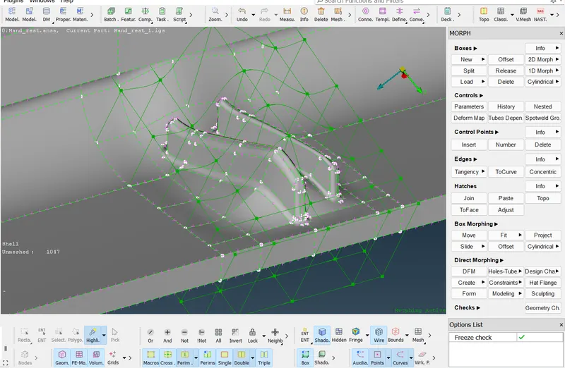
- For performing morphing on the ribs we gonna use boxes and then we split into different segments and then we gonna move the particular segment which contains rib portion. First go to topo module under face go to place cut and select the plane by clicking on the coons and select the faces to cut and then click ok
- Now go to classic morph module and under boxes click new-->ortho--> select the surface-->align it based on requirement and click ok. Now under boxes use split options to split the created box into one of the required sections. Now go to move option and select the constrain points and check the faces and constrain the movement by unchecking the axis button and drag the mouse.
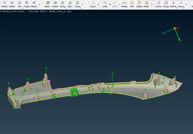
- Similarly perform morphing for all the dog hoses and ribs as mentioned above.
COMPLETELY MORPHED MODELS:
APPLICATIONS OF MORPHING IN INDUSTRY:
Mesh morphing consists of the adaption of a computational grid adopted for computer aided engineering (CAE). For instance, the solid or shell mesh of a structural part ready to be processed by an FEA solver, or the volume mesh complete with boundary conditions for a CFD solver, can take a new shape by just updating nodal positions. This means that the topology of the mesh (nodes count, cells count, connectivity) stays the same. Only the x,y,z coordinates of the nodes in the part of the model undergoing a shape modification are updated.
Mesh morphing can be used for different purposes: create shape parameters (i.e. change a length, an angle a thickness), move onto a new known shape (i.e. as manufactured, as designed by CAD), move onto a shape predicted by the CAE solution (automatic shape optimization with adjoint or BGM), and/or support multiphysics (move CFD mesh according to the evolution of the FEM-connected one, enable erosion/deposition).
Usually mesh morphing is faster than remeshing for a number of reasons: it avoids “remeshing noise” (having the same mesh adapted means the effect of a parameter is not confused with the effect of a new mesh structure), so variation effects can be assessed even with a coarser mesh. The CAE model can be updated on the background keeping all the original settings (boundary conditions). The update of nodal positions usually requires less computational efforts vs a full mesh regeneration. Creating shape parameters with mesh morphing is faster than creating a parametric CAD model.
Result:
Thus, the morphing is performed on both the models based on the requirement and applications of morphing in industry are listed above.