Week 6 - Creating connection for Rear door
AIM:
To create and apply different PID for the side door component and perform the suitable connections.
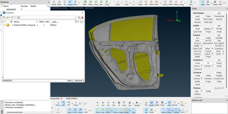
GIVEN CAD MODEL:
PROCEDURE:
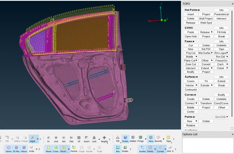
- The given component is in one PID. So the first thing is we need to set PID for each component and no need to assign the thickness. For that use feature option to select the particular entity for setting the PID. After that go to not option and click on the component and then invert it.
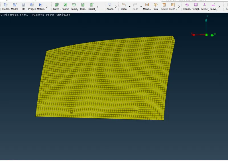
- Now you can have only that component then go to topo module under faces click on set PID and box select the eitire thing and middle click and in the property manager create new PID and rename it as the selected component name and click ok.(no need to assign the thickness)
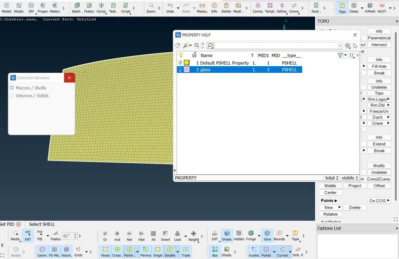
- similarly for all the component use not and feature selection to select the particular component and perform the above steps. After setting the PID for all the component it look like as shown below.
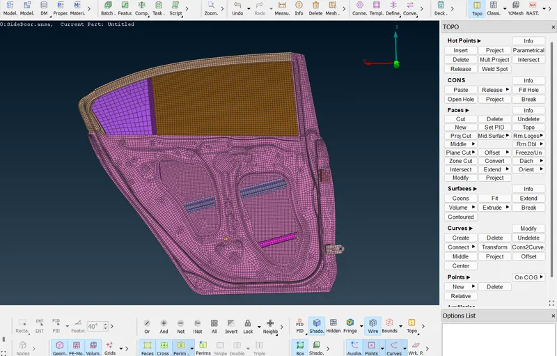
- First, we are going to create a CBUSH connection between the glass and door frame. CBUSH connections are used where the soft rubber materials are used between the components to isolate the system from the surroundings.
- Second, we have to create a curve using the feature2curve option for that go to mesh>parameter>Feat2Curve option in the feature selection type the angle as 10 degree to select only the 10 degree elevated lines in series. and click ok.
- Follow the same for all four sides. Once the curves are created, we need to convert them into the spot weld line. And convert all the four curves into a feature line.
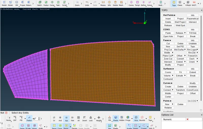
- Once the spot weld lines are created go to the connection manager and select the sot weld line and then give a middle click.
- Now specify the spacing value as '10' and the for selecting the parts click on P1, in modify right click and use the PID selection option to select the required part. Similarly for the next part.
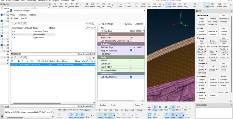
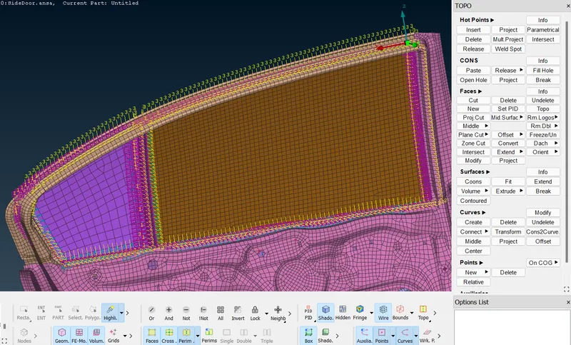
- You can follow the same steps for all the CBUSH connections. Now the CBUSH connection we have done is not aligned and so we are going to modify all the CBUSH connections with respect to the global coordinates.
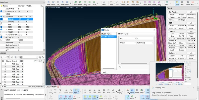
- For that in the database double click on CBUSH, in the show or hide column select the orient and cid column. Now select all the CBUSH id and click modlfy. Put cid value as zero and orient as with cord and then click ok. Now all the CBUSH connections are aligned with respect to global coordinates.
- For the weight reduction holes use RBE2 connection to make rigid connection while solving. For that go to nastran module and under elements select RBE2 element and then select the hole by using loop selection option and then click ok.
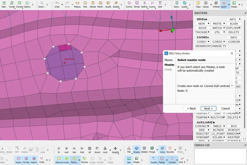
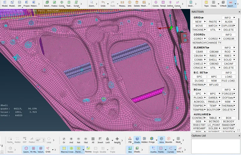
- Set new part and save all the connection under that and then click finish. Similarly do for all the hole that are made for weight reduction.
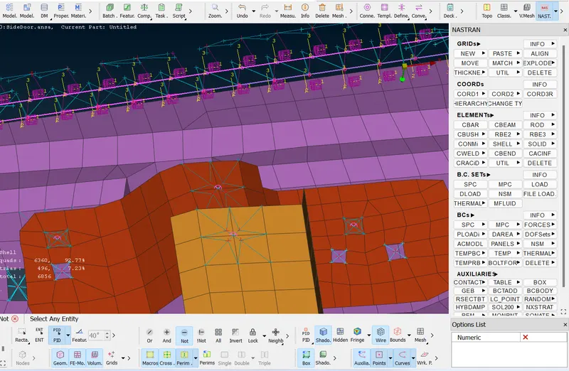
- For spot weld areas, create COG by selecting the element and then going to convert option and then selecting the convert 3D point into spot weld. now go to connection manager and then select the spot weld that we have created by convert option. select the two PID which we are going to create spot weld in-between. In drop-down box select Rbe3-Hexa-Rbe3 and then give the search distance and then create a weld pid and set a name as spot weld and then click ok. In connection manager click apply and then click realize.
- For representing handle as a connection. use RBE2>MULTI and then use loop to select the hole and click apply, after setting the PID for RBE2 connection click ok. Similarly for the other holes. After applying RBE2 connection for two holes of the handle create RBE2 two node connection to apply coon mass.
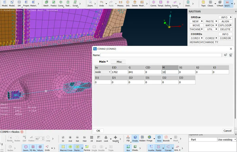
- Under elements go to CONMi-->CONM2--> Select nodes and then select the middle node of the two node connection betwenn two RBE2s and then apply and enter mass as 0.001, because the unit is in tonne so if you enter 1 it take it as 1 tonne.
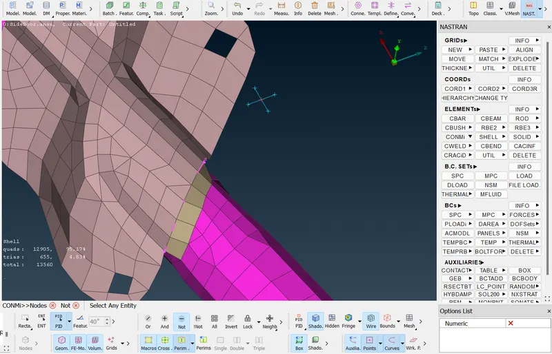
- For creating a seam line. first use feat2curve option to convert the entity into a curve and then convert the curve into a seam weld line using convert-->curves-->seam line option. Now to connection manager and select the seam line and middle click and then select the p1 as the thickest area as it is the base area and then select p2.
- In the drop-down box select (overlap shell) as the two surfaces are parallel to each other. Then give the search distance and then choose the proper base sheet and then give the step value and width of weld value as a target element size and then create a new pid as seam weld and then click ok
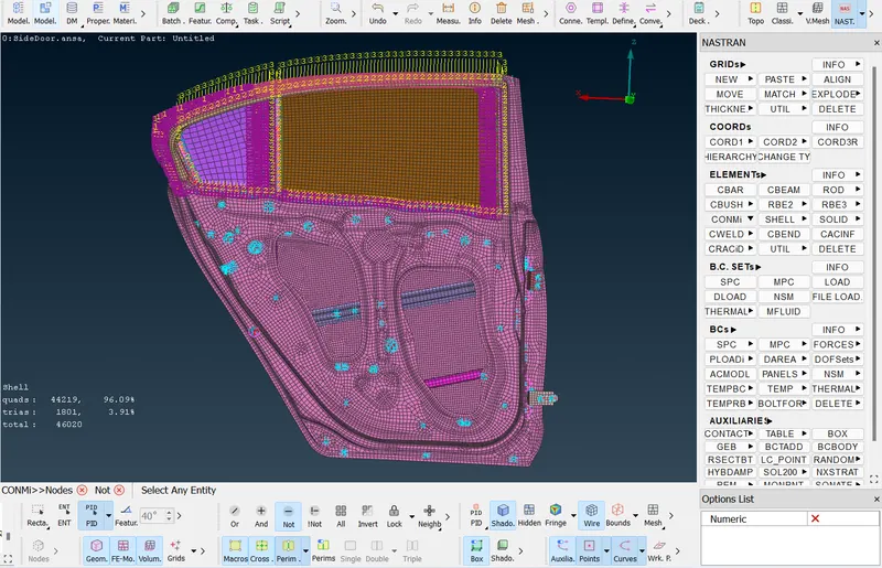
COMPLETED MODEL
RESULT:
Thus, for the given model the different PID is assigned for different components and then connection are made between the components and now the model is ready for use in solver.