Week- 5 - Solid meshing
AIM:
To check the geometrical errors and mesh the surface for the given Rear view mirror component under the specified element quality criteria.
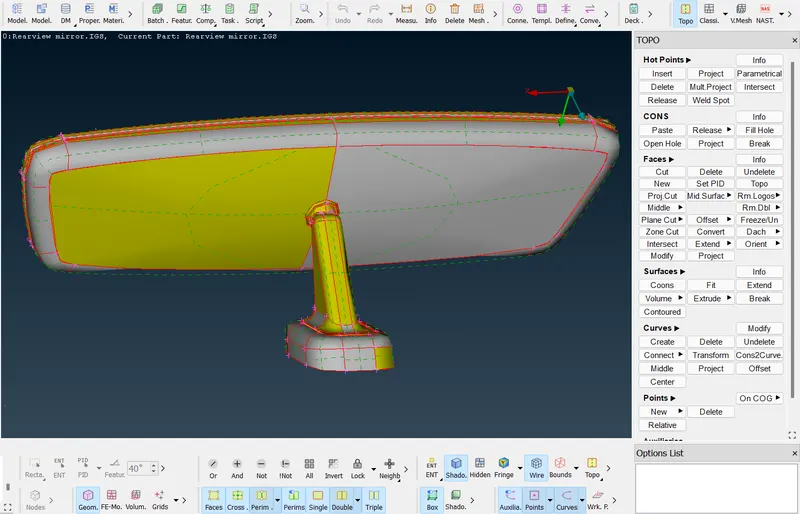
GIVEN CAD MODEL:
PROCEDURE:
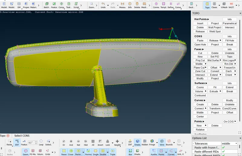
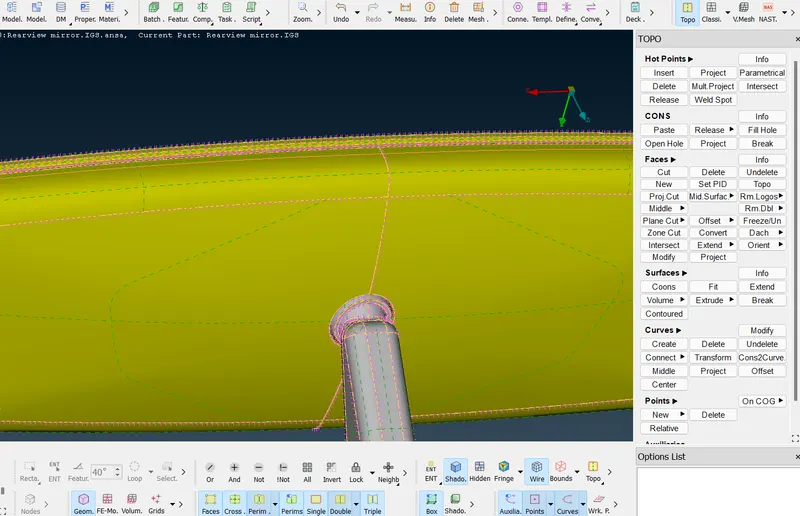
- The given model is in .IGS format, so the model cannot have any connections between the components. After the model is opened go to topo module under faces click on topo and select all the elements and give a middle mouse click.
- Now all the components have connection in between and the coons are appeared in yellow color.
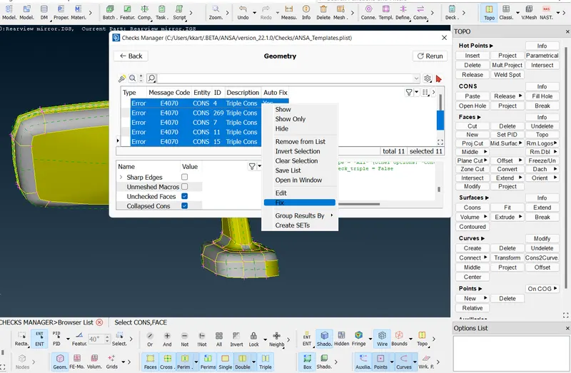
- Now go to check-->geometry and click the execute to check the entire geometry. After execution if it show any errors, select all the error and right click and select fix only if auto fix is available.
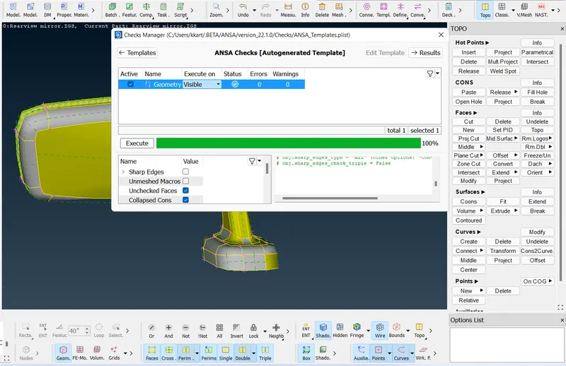
- Once you click fix, ANSA will auto fix all the errors and then click rerun, if there is no error the status shows green tick. If auto fix is not available, you have fix all the errors one by one.
- Now to get the correct resolution and to set the target element size between the component go to mesh module under perimeters -->length-->box select the component and click ok and similarly for macros.
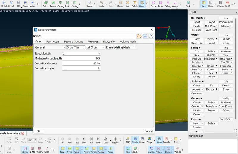
- Now go to mesh parameters and select the target element size as '1' and minimum and maximum element size as 0.5 and 2. select ortho trias instead of mixed. Because ortho trias can capture fillet and curvy areas accurately and without any dip on the surface. Now go to quality criteria and specify the minimum and maximum element size and give collapse value as 0.2 under psolids.
- Now do geometry cleanup using macros--> join option to avoid element failure. Use measure option to measure the element size if the measured element size is lower than the target element size use join option to clean up the geometry.
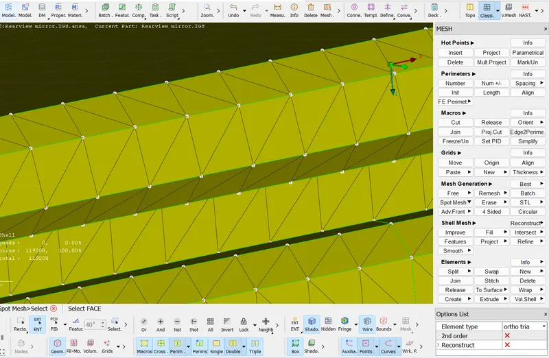
- Once the geometric cleanup is completed go to mesh module, under mesh generation select spot mesh-->select in the options list ensure that the element type is mixed. Select all the fillet areas in the component and then give a middle mouse click. Use reconstruct option on the particular macros where the element failure would occur.
- For a flat surface use tetra element for meshing for that go to spot mesh --> select, in the option list select element type as trias and select the macros and give middle mouse click.
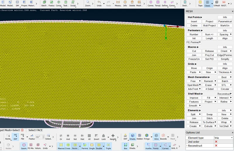
- The reason why we are using trias for flat surface is, the ortho tria is the ideal required mesh but it takes more time to solve so to reduce the solving time we are using trias on flat areas where the element failure will not occur and we use ortho trias on the curvy surfaces or the surfaces which are hard to capture.
- So now the meshing is done for all the components in the model and click save.
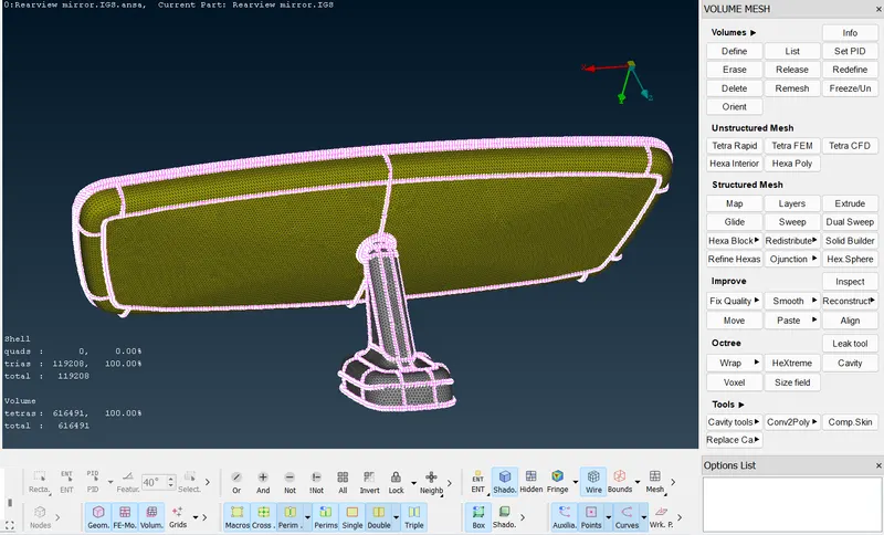
- Now we are going to generate a volume mesh from the surface mesh we have generated. For that go to volume mesh module and then first define the model by using volumes-->define-->visible and click ok. Now go to volumes --> list, there you can find the no of volumes detected and the mesh status of that volumes. Now set PID for all the volumes.
- Go to tetra rapid and select visible and now the volume mesh is created using the tetra rapid algorithm. You can use the not option to check the volume mesh created.
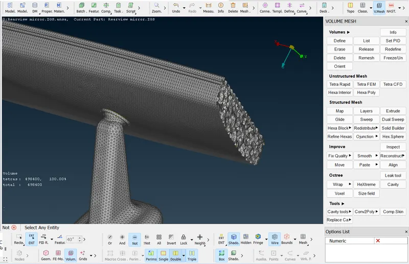
- Now go to mesh module under grids select MV free option to correct ted collapse and dip on the surface.
COMPLETED MODEL:
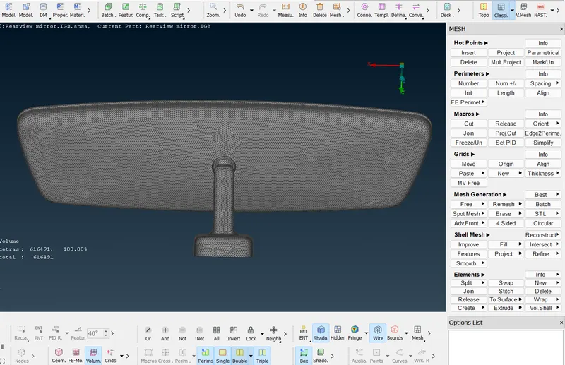
Result:
Thus, the solid mesh has been generated for the give Rear view mirror component based on the given quality criteria.