Week 9-Creation of 1D Connectors Challenge
Aim: To create connectors for various parts of the given model as per the given quality parameters.
Solution:
Steps:
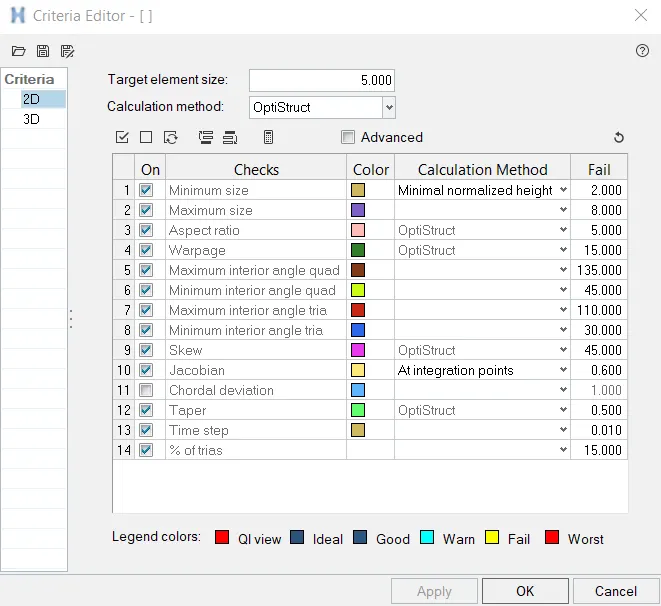
- First, download & import the model in Hypermesh. Then update the criteria file settings & 2D mesh the model.
- Next check for mesh quality, correct any errors, and create the connections as mentioned in the challenge.
- Finally. create the necessary connections between the components and Save the model.
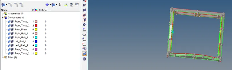
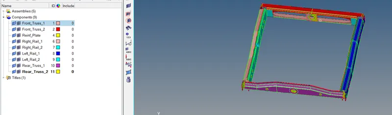
- After meshing the components, the model contains a total of 9 midsurface components formed.
- Navigate to 2D -> Automesh, and enter the element size as '5' and mesh type as 'mixed'. Make sure to change the elements to surface components.
- Select all the surfaces and then click on mesh and then accept the mesh.
- We now check for the mesh flow, correct it and check for mesh quality. Navigate to 2D -> Qualityindex.
- It displays the number of elements that failed and also the elements will be highlighted.
- Correct the mesh by using Smooth, Element optimize, Drag tria element, and Combine tria elements. Navigate to Mask -> Elements and then click on mask and then reverse all.
- The mesh can be corrected using the options available in 2D such as Rebuild mesh, Remesh in automesh, Edit element, Replace, etc.
- To make the connections go to 2D -> Connectors; This option is used to create Seam, Spot, and Bolt.

- Use Spacing to give space between connectors and check to retain node to keep the node even after the connector is created.
- Hexa position to the edge has four options: Midpoint(adhesive midpoint in nodes), Positive edge(adhesive outside from node), Negative edge(adhesive completely inside a node), and Offset.

- In a bolt, the number of layers represents the number of layers to be connected. First create a hole, if none (create a hole in the elements only not on the surface if no hole is present on the surface).
- Use a hole if available, Fill and remesh hole if available and after creating the hole, The surface can be turned on so that we can understand that the hole is not created in the surface.

- In spot weld, it will ask for weld diameter. For that Project and find nodes will project to the next layer and find the nearest node. Adjust realization & Adjust mesh is one type of option available they are used in the realization of the connector fails.
- Mesh dependent & Mesh independent is other types of option available. All component layers are at a distance of each by only 3 units hence tolerance is given as 10. In the case of 3 layers, the distance between the top & bottom layer is 6 units.

- Spot-weld with rigid and springs is available under 1D -> Spotweld; Their element config as rigid & spring. Using the nodes option connection has to be created. Here nodes are to be selected from two layers. Dependent node from one layer and independent node from one layer.
- To select multiple nodes nodes-nodes are to be selected. Then using ctrl+left click on component highlight them (components to be made connection) in tab area and then holding ctrl+right click -> isolate only.
- This will show only the components to be connected.
- Similarly, do these steps for all connections.
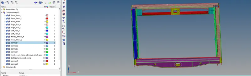
CONNECTOR IMAGES :
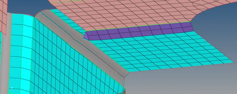
seam-quad (angled and capped with L)
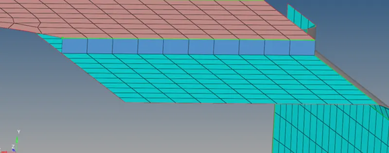
Quad elements
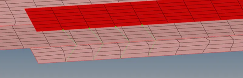
Spot weld dia 5
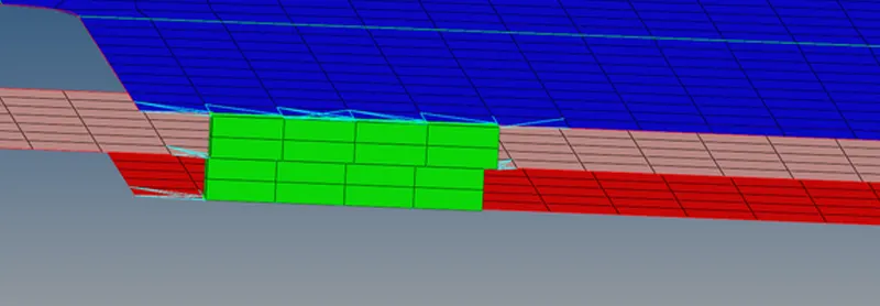
Hexa (adhesive)
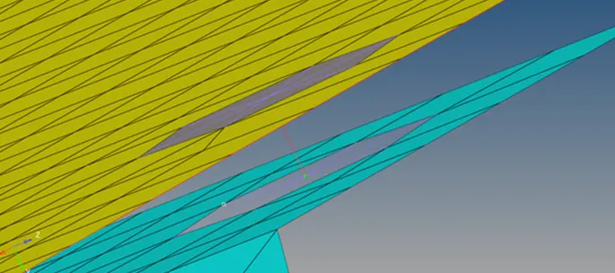
Bolt connector
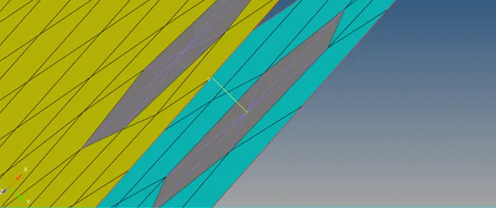
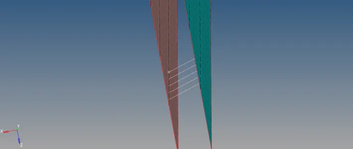
Spot-weld containing rigid elements
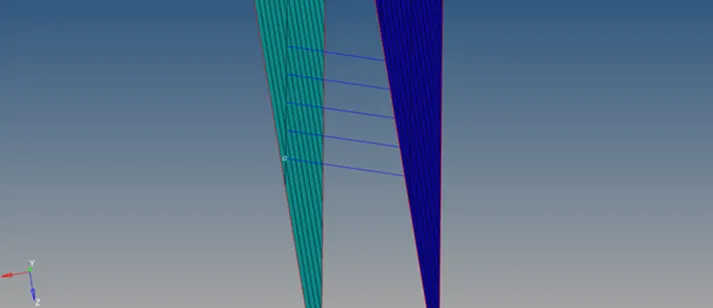
Spot-weld containing spring elements
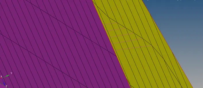
Spot-weld containing rigid elements
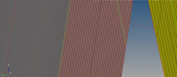
Spot weld dia 2
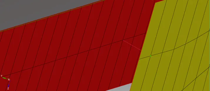
Spot weld dia 2
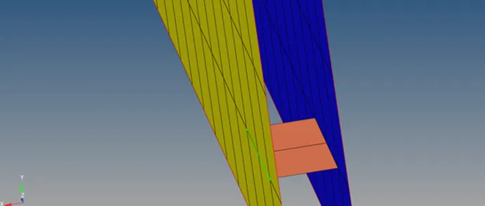
Quad elements
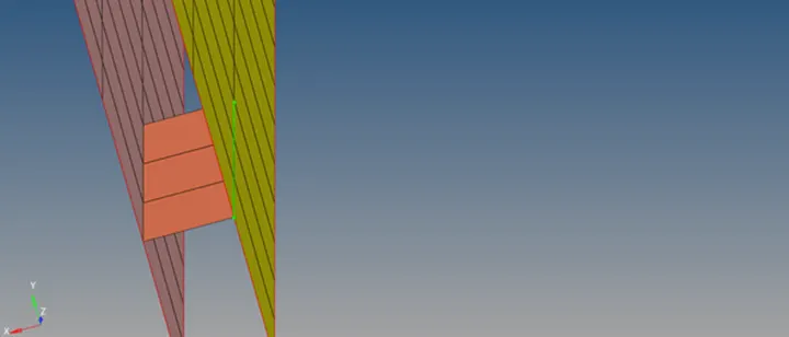
Quad elements
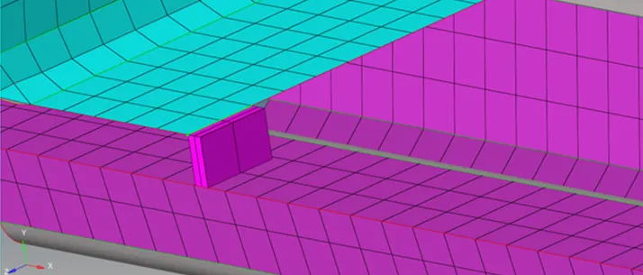
Hexa (adhesive)
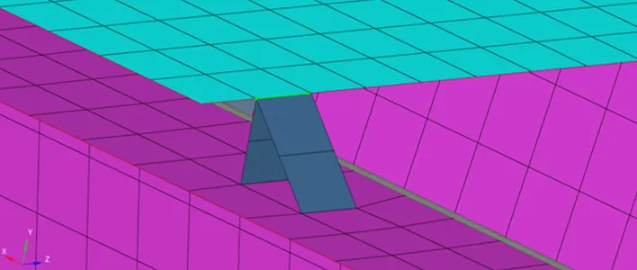
Seam-quad (vertical and angled)
Final Image:
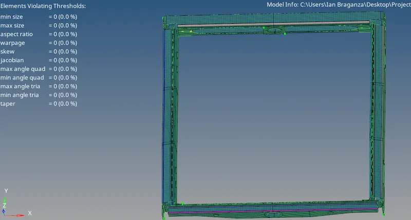
Conclusion: The challenge was successfully completed as per the given requirements.