Week -2
Aim: To simulate a doorbell and heater using Simulink
Objectives:
1. To observe the physical movement of the plunger when the switch is closed for 2 seconds and then released.
2. To use a thermistor to sense the temperature of a heater and turn on or turn off the fan as per below conditions:
Temperature source: 20 °C from 0 to 10 seconds, 27 °C from 10 to 30 seconds, 23 °C from 30 to 50 seconds
Fan conditions: ON if the temperature above 25 °C, OFF otherwise
PART 1:
Procedure/Steps:
1. An input signal is given to the model.
2. A Simulink-PS Converter is used to convert the input Simulink signal into a physical signal.
3. A switch is connected to the battery and solenoid.
4. When the external physical signal PS is greater than the threshold, the switch is closed, else the switch is open.
5. A Solenoid is used to convert electrical signals to mechanical signals.
6. The Ideal mechanical translational motion sensor converts an across variable measured between two mechanical translational nodes into a control signal proportional to velocity and position.
7. A PS-Simulink Converter is used to convert the physical signal into a Simulink output signal.
8. The Solver Configuration block specifies the solver parameters that the model needs before the simulation is begun.
9. Finally, the Scope and Display are used to obtain the output plots.
Model: Below is the Simulink doorbell model for the plunger movement 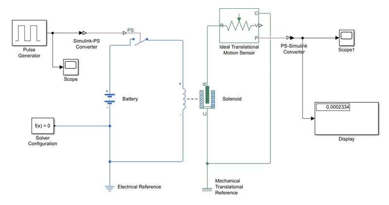
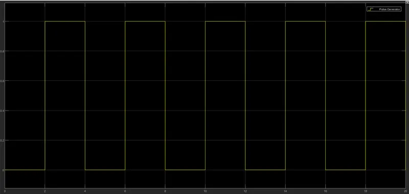
Input: An Input of Amplitude = 1, Period = 4 sec, Pulse Width = 50% and Phase Delay = 2 sec is given
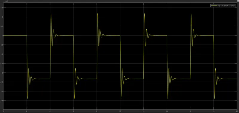
Output: A plot for m = 0.1 kg and t = 20 sec
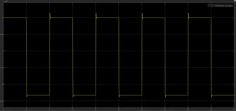
A plot for m = 0.01 kg and t = 20 sec
PART 2:
Procedure/Steps:
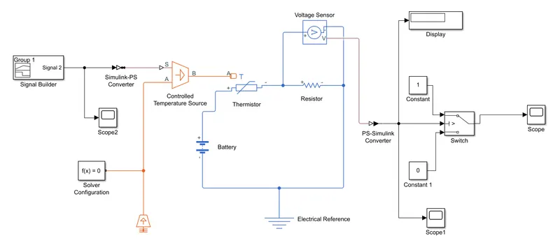
1. A signal builder is given according to given conditions (20 °C from 0 to 10 seconds, 27 °C from 10 to 30 seconds, 23 °C from 30 to 50 seconds
Fan conditions: ON if the temperature is above 25 °C, OFF otherwise.
2. A Simulink-PS Converter is used to convert the input Simulink signal into a physical signal.
3. A Controlled Temperature Source is an ideal energy source in a thermal network that can maintain a controlled temperature difference regardless of the heat flow rate.
4. A Thermistor is a resistor whose electrical resistance varies with changes in temperature.
5. A voltage source of 12V DC is given to the circuit.
6. A reference resistor is used to measure the fluctuations in the model.
7. A voltage sensor converts voltage measured between any electrical connections into a physical signal proportional to the voltage.
8. A PS-Simulink Converter is used to convert the physical signal into a Simulink output signal.
9. The threshold value obtained by the output of the voltage sensor is used by the switch to display '1' and '0' using the if-else condition.
10. The Solver Configuration block specifies the solver parameters that your model needs before you can begin the simulation.
11. Finally, The Scope is used to obtain the output plot.
Model: Below is the Simulink model for temperature sensing and operating the fan under given conditions.
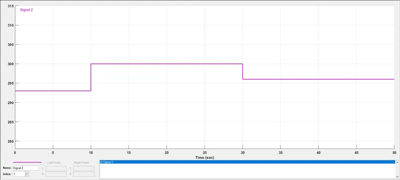
Input: An Input of Temperature source: 20 °C (293K) from 0 to 10 seconds, 27 °C (300K) from 10 to 30 seconds, 23 °C (296K) from 30 to 50 seconds is given
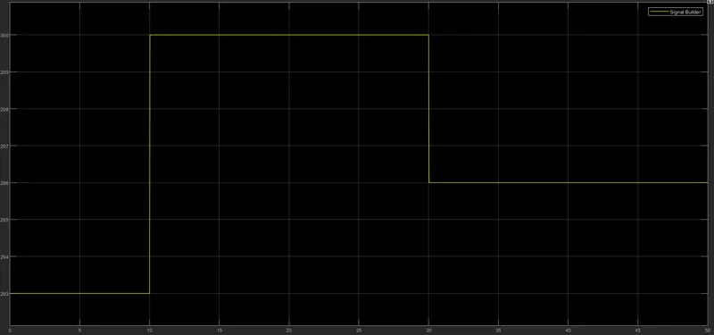
A plot for the voltage sensor
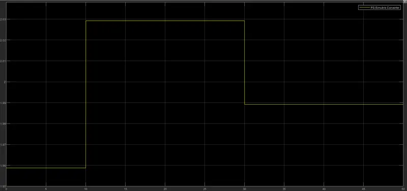
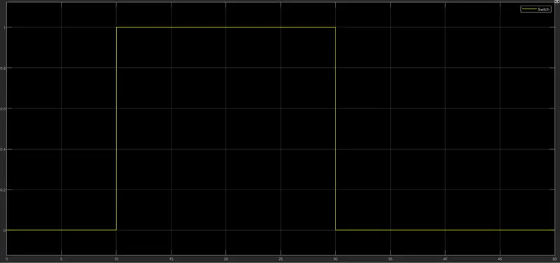
Output: For the first 10 sec and last 20 sec, the fan is OFF as the temperature is less than 25 °C and for 20-30 sec, the fan is ON as the temperature is greater than 25 °C.
Conclusion: The above given situations were successfully studied and simulated on Simulink.